The Design of an Intense Accelerator-Based
Epithermal Neutron Beam Prototype for BNCT
Using Near-Threshold Reactions
by
Charles L. Lee
Submitted to the Department of Nuclear Engineering
in partial fulfillment of the requirements for the degree of
Doctor of Philosophy in Nuclear Engineering
at the
MASSACHUSETTS INSTITUTE OF TECHNOLOGY
@ Massachusett
Author ...
August 1998
;s Instituteof Technology 1
'S
998. All rights reserved.
GScence
Department of Nuclear Engineering
August 7, 1998
Certified by.
Read by... ....
Xiao-Lin Zhou
Assistant Professor
Thesis Supervisor
...
Sow-Hsin Chen
Professor
Thesis Reader
/
i
Accepted by.
Sow-Hsin Chen
Chairman, Department Committee on Graduate Students
MASSACHUSETTS INSTITUTE OF TECHNOLOGY
JUL 20 1999
.... LIBRARIES
V ..-The Design of an Intense Accelerator-Based Epithermal
Neutron Beam Prototype for BNCT Using Near-Threshold
Reactions
by
Charles L. Lee
Submitted to the Department of Nuclear Engineering on August 7, 1998, in partial fulfillment of the
requirements for the degree of
Doctor of Philosophy in Nuclear Engineering
Abstract
Near-threshold boron neutron capture therapy (BNCT) uses proton energies only tens of keV above the (p,n) reaction threshold in lithium in order to reduce the
moderation requirements of the neutron source. The goals of this research were to prove the feasibility of this near-threshold concept for BNCT applications, using both calculation and experiment, and design a compact neutron source prototype from these results. This required a multidisciplinary development of methods for calculation of neutron yields, head phantom dosimetry, and accelerator target heat removal. First, a method was developed to accurately calculate thick target neutron yields for both near-threshold and higher energy proton beams, in lithium metal as well as lithium compounds. After these yields were experimentally verified, they were used as neutron sources for Monte Carlo (MCNP) simulations of neutron and photon transport in head phantoms. The theoretical and experimental determination of heat removal from a target backing with multiple fins, as well as numerical calculations of heat deposition profiles based on proton energy loss in target and backing materials, demonstrated that lithium integrity can be maintained for proton beam currents up to 2.5 mA. The final design uses a proton beam energy of 1.95 MeV and has a centerline epithermal neutron flux of 2.2 x 10⁸ n/cm2-sec/mA, an advantage depth of 5.7 cm, an advantage ratio of 4.3, and an advantage depth dose rate of 6.7 RBE-cGy/min/mA, corresponding to an irradiation time of 38 minutes with a 5 mA beam. Moderator, reflector, and shielding weigh substantially less than other accelerator BNCT designs based on higher proton energies, e.g. 2.5 MeV. The near-threshold concept is useful as a portable neutron source for hospital settings, with applications ranging from glioblastomas to melanomas and synovectomy.
Thesis Supervisor: Xiao-Lin Zhou Title: Assistant Professor
Acknowledgments
This thesis is the culmination of many years of hard work. However, this effort would not have been possible without the support of many important persons. I want to thank the following people for their help over the past eleven years:
My teacher and advisor, Xiao-Lin Zhou, has given guidance and support in helping me attain this degree. He has provided me with knowledge and experience that will be invaluable over the course of my professional career.
Professors Sow-Hsin Chen, Otto Harling, and Sidney Yip of MIT have given won-derful advice over the years, pertaining to my classes, thesis, and all scientific endeav-ors. Thank you for the benefit of your experience. In addition, Professor Jacquelyn Yanch has provided me with especially useful suggestions regarding my research. Her expertise in the field of accelerator BNCT is truly remarkable, and allowing me to attend her research group's weekly meetings provided excellent feedback on my own studies.
Emanuella Binello, Brandon Blackburn, Cynthia Chuang, David Gierga, Tim Goorley, Stead Kiger, Kent Riley, Haijun Song, and Susan White - the excellent group of doctoral candidates in the area of BNCT with whom I have worked over the last four years - have provided great intellectual support and friendship. I feel a special bond with all of these comrades-in-arms, the most impressive collection of students I've ever known.
Professor Frank Harmon of Idaho State University has been a terrific boss during my year working in Idaho, always making time if I needed to discuss anything. He has gone far above and beyond the call of duty in helping me over the past year. Dr. Yale Harker of the Idaho National Environmental and Engineering Laboratory (INEEL) has been my mentor in Idaho. He is a brilliant, creative, and supportive person who has really helped prepare me for the road ahead.
Dr. Rajat Kudchadker is a wonderful friend and a damn fine researcher, a truly giving person. Thanks especially for the room last summer and the curries that make my eyes water, even if you did start the whole "Larry" thing.
Roger Bartholomay, you beat me to finishing our degrees, but I guess I can let that slide. It is no exaggeration to say that my experiments would not have happened without your help. Wade Scates is an honest and positive person, always helping with and contributing to the many experiments of the past months. Good luck in your own degree, and remember, "Shake it baby, shake it!" Jim, Lane, and Brett of ISU have been incredibly helpful over the past year, making all the experiments work, even when I was certain they couldn't. You are a terrific group of guys, and I never could have finished this without your help.
Dawn May has been a wonderful friend and roommate in Idaho, a person whose laugh is one of the nicest things I can think of - I always want to join in. You are so loving and supportive, I'll never forget it. Extra thanks to Shep, Pepito, and Spaz.
Doug Denison has been my great friend and roommate in Boston. You are an intellectual powerhouse with a killer wit that is all the more wonderful because of its subtlety. Always remember, "No moleste el gato spectacularrrrr."
Heather Blasdell is my soul mate and the most exciting person I know. Heather is cool beyond words, and I certainly wouldn't be where I am now without her help. Anne Moulton, my "honey-fritter", will always have a very special place in my heart. Besides a being a wonderful friend, her strength and love were instrumental in helping me recognize and value my gifts.
Mike Jeffery, randomly assigned as my roommate freshman year of college, is truly one of my friends for life. He is honorable and caring, and I really miss being able to spend time together like we used to. You know, if Tom Hanks and Data had a son...
Dana Nelson, my movie partner for so many Fridays over the years, has a smile that is unforgettable. She is a superb friend and confidante.
Mom and Dad, you have been unfaltering in your love and support of me, and I thank you for it all. You are the reason behind everything I've been able to achieve. Last but certainly not least, my sisters, Heather and Anna, are amazing. Spending time with you becomes a greater joy with every passing year. You have unlimited potential, and I have great faith in what your lives have in store.
Contents
1 Introduction 19
1.1 An Overview of BNCT ... ... 19
1.2 Neutron Beam Requirements for BNCT . ... 21
1.2.1 Neutron Energy Requirements . ... 21
1.2.2 Beam Contamination Components . ... 21
1.2.3 RBE Effects ... 23
1.3 Accelerator-Based BNCT ... 24
1.4 Research Goals and Thesis Summary . ... 27
2 Thick Target Neutron Yields
2.1 T heory . . . . 2.1.1 Near-Threshold Kinematics . . . . 2.1.2 Near-Threshold (p,n) Cross Sections . . . . 2.2 Calculated and Experimental Results . . . . 2.2.1 Thick Target Neutron Yield Surface . . . . 2.2.2 Thick Target Energy Spectra and Angular Distributions 2.2.3 Thick Target Total Neutron Yields . . . . 2.2.4 Application to Lithium Compounds . . . . 2.2.5 Partially Thick Targets ...
2.2.6 Model of Lithium Metal Oxidation in Air . . . .
29 30 30 35 38 38 40 44 46 48 55
3 Feasibility of Near-Threshold BNCT
3.1 What is necessary for a useful BNCT treatment beam? ... 3.2 Light Water versus Heavy Water ...
3.3 Demonstration of Feasibility . ...
4 Near-Threshold BNCT Dosimetry
4.1 BNCT Treatment Parameters . . . . 4.2 MCNP Design .. . . . . . ..
4.3 Photons Produced in the Lithium Target 4.4 Dose Calculations . . . ..
4.4.1 Moderator Considerations . . . . 4.4.2 Target Backing Considerations . 4.4.3 Thermal Neutron Attenuation . 4.4.4 Photon Attenuation . . . . 4.5 Choice of Beam ... ....
5 Near-Threshold BNCT Target Heat Removal
5.1 Multi-Fin Target Heat Removal . . . . ... 5.1.1 Single Fin Theory ... . . . . ...
5.1.2 Extension to Multiple Fins . . . . . . . .... 5.1.3 Low Power Heat Removal Experiments . . . . 5.1.4 High Power Heat Removal Experiments . . . . 5.1.5 Critical Heat Flux (CHF) Concerns . . . . 5.2 Heat Deposition Profiles of Proton Beams . . . .
5.2.1 Steady State Temperature Drops . . . ... 5.2.2 Transient Temperature Behavior (Beam Pulsing)
6 Final Target Design
65 .. . . . . . 65 . . . . . . . . 69 . . . . . . . . . . 72 .. . . . . . . 78 . . . . . 79 . . . . . . . . . . . . 86 . . . . . . . . 92 . . . . . . . 94 . . ... . 98 101 . . 102 . . 103 . . 105 112 117 122 123 124 . . 133 137
7 Summary and Future Work
7.1 Sum m ary . . . .
7.2 Suggestions for Future Work ...
A Thick Target Neutron Yield Program (li.f)
B Tabulated (p,n) Cross Section Coefficients (sigmafile)
C Tabulated Spline Coefficients (sigmaspline)
D Example MCNP Input
E Multi-Fin Specific Temperature Rise Calculation (flow. f)
F Heat Deposition Computational Method
G Design of a Head Phantom for BNCT Beam Verification
H Publications and Presentations
149 149 151 155 177 179 181 193 199 203 207
List of Figures
1-1 Total (p,n) Cross Section for 7Li. From [1]. The lower dashed curve is the cross section for the reaction leading to the ground state of 7Be,
while the solid curve is the cross section for reactions leading to both the ground and first excited states of 7Be. . ... 25 2-1 Proton Energy Contours for Thick Lithium Targets. ... . 31 2-2 Differential Neutron Yield for 1.95 MeV Protons Incident on Natural
Lithium M etal. ... ... .. 38 2-3 A Comparison of 0 Thick Target Neutron Yields ... . . . 39 2-4 Near-Threshold Thick Target Neutron Energy Spectra for Natural
Lithium Metal ... ... 41 2-5 Near-Threshold Thick Target Neutron Angular Distributions for
Nat-ural Lithium M etal ... 42 2-6 Near-Threshold Thick Target Neutron Angular Yields for Natural Lithium
Metal. These yields, with units of neutrons/degree mC, are obtained by multiplication of the angular distributions of Figure 2-5 by the solid angle differential element. ... 43 2-7 Calculated and Experimental Total Neutron Yields for Thick Lithium
M etal Targets .. . . . .. . . . .. . 45 2-8 Schematic of Long Counter Used to Measure Total Neutron Yields for
2-9 Calculated and Experimental Total Neutron Yields for Thick LiF Targets 49 2-10 Calculated and Experimental Total Neutron Yields for Thick Li20
Tar-gets ... ... ... 50
2-11 Contours Defining Neutron Production in a Partially Thick Target. Neutrons are only produced with energy and angle combinations be-tween the upper and lower contours. . ... 52
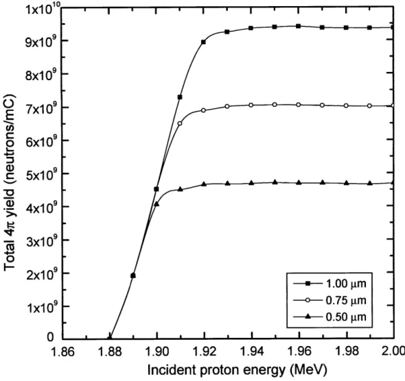
2-12 Calculated Total Neutron Yields for Partially Thick LiF Targets . . . 53
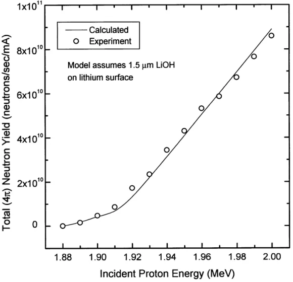
2-13 Calculated and Experimental Total Neutron Yields for a 1 pm Target 54 2-14 Calculated and Experimental Total Neutron yields for a Thick Lithium Target Exposed to Air. A 1.5 /pm LiOH target thickness is assumed. . 57 3-1 Neutron Energy Spectra as a Function of H20 Moderator Thickness for 1.91 MeV Protons ... 62
4-1 BNCT Treatment Parameter Definition . ... 67
4-2 MCNP geometry ... ... ... ... 69
4-3 Total cross section for (p,-) reaction in 7Li . ... 73
4-4 Experimental 478 keV Gamma Yield for Inelastic Proton Scattering in Lithium. Experimental points are taken from Ref. [3]. The least squares quadratic fit to the data is given in Eq. 4.3 . ... 74
4-5 Effect of 7Li(p,p'y)7Li Photons on BNCT Treatment Parameters . . . 76
4-6 Variation of RBE-AD with Moderator Thickness for Near-Threshold Beams ... ... ... 79
4-7 Variation of RBE-ADDR with Moderator Thickness for Near-Threshold Beams ... ... ... ... 80
4-8 Percentages of Healthy Tissue RBE Dose Components on Front Phan-tom Face for 1.95 MeV Proton Beams. . ... . 82
4-9 Comparison of RBE Advantage Depth and RBE Advantage Ratio for 1.95 MeV Proton Beams ... 83 4-10 Variation of RBE-AD and RBE-ADDR as a Function of Proton Beam
Energy and Moderator Thickness. The vertical dotted line indicates the minimum acceptable RBE-AD of 5 cm. The upper and lower hor-izontal dotted lines correspond to total healthy tissue RBE doses of 2000 cGy and 1250 cGy, respectively. Points in the upper quadrant satisfy the requirements for a BNCT neutron beam. ... . 85 4-11 Effect of Target Backing Materials on RBE Advantage Depth for 1.95 MeV
Protons . . . .. . . . . . 87 4-12 Experimental 0O Photon Yields from Cu, Al, and Stainless Steel (Type
304) Backing Materials for 1.95 MeV Protons. Photons were detected using a 5" x 5" NaI crystal. ... 90 4-13 Effect of Gammas from Inelastic Proton Scattering in Aluminum on
RBE Advantage Depth for 1.95 MeV Protons ... 91 4-14 Effects of Cd and 6Li thermal neutron shields on RBE-AD for 1.95 MeV
Protons . . . .... . . . .. . . . . 93 4-15 Variation of RBE-AD and RBE-ADDR with Moderator Thickness for
1.95 MeV Protons with and without Thermal Neutron Absorber Ma-terials. The vertical dotted line indicates the minimum acceptable RBE-AD of 5 cm. The upper and lower horizontal dotted lines corre-spond to total healthy tissue RBE doses of 2000 cGy and 1250 cGy, respectively. Points in the upper quadrant satisfy the requirements for a BNCT neutron beam ... 95 4-16 Effect of Lead Shielding on the Maximum RBE Advantage Depth for
1.95 M eV Protons ... 96
4-17 Variation of RBE-ADDR on Pb Thickness for 1.95 MeV Protons .. . 97
4-18 Effect of 6Li and Pb on BNCT Treatment Parameters for 1.95 MeV
Protons. The vertical dotted line indicates the minimum acceptable RBE-AD of 5 cm. The upper and lower horizontal dotted lines corre-spond to total healthy tissue RBE doses of 2000 cGy and 1250 cGy, respectively. Points in the upper quadrant satisfy the requirements for a BNCT neutron beam. ... ... ... 99
5-1 Definition of Fin Parameters. From [4]. . ... 104 5-2 Multi-Fin Target Design . ... ... 106 5-3 Calculated Temperature Drop per Unit Heat Input Across Fins for a
Multi-Fin Target Design ... ... 111 5-4 Schematic of Low Power Heat Removal Experimental Setup for a
Multi-Fin Target Design ... . ... 113 5-5 Experimental Variation of Heat Input versus Thermistor Temperature
Difference for a Multi-Fin Target Design. The coolant flow rate is 8 gallons per minute ... .. ... .. ... .. 115 5-6 Comparison of Experimental and Calculated Multi-Fin Temperature
Drops Across Low Power Experimental Setup . ... 118 5-7 Target Regions and Associated Temperature Drops . ... 125 5-8 Temperature Profile for 1.95 MeV Protons Stopping in Lithium and
Copper. The lithium thickness is 9.43 pm, just enough to pass the
(p,n) threshold at the lithium-copper boundary. The dotted line shows
the incorrect temperature variation based on the assumption of all heat incident from the left ... ... 128 5-9 Temperature Drop Across Stopping Region as a Function of Incident
Proton Beam Energy. In all cases, the proton energy at the lithium/copper boundary was the (p,n) reaction threshold of 1.88 MeV... . 129
5-10 Temperature Drop Across Stopping Region as a Function of Lithium Target Thickness ... 130 5-11 Maximum Deviation of Target Temperature from Average vs. Duty
Factor for Several Repetition Rates. From [5]. . ... 134 6-1 Moderator Design for Final CTU Design. Stainless steel surrounding
the moderator unit is not shown, and the figure is not to scale. .... 138 6-2 Final CTU Design ... 141 6-3 RBE-AD and RBE-AR for Final Near-Threshold BNCT Neutron Source
Design for Various Moderator Thicknesses. The proton energy is 1.95 MeV. 142 6-4 RBE-AD vs. RBE-ADDR for Final Near-Threshold BNCT Neutron
Source Design for Various Moderator Thicknesses. The proton energy is 1.95 MeV. The vertical dotted line indicates the minimum acceptable RBE-AD of 5 cm. The upper and lower horizontal dotted lines corre-spond to total healthy tissue RBE doses of 2000 cGy and 1250 cGy, respectively. Points in the upper quadrant satisfy the requirements for a BNCT neutron beam. ... 143 6-5 Dose Depth Profiles along Phantom Centerline for 3 cm H20
Modera-tor. The proton energy is 1.95 MeV. . ... 144 6-6 Radial Variation of the Epithermal Neutron Flux Exiting the
Moder-ator. The proton energy is 1.95 MeV. . ... 145 6-7 Radial Variation of Advantage Region for a 3 cm Light Water
Moder-ator. Each point indicates the depth at a given radial distance from the centerline where the tumor dose rate equals the maximum healthy tissue dose rate. The proton energy is 1.95 MeV. . ... 147
List of Tables
2.1 Near-Threshold Thick Target Neutron Yields for Natural Lithium Metal 44 2.2 Near-Threshold Thick Target Neutron Yields for Lithium Compounds.
Yields are in units of neutrons/mC. . ... 51
3.1 Existing Epithermal Neutron Beams for BNCT Clinical Trials in the U .S. and Europe .. . .. . . .. . .... . .. . .. . .. . .. . .. 60 3.2 Calculated Neutron Beam Parameters as a Function of Moderator
Thickness for 1.91 and 1.95 MeV Protons . ... 63
4.1 RBE Values for BNCT Calculations . ... 68 4.2 Brain Material Specification for the MCNP Phantom . ... 71 4.3 Comparison of Neutron and Photon Yields for Thick Lithium Targets 75 4.4 Q-Values for (p,n) Reactions in Target Backing Material Candidates 88 4.5 Total Gamma Yields from Inelastic Proton Scattering in Aluminum
for 1.88 M eV Protons ... 90 4.6 Physical Properties of Target Backing Material Candidates ... 92
5.1 Geometrical Factors for Multi-Fin Target Flow Rate Calculations . . 108 5.2 Experimental Temperature Drops between Coolant and Copper Rod
Therm istors . . . . . 116 5.3 High Power Experimental Temperature Rises between Coolant and
Copper Rod Surface ... 121
5.4 Comparison of Low and High Power Experimental Temperature Rises Across Fins ... . . ... ... 122 5.5 Temperature Drops for Near-Threshold and Higher Proton Energies . 132 6.1 Free Beam Parameters for Final Design of Near-Threshold BNCT
Neu-tron Source ... ... ... 142 G.1 Physical Properties of Body Parts and Phantom . ... 204
Chapter 1
Introduction
1.1
An Overview of BNCT
Extensive research has been undertaken in the past 50 years in the United States, Europe, and Japan in the area of boron neutron capture therapy (BNCT), a novel method for treating certain malignant brain cancers, such as glioblastoma multiforme (GBM). The GBM mass in the brain generally has a large central mass (the primary tumor mass) plus extensive, root-like fingerlets that invade the surrounding healthy tissue. GBM cells tend to be quite resistant to traditional (photon) radiation treat-ment, and the tumor fingerlets make surgical debulking ineffective since some of the fingerlets almost always remain. These tumors are also not generally diagnosed until they are quite large and able to affect normal brain function, and by this time, the expected patient survival time is short (often less than six months). In the United States alone, more than 11,000 people were diagnosed with GBMs in 1995, so there is a need and a market for an effective treatment of this tumor [6].
The BNCT treatment is a binary modality that consists of preferentially load-ing a compound containload-ing 10B into the tumor location, followed by the irradiation of the patient with a beam of neutrons. Damage to cancer cells comes from the
densely ionizing, high linear energy transfer (LET) heavy charged particles from the
10B(n,a)'Li reaction, whose cross section follows a 1/v law and hence is dominant
for thermal neutrons. Since the range of the reaction products is on the order of cell dimensions, the heaviest tissue damage is restricted to the tumor cells, provided the boron compound has a substantially higher concentration in tumor compared with the surrounding healthy tissue. The BNCT treatment modality is considered binary because two events must occur for high dose rates to tissue: introduction of 10B and
irradiation by thermal neutrons.
While BNCT in Japan has historically removed the skull cap during the treatment so that a thermal neutron beam can be used [7], the more common methodology in current practice and theory removes the skull cap during a surgical debulking of the primary tumor mass but replaces the cap during the irradiation [6]. Surgical debulk-ing is generally necessary because by the time the tumor is diagnosed, the primary mass is large and has developed its own vasculature. Irradiation of this primary mass can destroy this system of blood vessels, causing internal bleeding in the brain. The replacement of the skull cap reduces chances for infection and allows somewhat less strenuous requirements on treatment room sterility. Since thermal neutrons do not have sufficient penetrability to reach deep seated tumors, an epithermal beam of neu-trons is necessary in order for the skull cap to remain intact during patient treatment. (High energy neutrons are less desirable for reasons described in Section 1.2 below.) The epithermal neutrons slow down within the patient, reaching thermal energies in the tumor region.
Excellent summaries of many different aspects of BNCT are found in the May 1997 issue of Journal of Neuro-Oncology, including reviews of the rationale of BNCT [6], history [7], neutron beam requirements [8], boron compounds [9], and microdosimetry [10]. The 1996 review in Cancer Investigation is also excellent [11]. Finally, the bi-annually proceedings of the International Symposium on Neutron Cancer Therapy for
Cancer provide a centralized source for the latest developments in all areas of neutron capture therapy research.
1.2
Neutron Beam Requirements for BNCT
1.2.1
Neutron Energy Requirements
The neutron source requirements peculiar to the BNCT methodology are complex and difficult to achieve in practice. It is worth discussing each major requirement in detail, since these beam parameters will be crucial to the development of the neutron beams in this research.
As mentioned previously, BNCT beams utilize epithermal neutrons for patient treatment. The first question that comes to mind is: what energy range is considered epithermal for this application? Many authors have tackled this question, and the general consensus at the time of writing is from several electron-volts (eV) to several tens of keV [8, 12]. The criteria for determining this range basically rest on balancing the need for high penetrability and low dose to healthy tissue. High penetrability through the skull and outer brain allows the treatment of tumors located deep in the patient's head, obviously necessary for any practical radiation treatment modality. Low dose to healthy tissue is one of the biggest selling points of BNCT: there is the potential for selective damage to tumor relative to healthy tissue, so any components of the treatment beam that reduce this therapeutic advantage are undesirable.
1.2.2
Beam Contamination Components
Radiation dose to the patient in BNCT consists of three main components: neutron dose, which is often subdivided into fast, epithermal, and thermal doses; gamma dose; and dose due to the high LET heavy charged particles from the fission of 10B, generally called the 10B dose. Some amount of dose due to neutrons is inevitable, but fast and
thermal components of the beam striking the patient are undesirable for different reasons. Fast neutrons deposit dose primarily near the skin surface and skull, since these neutrons quickly slow down into the epithermal region. The primary drawback of the fast neutron component is the steady increase of KERMA values with neutron energy in the fast region-the principle neutron interaction for fast neutrons in tissue is proton recoils produced by elastic scattering with hydrogen, and increasing neutron energy leads to larger proton kinetic energies, and hence larger tissue doses-which deposits large, shallow doses that do nothing to aid the treatment of the deep-seated tumors in question.
Thermal neutrons deposit energy in tissue primarily from the 14N( n,p)14C reaction,
which produces a 580 keV proton and a 40 keV recoiling 14C nucleus [13]. In addition,
thermal neutrons are unable to penetrate the skull, so they too are unable to aid in the BNCT process. Note, however, that while fast neutrons produce large doses at shallow depths, they can still slow down in tissue to thermal energies and be captured by 10B in the tumor, so it is an oversimplification to consider them useless.
The dose from gamma contamination of the beam is indiscriminate: it affects both tumor and healthy tissue to the same degree, reducing the effectiveness of the treat-ment. Gamma contamination will always be present in a neutron beam, but careful beam design can reduce this component to acceptable levels (see Chapter 4). Gamma contamination is primarily produced from the radiative capture of thermal neutrons by hydrogen in the patient via the 1H(n,y)2H reaction, which may be viewed as an
irreducible gamma background that must be included in all patient treatment plan-ning. Gamma contamination can also be produced from interactions in an accelerator target; target backing material; or moderator, filter, and reflector materials.
The final dose component, the 10B dose, should be very high in the tumor and very low in healthy tissue. The only real control over this component is in the phar-macological aspects of the compound used to transport the boron to the tumor site.
A high tumor-to-healthy tissue uptake ratio, as well as high tumor uptake levels, are necessary for the success of a BNCT treatment. Sufficiently high uptake ratios and tumor uptake levels can swamp the relative contribution of the contamination doses, reduce treatment times, and improve the experience for the patient by reducing side effects like erythema and epilation. Since the control over this component lies in the hands of chemists and pharmacologists, it is effectively constant for this research, although the degree of beam thermalization will correlate with the 10B dose. The specific tumor-to-healthy tissue uptake ratio and 10B concentration in tumor used in this research are given in Section 3.1.
1.2.3
RBE Effects
Whenever radiation dose is applied to a biological organism, the concept of relative biological effectiveness (RBE) must be applied to dose calculations. The RBE concept is necessary since equal physical doses (energy absorption per unit mass) for different types of ionizing radiation do not produce identical biological effects. In general, higher LET radiations such as neutrons and heavy charged particles are more effective in producing damage in an organism, i.e. have higher RBE values, than lower LET particles such as electrons, positrons, and photons [14]. The definition of RBE for a particle i is generally taken to be the ratio Dx/Di, where Dx and Di are the doses of 250 kVp X rays and particle i, respectively, needed to produce a given biological endpoint [15]. It is important to note that RBE depends on many factors, including the biological endpoint of interest, the energies of the radiations considered, and in the case of 10B dose, the microscopic distribution of 10B in tumor and healthy tissue cells
[16, 17, 18]. The exact RBE values for the dose components in BNCT are unknown,
but reasonable estimates are necessary for adequate dosimetry and neutron beam design so that the relative contribution of good and bad components is accurately gauged. The exact RBE values used in this research will be discussed in Chapter 4.
1.3
Accelerator-Based BNCT
While only certain nuclear research reactors are currently performing clinical BNCT trials in the United States and Europe [19, 20], widespread future applicability of this treatment modality will likely require the use of charged particle accelerators that can be used in a clinical environment. The application of particle accelerators for this problem is not a trivial task. In order to allow for reasonable patient treatment times, accelerator currents will need to be on the order of milliamps [21, 22, 23, 24]. These high currents are not only difficult to obtain for heavy charged particles such as protons and deuterons; such high currents will also deposit kilowatts of heat as the charged particles lose energy in the target, making target cooling difficult. Finally, the particular requirements on the neutron beam for BNCT (discussed in the previous section), as well as the need for large neutron production rates, will dictate the choice(s) for the charged particle- induced reactions to be used. The specific aspects of the 7Li(p,n)'Be reaction that is considered in this research meet these criteria.
The 7Li(p,n)'Be reaction cross section is shown in Figure 1-1. The total cross sections for the reaction leading to the ground state of 7Be, as well as the combination
of ground and first excited 7Be states, are given. The cross section is seen to rise
rapidly from a threshold at 1.88 MeV to a plateau of about 269 mb from 1.93 MeV to 2.00 MeV. This plateau is followed by a large resonance centered at 2.25 MeV with a peak cross section of nearly 590 mb. This large cross section, combined with a low threshold energy, makes the 7Li(p,n)7Be reaction an excellent source of relatively low energy neutrons.
One may ask, why not use any nuclear reaction with high neutron yields for accel-erator BNCT? For example, the D-D and D-T reactions are well studied and produce about 109 and 1011 neutrons/sec/mA, respectively, at easily obtained deuteron ener-gies of 100-300 keV [25]. Deuterated materials are easier to handle than pure lithium metal, which has a low melting point (1810C) and readily oxidizes in air and water
600 I I I I I I I - 7Li(p,n)7Be + 7Li(p,n)7Be 500 - - - Li(p,n)7Be only E 400 o U) 300 -O S200 0 F-100 1.5 2.0 2.5 3.0 3.5 4.0 4.5 5.0
Lab Proton Energy (MeV)
Figure 1-1: Total (p,n) Cross Section for 7Li. From [1]. The lower dashed curve is the cross section for the reaction leading to the ground state of 7Be, while the solid curve is the cross section for reactions leading to both the ground and first excited states of 7Be.
[26]. So why use a (p,n) reaction, especially 7Li(p,n)7Be?
The answer lies in the requirements for BNCT that were spelled out in Section 1.2, namely that useful neutron energies for BNCT are in the range of about 1 eV to 10 keV. The D-D and D-T reactions produce neutrons with energies of almost 3 MeV and 14 MeV, respectively, due to the positive Q-values of the reactions. These neutron energies are much too high for patient treatment [27], and hence need extensive (greater than 20 cm of D20) moderation to bring the average energy down to the
useful range for BNCT. The concomitant attenuation of the neutron flux makes the current requirement very high if patient treatment times are to be reasonable, and even so, the fast neutron component of these sources can be reasonably high, especially when the high RBE values for fast neutrons are considered. By comparison, the maximum energy of neutrons from the bombardment of 2.5 MeV protons on a thick lithium target is 787 keV, the average neutron energy is 326 keV, and the neutron yield is 8.9 x 10¹¹ neutrons/sec/mA.
One of the most striking features of Figure 1-1 is the extremely rapid rise of the cross section immediately after threshold. Specifically, the cross section reaches the plateau value of 269 mb within 50 keV of the reaction threshold. This fact, combined with the neutron beam requirements described in Sectionl.2, has led us to consider near-threshold reactions in lithium targets [28, 29, 30, 31, 32, 33, 34, 35]. Near-threshold BNCT uses an accelerator proton beam energy several tens of keV above the 7Li(p,n)7Be reaction threshold to produce neutrons for BNCT treatments. Working close to threshold reduces the thick target yield compared to higher beam energies such as 2.5 MeV, but the maximum and mean neutron energies are much lower, requiring less moderation and hence less attenuation of the raw neutron yield from the target. For comparison with the neutron yield and energies for 2.5 MeV protons described above, the maximum energy of neutrons from the bombardment of 1.91 MeV protons is 105.3 keV and the average neutron energy is only 42.4 keV,
while the neutron yield is 2.4 x 10¹⁰ neutrons/sec/mA, a substantial yield considering the lowered moderation requirements for this neutron source.
1.4
Research Goals and Thesis Summary
A study of the viability of near-threshold neutron beams as a neutron source for BNCT brain treatments requires a multidisciplinary analysis of the total engineering of the neutron beam source. Primary requirements include the development of a method for calculating near-threshold neutron yields, Monte Carlo simulation of head phantom dosimetry, and accelerator target heat removal.
First, a method was designed and implemented to accurately calculate thick tar-get neutron yields for near-threshold proton beams that can be applied in a
self-consistent manner to higher energy proton beams, in lithium metal as well as lithium compounds. After these yields were experimentally verified, they were used as sources for Monte Carlo (MCNP) simulations of neutron and photon transport in head phan-toms in order to determine the effect of proton beam energy, moderator thickness, gamma production in the target, backing materials, and thermal neutron and gamma shielding on beam parameters such as penetration depth and treatment time. The engineering design of the neutron source involved theoretical and experimental deter-mination of heat removal capabilities for a multi-fin target backing design, as well as numerical calculation of the heat deposition profiles for protons stopping in lithium and backing materials. The results of these studies were combined into a unified neutron source design, including the design of an acrylic head phantom for measuring the primary dose components of the final beam.
Chapter 2
Thick Target Neutron Yields
In the investigation of near-threshold BNCT, it is necessary to have an accurate method for computing thick target neutron yields. In particular, both the energy spectrum and angular distribution of the neutrons produced by protons of a certain bombarding energy are required. It has been determined that the existing data for computing thick target yields is insufficient for accurate yield calculation over the range of incident proton energies of interest in this research. In particular, tabu-lated cross sections provide excellent data for energies above about 1.95 MeV, but mathematical peculiarities close to the reaction threshold lead to erroneous results in this region. Analytical forms of the differential cross section work well close to threshold, but are incorrect for higher energies. A self-consistent method was de-veloped for producing differential thick target neutron yields for all proton energies below 2.50 MeV. This method has also been modified to determine neutron yields from compounds that contain lithium, as well as extending the method to partially thick targets. Partially thick targets are of sufficient thickness to result in significant
proton energy loss, but are not sufficiently thick to slow the proton energy below the reaction threshold. Finally, a model of the effect of the oxidation layer formed when lithium metal is exposed to air is presented.
This chapter describes the method developed to generate the thick target dif-ferential neutron yields from near-threshold protons, focusing on the mathematical difficulties that arise for calculations within several keV of the reaction threshold and the techniques for overcoming these complexities. The results of calculations using this method are presented, including differential and total yields for thick targets, partially thick targets, and targets exposed to air. Comparisons of calculated results with experimental measurements are included.
2.1
Theory
2.1.1
Near-Threshold Kinematics
For illustrative purposes, consider a monoenergetic incident proton beam energy, Epo,
of 1.95 MeV striking a thick lithium target. A thick target is defined to be of sufficient thickness to slow protons down to energies below the reaction threshold. Figure 2-1 provides kinematic relations between 0, the polar angle of emission of the neutron in the laboratory (LAB) frame of reference; En, the LAB neutron energy; and Ep, the LAB proton energy that produced the neutron, for the 7Li(p,n)'Be reaction. Lines
of constant Ep are plotted from Epo to Ep = Eth, the threshold energy of 1.88 MeV. When the proton beam impinges on a thick lithium target, the initial neutron yield will follow the energy and angle behavior shown on the uppermost contour. As the protons lose energy in the target, the energy and angular dependence of the neutron yield will be determined from contours of continuously decreasing proton energy, until neutrons are only produced in the forward direction at an energy of 29.7 keV at Eth. The neutron energy at threshold is determined from En(Eth) = mpmnEth/(mBe + mn)2, where mp, mn, and mBe are the proton, neutron, and 7Be nuclear masses, respectively. A thick lithium target will only produce neutrons with energies and angles corresponding to proton energies below Epo, i.e. neutrons will
180 1.95 MeV 160
1.9
140 -1.9 12 1.92 S120 ) 1.91 (D 100 W C- 1.90 O 80 a) 1.89 Z 60 40-Ithreshold 20-0 20 40 60 80 100 120 140 160 180Lab Neutron Emission Angle (degrees)
not be produced with energies and angles above the uppermost contour of Figure 2-1. Note that for proton energies below
E* P - B(Be + mn - mP) Eth = 1.92 MeV, (2.1)
mBe(mBe + mn - mp) - mpmn
neutron production is double-valued, giving two neutron energies for each LAB angle of emission. In addition, neutrons are only produced in the forward direction (0 <
900).
It is clear from Figure 2-1 that any combination of 0 and En uniquely specifies Ep, and the differential neutron yield is therefore a pointwise function of these variables. This observation means that it is not necessary to discretize the proton energy as the beam slows down in the target. The differential neutron yield at each proton energy is given by dorp, dQ' dEp d2Y dQ' dQ dE, d2 (0, En) =NLi-7 d d (2.2) dQ dE, -dEp dx
where d2Y/dQ dEn is the differential neutron yield in units of neutrons per keV per
steradian per millicoulomb, NLi-7 is the 7Li (target) atomic density, dapn/dQ' is the center-of-mass (CM) differential (p,n) cross section, dQ and dQ' are differential solid angles in the LAB and CM, respectively, and -dEp/dx is the proton stopping power in the target.
In order to have more compact notation in the equations that follow, it is useful to introduce two kinematic parameters, y and ( [36]. 7 is defined as the ratio of
the post-reaction speed of the CM to the speed of the neutron in the CM. The following expression for y can be obtained from the nonrelativistic conservation of linear momentum and energy equations:
S Be(Bmn Ep
Note that as Ep approaches threshold, y -+ oo, and for Ep < E , 7 > 1. In addition, the parameter ( is defined by
(2 = 1/y2 - sin2 8. (2.4)
The first step in the determination of the thick target differential neutron yield is choosing a set of (0,E,) grid points at which d2Y/dQ dE, is calculated. This research
used 1', 1-keV intervals ranging from 0O to 1800 and 0 to 250 keV. It is important to note that a different grid spacing will lead to a different number of calculated
yields, but the yield computed at a particular location is independent of mesh size and hence will not change. For each grid point, the proton energy Ep is calculated in a manner similar to that used to produce the contours of Figure 2-1. Once E, has
been determined, 7, (, and the mass stopping power are immediately calculated since
these quantities are functions of E, alone. The mass stopping power is determined from analytic formulas fit to experimental data [37].
Since the differential cross section dop,,/dQ' is a function of the CM angle of emission, 0', the next step in the calculation is to determine the correct value of 8'
corresponding to (0,E,). For Ep > EP, neutron production is single-valued and
0' = 0 + sin-'(7 sin 0), (2.5)
while for Ep < E, neutron production is double-valued and there are two possibilities for 8'. These CM angles, 0' and 0', are related to 0 by
0~ = 0 + sin-l(y sin 0) (2.6)
0 = r + 0 - sin-l(y sin 0). (2.7)
higher neutron energies, while 0' is directed in the backward direction and corresponds to lower neutron energies. Now define a neutron energy Eequal:
Eequal = (1 + 72)E', (2.8) where E" is the CM neutron energy, given by
E mBe(mBe + m - m)P
En =2 (E, - Eth). (2.9)
(mBe + mn)2
It is straightforward to demonstrate that for a given proton energy Ep, Eequal cor-responds to the point where 0' = 0' = 0 + 90'. From the statements above, if
En > Eequal for the grid point in question, we will need 0' and Eq. (2.6) must be
calculated; if E, < Eequa, 0' is the correct CM angle and Eq. (2.7) must be used. Note from Eq. (2.6) that the maximum angle of emission for proton energies below E* is given by Omax = sin-l(1/7).
It now remains to determine the CM differential cross section and the Jacobian
transformations given in Eq. (2.2). These transformations are given by
'= ± (cos 0 ± )2 (2.10)
dQ
dE 1 [ (mnBe + mn)2E] (2.11)
dEn cos 0 + mpmnEp~(cos 0 ± ) ± mBe(mBe + mn - mp)Eth
In Eqs. (2.10) and (2.11), the + sign is used when 0' = 0' and the - sign is used when
0' = 0'. Care must be taken in employing these expressions in various regions of (0,E")
space. For example, in the neighborhood of Omax, dQ'/d - oo and dEp/dEn -+ 0. This means that Eq. (2.2) is indeterminate at points where 0 = Omax, and this
will create a computational problem for (0,En) values at or close to these points. However, this problem can be easily remedied by considering the product of dQ'/dQ
and dEp/dE,, given by
da' dEp, (mBe + m,) 2(cos 0 f )yEP
(2.12)
dQ dE, - mpmnE (cos 0 ± () ± mBe(mBe + m, - mp)Eth
Now the limit for this product of Jacobians is given by
dQ' dEp (mBe + mn)2Ep
lir = k/7 2 - 1 (2.13)
o-+omaz dQ dEn mBe(mBe + mn - mp)Eth
Using the product of the Jacobian transformations therefore circumvents the com-putational problems that arise when calculating each transformation separately. For this reason, and since the expression for the Jacobian product has the simple closed form given in Eq. (2.12), this expression is used in all differential yield calculations.
All calculational difficulties are not removed by the substitution given in Eq. (2.12). The greatest difficulty in near-threshold neutron yield calculations comes from the behavior of y as E, -+ Eth: as pointed out earlier, y becomes unbounded, and dQ'/dQ dEp/dEn -+ oc. We know that the CM differential cross section must go to zero at the reaction threshold, so Eq. (2.2) is still indeterminate (0 - oc) at
E, = Eth. To understand how this problem is overcome, the particular aspects of the
7Li(p,n)7Be cross section near threshold must be considered.
2.1.2
Near-Threshold
(p,n)
Cross Sections
In 1975, Liskien and Paulsen compiled extensive experimental cross section measure-ments from the existing literature and generated best fits to the data over the proton energy range from 1.95 MeV to 7 MeV for both the reaction leading to the ground state of 7Be and the first excited state, which has a threshold at 2.37 MeV [1]. These
CM cross sections are given as Legendre polynomial expansions:
dapn 1 dopn 3
d (') = - (0) Ai(Ep) P(cos '). (2.14)
i=0
The proton energy-dependent parameters Ao, A1, A2, A3, and do-pn/dQ'(0) are
tab-ulated, making it extremely simple to use their fits for calculating reaction cross sections. In order to replicate the smooth variation of the cross section parameters with proton energy, cubic splines were fit through the data points given in Liskien and Paulsen's paper.
The Liskien and Paulsen tabulated cross section data are good for energies above 1.95 MeV, but they don't help to resolve the problem of indeterminacy near the reaction threshold. It is necessary to use an analytical form for the CM differential cross section to determine the actual near-threshold limits of the terms in Eq. (2.2). It has been pointed out by Newson et al., as well as other sources [38, 39, 36, 40, 41, 42], that the reaction cross section has the form expected from a broad s-wave resonance centered at about 1.93 MeV. The resulting form of the theoretical cross section is
drpn= A (2.15)
dn' EP (1 + X)2
where x = Fn/F, the ratio of the neutron to proton channel widths, which has a functional form on the narrow energy range near threshold of x = Co 1 - Eth/E,
and Co and A are constants to be determined. A value of Co = 6 is consistent with the cross section data of Newson et al.. A proton energy of 1.925 MeV was chosen as the boundary between tabulated and theoretical cross section values. This energy is roughly the upper limit of applicability of Eq. (2.15) (-50 keV above threshold), and the theoretical expression for dgpn/dQ' has zero slope at this energy, making a smooth transition to the interpolated values a simple matter. Theoretical and interpolated cross section values agree at this energy if A = 164.913 mbarn MeV/sr.
Now using the definition of y in Eq. (2.3), it is possible to combine Eqs. (2.12) and (2.15) to give the cumbersome but useful formula
dopn dQ' dE, ±ACo(mBe + mn)2(COS + ±) Vmpmn/rnBe(mBe + mn - mp) dQ' dQ dE, (1 + x)2[mpmEp(cosO ± ) + mBe(mBe + mn - mp)Eth]
(2.16)
for proton energies near threshold. Note that the threshold limit of Eq. (2.16) is a finite, non-zero value:
l dapn dQ' dEp ACo(mBe + mn)2 vmpmn/mBe(mBe + m - mp)
lim (2.17)
Ep-*Eth dQ' dQ dEn mBe(mBe + mn - mp)Eth
For proton energies above the 1.925 MeV cutoff, the CM differential cross section is determined by interpolating the cross section parameters between their tabulated values using the cubic spline fits, and this is multiplied by the product of Jacobians given in Eq. (2.12). For proton energies below this cutoff, the expression given in Eq. (2.16) is used to determine the differential neutron yields. Finally, using expressions for the 7Li density in natural lithium metal, the thick target differential neutron yield
is given by dap dQ' dEp d2Y fLi-7N dQ' dQ dE, (0, E,) = (2.18) dQ dE n eAeff 1 dE (2.18) p dx
where fLi-7 is the 7Li atomic fraction in natural lithium metal (92.5%), No is Avo-gadro's number, e is the electronic charge, and Aeff is the atomic weight of natural lithium metal.
A complete listing of the Fortran 77 program, li.f, that was written to cal-culate thick target neutron yields using the techniques described above is given in Appendix A. The li.f program reads cross section data from sigmafile and sigmaspline, which contain tabulated CM differential cross section parameters and natural cubic spline parameters, respectively; these files are included in Appendices B
O x 108
E
4 ..
c18
Angle (degrees)
Neutron energy (keV)
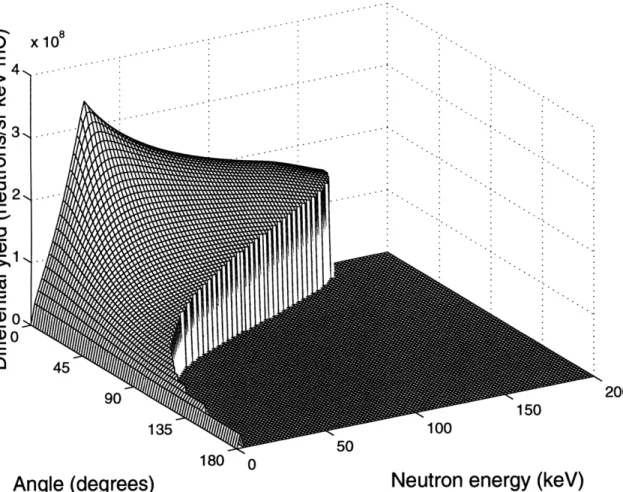
Figure 2-2: Differential Neutron Yield for 1.95 MeV Protons Incident on Natural Lithium Metal.
and C. Note that li. f can calculate thick target yields for natural lithium metal as well as certain lithium compounds; modifications of yield calculations for compounds is discussed in Section 2.2.4 below.
2.2
Calculated and Experimental Results
2.2.1
Thick Target Neutron Yield Surface
Figure 2-2 shows an example of a thick target differential neutron yield surface for 1.95 MeV incident proton energy. Note that the techniques described in the previous section have resulted in a smooth behavior of the yield surface in all regions of the
calculation. An irregular, jagged boundary edge between zero and non-zero yields is 38
400 ' ' 1 1 ' 1 1 1 1 400 O0 CO) C '. -O 200 C I " 100 - _ '4-
I
I Present Method (calculated) % - - - Liskien and Paulsen Data
I I
II (calculated)
1 O Kononov (experimental)
0 25 50 75 100 125 150
Neutron Energy (keV)
Figure 2-3: A Comparison of 0' Thick Target Neutron Yields.
apparent in Figure 2-2, which occurs because the yields are evaluated on a square array of grid points. There is actually a smooth line between the zero and non-zero values at the edge of the yield surface, which is the yield due to protons with an energy of precisely Epo, but because this line does not intersect the grid points where computed yield values are displayed, it is not visible as a smooth edge. The computer program is designed to calculate the location of this edge and the corresponding differ-ential neutron yields, so that energy spectra and angular distributions are integrated smoothly.
Figure 2-3 is a plot of the 0' thick target differential neutron yield for neutron en-39
ergies between 0 and 150 keV, corresponding to an initial proton energy of 1.94 MeV. The calculations described previously have been modified in this plot to predict neu-tron yields for 7Li metal, rather than natural lithium. The 0O differential yield shows
good agreement with experimental data given by Kononov [43]. Error bars for these data were not given in the original reference. The rounding of the yield curve at threshold can be explained by the proton beam energy spread. For comparison, the same quantity is plotted using the tabulated data of Liskien and Paulsen for energies below 1.95 MeV in order to demonstrate the mathematical pathologies that occur near threshold.
2.2.2
Thick Target Energy Spectra and Angular
Distribu-tions
It is straightforward to calculate thick target neutron energy spectra and angular distributions by integrating Eq. (2.2) over solid angle and energy, respectively:
dY (. (Epo) d2
(E) m27 x(Ep d (, E,) sin 0 dO (2.19)
dE, Jo dQ dE
dY
E = ,ma(Epo)d
2(0) (E= d2y (0, En) dE, (2.20)
dQ Enmzn dQ dE,
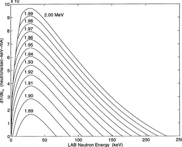
Thick target neutron energy spectra produced for near-threshold energies using Eq. (2.19) are shown in Figure 2-4, which gives the energy spectra for incident proton energies in steps of 10 keV between 1.89 MeV and 2.00 MeV. Note that there is no unusual behavior around 30 keV (En at the reaction threshold), where other yield computation techniques can produce erroneous spikes due to the infinity in the Jacobian product. The accuracy of these energy spectra should only be limited by the accuracy of the experimental cross section data, the nuclear masses, the mass stopping power, numerical roundoff error, and errors incurred by integrating using
x 10 10 1.99 2.00 MeV 1.98
-
1.97
E 7
1.95
i6-5- 1.92
" 4 1.91 UJ 3 1.90 2 - 1.89 1 0 0 50 100 150 200 250LAB Neutron Energy (keV)
Figure 2-4: Near-Threshold Thick Target Neutron Energy Spectra for Natural Lithium Metal.
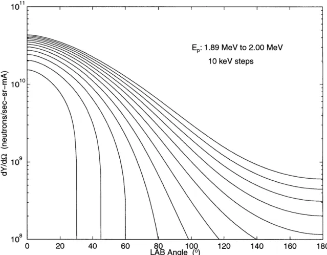
1011 E 1010 0 C -Cl) 0 10 0 1 0 8 1 0 20 40 60 80 100 120 140 160 180 LAB Angle (0)
Figure 2-5: Near-Threshold Thick Target Neutron Angular Distributions for Natural Lithium Metal.
the trapezoidal method, all of which are expected to be small.
Figure 2-5 gives the thick target neutron angular distributions for incident proton energies between 1.89 MeV and 2.00 MeV. These distributions were determined as shown in Eq. (2.20). A logarithmic scale has been used for the angular distributions in order to show the extremely low yields in backward emission directions. For incident proton energies below E*, no neutrons are produced for angles greater than Omaz (Epo),
as expected.
It is important to note that while the differential neutron angular yield, dY/dQ(O), with units of neutrons/sr mC, in Figure 2-5 is peaked in the 00 direction, the peak in the actual neutron emission spectrum in the LAB will not be in the forward direction.
x 1010
10 I I I I
9-8- Ep: 1.89 MeV to 2.00 MeV
7 - 10 keV steps I 6-1 5 0 S4 - 2-0 0 20 40 60 80 100 120 140 160 180 LAB Angle (0)
Figure 2-6: Near-Threshold Thick Target Neutron Angular Yields for Natural Lithium Metal. These yields, with units of neutrons/degree mC, are obtained by multiplication of the angular distributions of Figure 2-5 by the solid angle differential element.
In fact, there will be NO neutrons emitted in the 00 direction. This may be seen in Figure 2-6, where the angular distributions of Figure 2-5 are multiplied by the 27r sin 0 term from the solid angle differential element. The differential neutron yield in Figure 2-6 is therefore given in units of neutrons/degree mC, and the neutron yield between two angles 01 and 02 is simply given by the integral of this new yield function over 0. The sin 0 term from the solid angle element forces the yield to go to zero in the forward direction, and the maximum yields in the near-threshold region are seen to be in the 200 to 400 range.
Table 2.1: Near-Threshold Thick Target Neutron Yields for Natural Lithium Metal Incident Proton Total Maximum Mean Maximum Mean
Energy Neutron Neutron Neutron Neutron Neutron
Yield Energy Energy Angle Angle
(MeV) (n/sec/mA) (keV) (keV) (degrees) (degrees)
1.89 6.34 x 10⁹ 67.1 34.0 30.0 16.5 1.90 1.49 x 10¹⁰ 87.6 38.3 45.2 23.0 1.91 2.41 x 10¹⁰ 105.3 42.4 60.3 27.8 1.92 3.35 x 10"o 121.4 46.5 180 31.9 1.93 4.30 x 10¹⁰ 136.6 50.6 180 35.3 1.94 5.25 x 10¹⁰ 151.1 54.4 180 38.3 1.95 6.21 x 10¹⁰ 165.1 58.1 180 41.0 1.96 7.16 x 10¹⁰ 178.8 61.6 180 43.5 1.97 8.12 x 10¹⁰ 192.1 65.0 180 45.6 1.98 9.08 x 10¹⁰ 205.1 68.4 180 47.6 1.99 1.00 x 10¹¹ 218.0 71.7 180 49.4 2.00 1.10 x 10¹¹ 230.6 75.1 180 51.1 2.10 2.13 x 10¹¹ 350.4 108.4 180 63.0 2.20 3.62 x 10¹¹ 463.4 158.9 180 68.7 2.30 5.78 x 10¹¹ 573.1 233.1 180 66.3 2.40 7.48 x 10¹¹ 680.6 286.5 180 63.8 2.50 8.83 x 10¹¹ 786.7 326.4 180 62.9
2.2.3
Thick Target Total Neutron Yields
Integrating the thick target differential neutron yields over solid angle gives the total neutron yields for the various
both neutron energy and incident proton energies. Table 2.1 gives total thick target neutron yields, maximum and mean neutron energies over all angles, and maximum and mean emission angles over all energies.
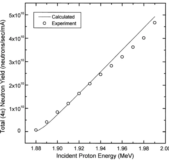
Experimental verification of the total (47r) neutron yields for natural lithium metal are shown in Figure 2-7. A major concern in these measurements was the formation of a corrosion product layer on the lithium surface which could seriously impact the yield measurement (see Section 2.2.6). In order to remove this effect, the lithium target was formed inside the accelerator beam tube under vacuum. A piece of lithium was placed in a small wire cage at the base of a stainless steel (type 304) backing inside
6x1 010 Calculated 0 < 5x101°O o Experiment
E
0 310 o 2x10'0 z0-%
R 1x10 '0 0 1- 0 1.88 1.89 1.90 1.91 1.92 1.93 1.94Incident Proton Energy (MeV)
Figure 2-7: Calculated and Experimental Total Neutron Yields for Thick Lithium Metal Targets
a Van de Graaff beam tube. The cage was placed below the proton beam area so as to not interfere with the beam once irradiation began. The wire leads were attached outside the tube to a Variac voltage controller. Once a vacuum was established in the beam line, the Variac voltage was increased, vaporizing the lithium in the cage and depositing it on the stainless steel backing. Deposition times were increased until yield measurements no longer indicated that partially thick targets were being formed for the initial proton energy range of interest (see Section 2.2.5 below). This criterion was satisfied when the Variac voltage remained on for 10-15 minutes.
The total neutron yield was measured using a 47r detector [25] employing 12 18-inch long 3He thermal neutron detectors. The counter, shown in Figure 2-8, was designed to have a flat neutron detection efficiency for neutron energies up to 100 keV [2]. The end flange of the beam line was placed at the midpoint of the central hole of the counter, and a paraffin plug was placed in the other end. The counter was calibrated before each measurement using a standard AmBe source. The relative error of each data point in Figure 2-7 is about 5%, primarily due to fluctuations in the energy of the proton beam.
2.2.4 Application to Lithium Compounds
It is a relatively simple matter to modify Eq. (2.18) to predict neutron yields in lithium compounds. We need to change the Aeff term to correspond to the molecular weight of the lithium compound, and in addition it is necessary to multiply by n, the number of lithium atoms per unit cell of the compound. For example, in the case of lithium oxide, Li20, there are two lithium atoms per molecular unit, so n = 2 in this case, and the molecular weight of Li20 is now used for Aeff. Unless the 7Li
enrichment is changed, fL-7 will not change. The only other change in calculating yields for lithium compounds is in the mass stopping power, which in the absence of experimental data must be estimated from the addivity rule for stopping powers. Our
1
-
20'
-18'
Figure 2-8: Schematic of Long Counter Used to Measure Total Neutron Yields for Lithium Compounds [2]


![Figure 2-8: Schematic of Long Counter Used to Measure Total Neutron Yields for Lithium Compounds [2]](https://thumb-eu.123doks.com/thumbv2/123doknet/14686197.560314/47.918.116.768.280.845/figure-schematic-counter-measure-neutron-yields-lithium-compounds.webp)