Design of a Silicon Wafer Breaker by
Kabir James Mukaddam
Submitted to the Department of Mechanical Engineering in Partial Fulfillment of the Requirements for the Degree of Bachelor of Science in Mechanical Engineering
at the
Massachusetts Institute of Technology January 2005
© 2005 Massachusetts Institute of Technology All rights reserved
..AFIOH V,., . - -,'
Signature of Author
Department of Mechanical Engineering January 19, 2005
Alexander Slocum Professor of Mechanical Engineering Thesis Supervisor Certified by
Accepted by
Ernest Cravalho Professor of Mechanical Engineering Chairman, Undergraduate Thesis Committee
Design of a Silicon Wafer Breaker by
Kabir James Mukaddam
Submitted to the Department of Mechanical Engineering On January 19, 2005 in Partial Fulfillment of the Requirements for the Degree of Bachelor of Science in
Mechanical Engineering
Abstract
Usually multiple MEMS or IC devices are fabricated on a single silicon wafer. Manually separating the components from each other involves scribing and fracturing the silicon. This thesis presents a design for a tool to aid in controlling the fracturing process. An earlier
prototype of this tool was examined and new functional requirements were described. One of the functional requirements is that the tool cannot touch the top of the wafer because the top might have delicate components. The wafer breaker was designed to hold the wafer on two plates, where one of them is hinged. The wafer is scribed above the hinge line, and the hinged plate is pushed down to fracture the wafer. Several methods of holding the wafer down with vacuum were investigated. Bench level prototypes were constructed to test the feasibility of the methods. The prototype with a grid of pockets and flow restrictors performed the best. Even when the wafer only partially covered the grid, the covered pockets maintained a high vacuum. A clamped flexure was used as the hinge for the tool. The instant center of the hinge was calculated for small deflections, and was aligned with a scribe guide. This forces the scribed notch to be directly above the hinge line. A prototype wafer breaker was constructed and tested. The prototype worked, but in many cases where the (111) silicon plane was not parallel or orthogonal to the scribe line, the crack line would leave the scribe line and follow the crystal plane. This problem would also be encountered by those manually breaking wafers.
Thesis Supervisor: Alexander H. Slocum Title: Professor of Mechanical Engineering
Acknowledgments
I would like to thank Professor Alexander Slocum for guiding me for the past 3 years. He has given me great opportunities to work on projects I really enjoyed. He proposed many of the ideas that were investigated for the new wafer breaker.
I would also like to thank Anastasios John Hart for all the time he worked with me. John is a pleasure to work with. His insights offered on the wafer breaker project were extremely useful. Lastly, Fred Cote has been helping me with every project I have brought into the machine shop since my sophomore year in high school. He is a great resource and an even better person. Thanks.
Table of Contents
1. Introduction ... 5
1.1 Silicon Wafer Technology ... 5
1.2 Wafer Cutting Options ... 5
1.3 Limitations of Existing Methods ... 6
1.4 Previous W ork ...7
2. Functional Requirements ... 8
2.1 The Tool Cannot Touch the Top of the Wafer ... 8
2.2 Accommodate Different Wafer Shapes ... 9
2.3 Align Scribe Line with Hinge ... 9
2.4 Provide Even M om ent ...9
3. D esign D ecisions ...9
3.1 Wafer Holding Options ... 9
3.2 Bench Level Prototypes ... 12
3.3 Hinge Options ... 18
3.4 Fram e Options ... 21
4. Detailed Design ... 22
4.1 Design of pockets...22
4.2 Design of Flexure ...25
4.3 Design of Multipurpose Clamp ... 29
4.4 Design of Small Clamp ... 31
4.5 Design of Preload Flexure ... 33
4.6 Design of Scribe Guide ... 34
4.7 Overall Design ... 36 5. Results ... 38 5.1 Prototype ... 38 5.2 Testing ...41 5.3 Problem s ... 43 6. Future W ork ... 44 7. Conclusion ... 45
1. Introduction
1.1 Silicon Wafer Technology
Many things are made with silicon wafers, including computer chips and MEMS devices. Because the size of each component is much smaller than the wafer it is produced on, multiple
components are made on one wafer. Often researchers can vary certain parameters for each component on the same wafer. Although the cost of the wafer itself is relatively low, the cost of the labor and machine time to produce a wafer with the components is very high. The final cost
is usually between $1000 and $10,000. Since the components are often used individually they need to be separated from each other. These individual components are called die. Although the
separation process is often a simple one, it must be reliable because the cost of breaking a component is so high.
1.2 Wafer Cutting Options
There are several ways to remove die from the wafer. One way is using die saw. This is a diamond saw, which is usually computer controlled. The saw runs in water to cool it and to wash the chips away. The wafer is attached to an adhesive tape that holds the die down while the saw cuts them out.
Another method is to fracture the wafer. This method is very similar to the way glass is cut. A sharp notch is cut into the wafer with a diamond tipped scribe. The scribe can be run along a ruler so that the notch is straight. Then the wafer is held down on the edge of a surface so that the edge of the surface lines up with the scribe line. The unsupported edge is gently pushed down by hand until the wafer fractures. The crack tends to propagate from the notch
because of the stress concentration created at the sharp point. The notch can also be etched during the component fabrication process.
1.3 Limitations of Existing Methods
For some applications the above methods are not appropriate or ideal. One example of an application where die saw will not work is for MEMS valves with exposed ports. When the die
saw cuts the silicon, it creates chips that are carried away by the water. Some of the slurry can get into the component and clog it with tiny chips.
The fracture method is more appropriate for these components because the fracture process creates very few chips. The problem with the fracture process is that it adds a human variable. It requires some skill to cut the die reliably. Sometimes the break does not follow the desired line and cuts through a component. Even if this does not happen often, the price of a mistake is high enough to justify spending money on a tool to facilitate the process.
The causes of the break line to deviate from the desired line include not having a proper notch. If the diamond tool is dull or the scribe is too light then the notch will not be sharp enough. A rounded notch does not provide as much stress concentration as a sharp one and the crack may initiate at some other place. Another source of error is when the scribe line is not
straight. Then the crack may initiate at one part of the notch, but then leave the scribe line. When the wafer is placed at the edge of a surface the scribe line should be directly above the edge. If it isn't, the crack may follow the edge of the surface instead of the scribe line. The moment acting on the wafer to fracture the wafer should have an axis parallel to the scribe line. If an off-axis moment is placed on the wafer, the fracture line may follow a line parallel to the axis of moment instead of the scribe line.
1.4 Previous Work
Victor Figueroa did his undergraduate thesis for Professor Alexander Slocum on designing and making a wafer breaker tool. This tool was designed for breaking six inch wafers. The purpose of the tool was to improve the reliability of the fracture process. One of the important
requirements of this tool was that it should not touch top of the wafer. This is because there are often delicate components on the top of the wafer. To improve the reliability of the process the wafer breaker was designed to provide an even moment on the wafer at the scribe line. This way, the user can align the scribe line with a line on the tool and thus ensure that the axis of the moment is parallel to the scribe line.
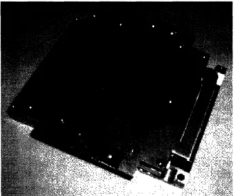
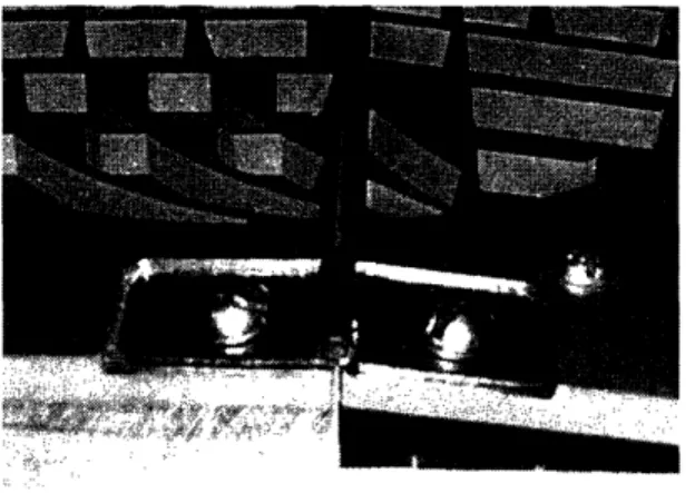
Figure 1. Old wafer breaker, designed by Victor Figueroa.
Victor Fiqueroa's tool used suction produced by a small vacuum pump to hold the wafer to two surfaces. One of the surfaces was attached to the base and the other surface was attached to the first with two hinges. The hinge axis was aligned with the surface of the top plates. The top plates were cut with a waterjet to create the pockets which contain the vacuum. Under each
of the top plates of aluminum there is another plate which feeds the vacuum to each pocket. This feed plate has a port for the tube from the vacuum pump and a series of horizontally drilled holes
to distribute the vacuum to the pockets. Between those two pieces there is a rubber gasket to isolate one pocket from another. Under the end of the hinged piece there are springs that keep the hinged piece horizontal until it is pressed to break the wafer.
When the wafer has been cut once, the shape that needs to be held down is no longer a circle. The pockets are shaped so that they can accommodate different configurations of a wafer. Small bars with o-rings glued to them can be pushed into the horizontal drill holes to close off certain pockets. Thus if the wafer is not covering all of the pockets, the open pockets can be closed.
The old wafer breaker needed to be refined to make it a more useful and reliable tool. One of the major problems with it was that it could only accommodate a small number of wafer
shapes. Since the wafer changes shape each time it is cut, the tool wasn't very useful. One solution proposed was to waterjet top plates for each set of cuts, but making and replacing the plates would be tedious. Another issue with the old wafer breaker was that there was potential
for human error in aligning the scribe line with the hinge line. Thus there was a need for the design of a better wafer breaker.
2. Functional Requirements
Before an improved wafer breaker can be designed, the functional requirements must be defined. The functional requirements of the new wafer breaker are not necessarily the same as those of the old one. Minimizing cost is a functional requirement but not a priority.
2.1 The Tool Cannot Touch the Top of the Wafer
The first functional requirement is that the tool cannot contact the top of the wafer. This
by the tool. Although not all wafers will have delicate top surfaces, the tool will have wider uses if it can fulfill this requirement.
2.2 Accommodate Different Wafer Shapes
Different size die will be cut on this tool, and once the wafer is cut it will have a different shape. Thus the tool will have to be able to break many different shapes of wafers. The tool must also be able to quickly adapt to the new shapes. If the user has to spend too much time setting up the tool, the user will likely prefer to cut the die by hand instead.
2.3 Align Scribe Line with Hinge
The tool should have some way to align the scribed notch with the hinge line. Ideally this will eliminate the human-introduced error in aligning it by hand. This also includes aligning the wafer with the hinge in the vertical direction. The optimum alignment would be to have the hinge centered on the bottom surface of wafer (assuming that the notch is on the top).
2.4 Provide Even Moment
The tool must aid the user in exerting a moment on the wafer that has an axis parallel to the axis of the scribe line. This will help keep fracture line aligned with the scribe line.
3. Design Decisions
3.1 Wafer Holding Options
Since one of the functional requirements is that the tool cannot touch the top of the wafer, the tool needs a different way to hold the wafer in place while it is scribed and broken. We decided to use vacuum to hold the wafer down as in the old wafer breaker. Several methods to create the
3.1.1 Pockets with closeable ports
The old wafer breaker firmly held wafers of specific shapes but was not easily adaptable to other shapes. To make that method more adaptable, the few shaped pockets can be replaced with a grid of small pockets. Each of the small pockets would have a way to block the vacuum supply to that pocket. A small rubber plug could be inserted in the supply hole to each pocket that is not
covered by the wafer. This way the tool can accommodate different wafer shapes.
The benefits of this method are that it is simple and it has been tested in the earlier
version. It will also probably provide a high vacuum because any pocket that is not sealed by the wafer can be closed off. One drawback of this method is that the plugs would be easily lost. Another issue is that it would be tedious to figure out which pockets would be uncovered by the wafer and to cover them with the plugs.
3.1.2 Pockets with flow restrictors
One way that the user would not need to make any changes to the tool for a different shape of wafer is if the all of the pockets on the wafer are always pulling a vacuum. Since even the pockets that are uncovered by the wafer will be connected to the vacuum source, flow restrictors will have to be installed to prevent the flow from becoming too high. Each pocket will need its own flow restrictor because each pocket must be isolated from the others. If there was a single flow restrictor in the source there would be no unrestricted flow path between covered pockets and the atmosphere. Since the user would not have to cover pockets individually, there could be a grid with a large number of pockets.
This method has the benefit of allowing for any shape as long as it is large enough to cover at least one pocket. One of the drawbacks of using flow restrictors to limit the amount of flow is that there will always be some flow out of the open pockets. This will decrease the
driving vacuum on the closed pockets. There will also be some pressure drop across the restrictors, which will decrease the vacuum in the pockets. A problem with any method involving pockets is that if the wafer only partially covers a pocket, there will be no holding force on that part of the wafer. This could cause the crack to wander on the unsupported part of the wafer. One solution to this problem is to make the pockets small enough to create an effectively even support.
3.1.3 Pockets with variable flow restrictors
Ideally the flow should be restricted as much as possible to the open pockets and as little as possible to the pockets covered by the wafer. This way the total flow will be low, causing the vacuum behind the pockets will be high. At the same time the pressure drop between the covered pockets and the supply will be small. One way to achieve this behavior is for each pocket to have a small lever. When the wafer is placed on the pocket, it pushes on the lever, which opens the port to the vacuum supply. The problem with this is if the wafer is only half-covering the pocket, the lever will get activated and the vacuum source will be open to the atmosphere.
A more feasible design would involve a porous flexible membrane. The membrane would be stretched across the opening to the pocket. The pocket would have a small hole feeding the vacuum to it. When there is no wafer on top of the pocket, the membrane would get sucked down over the small feed hole. Thus the flow, which is proportional to the area of the porous material it can pass through, would be small. When the wafer is placed on top of the pocket, the
space between the membrane and the wafer begins to hold a small vacuum. This allows the membrane to spring back to its original position and thus exposing a larger area of membrane
Variable flow restrictors will reduce the necessary flow and increase the vacuum on the wafer. The main problem with them is that they increase the complexity of the tool, especially if there are many pockets.
3.1.4 Porous material
The more pockets that the tool has, the more even the hold will be. Laying the wafer on a porous surface with air being pulled from below the surface provides an even vacuum under the wafer. Like the pockets with restrictors, the parts of the porous surface that are not covered by the wafer will allow some flow. The ideal porous material would be anisotropic, with much higher
porosity through its thickness than in the lateral direction. If the material is too porous in the lateral direction, the air will be pulled laterally through the material below the wafer instead of being pulled from the surface under the wafer.
This method has two major benefits. The first is that it will provide an even holding force on the wafer. The other benefit is its simplicity. Creating a vacuum fixture would only require a plate of porous material and a cavity behind it for the vacuum to feed into. Like the pockets with flow restrictors, the material would need to be optimized to maximize the vacuum between the wafer and the surface of the porous material.
3.2 Bench Level Prototypes
A quantitative analysis of the different holding methods would have been difficult because so few of the parameters are known in this case. Instead, bench level prototypes were constructed to determine which holding option would be the most appropriate for the tool. These are not prototypes of the whole system, but prototypes of some aspect of the tool which reveal the feasibility and difficulties of each method.
The prototype of a the closeable pocket method was simply a series of small pockets milled out of a piece of scrap plastic. A hole was drilled in the bottom of each pocket and tapped on the other side, to connect the tube supplying the vacuum.
Figure 2. Bench level prototype of pocket design
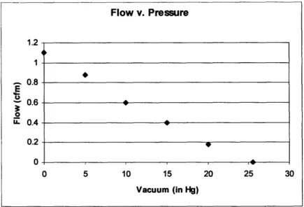
The vacuum was measured with a vacuum gauge on the pump. The vacuum pump used was a Gast diaphragm pump model DOA-P104-AA. The flow could be estimated from the measured pressure using the flow versus pressure plot.
Figure 3. Approximately linear relation between pressure and flow from the Gast diaphragm vacuum pump. Data source: http://www.gastmfg.com
A couple important observations were made. The step above the pocket, where the wafer rests, was milled, so the surface finish was not very smooth. Despite this the wafer sealed well to the plastic and a high vacuum was maintained. Another observation was that simply laying a piece of rubber on the feed hole was sufficient to effectively stop the flow. Thus the user could lay a piece rubber over every open pocket's feed hole. The main problem is that the little pieces of rubber would get lost. The closeable pocket option would work, but it would not be an
elegant solution to the problem. 3.2.2 Flow restrictor prototype
In this test, small pieces of paper were used to cover the feed holes on the closeable pocket prototype in an attempt to close off the pockets. This method did not completely stop the flow,
but limited it to a very low level. When the wafer was placed on the pocket, the flow was high enough to create a relatively high vacuum in the pocket. This result led to the idea of using a porous material over small holes to create low-cost flow restrictor. The resistance could be
changed by varying the hole diameter beneath the paper. Then a bench level prototype of a set of pockets with paper restrictors was constructed.
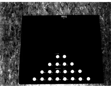
Figure 4. Bench level prototype of flow restrictor pocket grid.
A grid of 1/16" holes was drilled into a piece of acrylic. A small circle of paper, made with a hole-punch, was glued over each hole. Care was taken not to get glue on center of the paper circle so that air could flow through. A Dremel was used on the back side of the acrylic to make notches that connected the feed holes to a single supply hole. Then a piece of rubber was glued to the back to cover the notch. A grid of rubber was glued to the top to create the pockets.
This prototype did not require much flow, but still held the wafer down firmly. Because of high friction of the rubber, it was very difficult to slide the wafer around when the vacuum was turned on. This would be beneficial when the wafer was being scribed. When the wafer was pulled off the device, the rubber deformed slightly. This could be a problem because the deformation in the rubber may allow the crack to wander from the scribe line. Overall, these results were promising.
3.2.3 Variable flow restrictor prototype
To test whether the variable flow prototype was feasible, a small piece of paper was stretched over the plastic pocket from the first bench level prototype. This would simulate a flexible
material being pulled down to cover the feed hole. The paper was not elastic enough to perform well. If the paper was held tightly it would not be pulled down enough to cover the feed hole. Otherwise the paper did not have enough elasticity to pull away from the feed hole when the pocket was covered by the wafer. A more elastic porous material was needed for this method.
Not much time was invested in this test after the success of the fixed flow restrictor prototype. This method is more complicated and would be difficult to produce as the pocket size gets smaller. If the fixed restrictor method works, then this method has no benefits over it. 3.2.4 Porous material prototype
Initial experiments with holding the wafer down on a porous material were done using a porous graphite air bearing. Instead of supplying pressure to the air bearing, vacuum was supplied. There was very little flow through the air bearing, but it was able to hold the wafer with some force. However, the force was insufficient to break the wafers unless they were in large pieces.
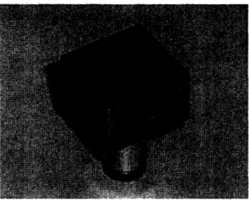
The porous material used to do the next bench level prototypes was porous aluminum. The porous aluminum was made by a sintering process, where tiny particles of aluminum were pressed together until they fused. The porous aluminum was bought in a 10mm thick sheet. The pore size was O.0006".2 The surface of the sheet was cut roughly so the aluminum had to be machined before it could be tested. A 1" square piece was cut out of the sheet and milled on both sides. A pocket was milled on the back side. A piece of scrap plastic was drilled and tapped so the tube connector could be attached. Then the plastic piece was glued to the back of the aluminum square. The pocket in the back of the aluminum created a cavity that supplied the vacuum. The sides of the aluminum square were coated with epoxy to prevent air flow through the sides.
Figure 5. Porous aluminum test piece.
Machining the porous aluminum required some care. The material is very soft. This is probably because the individual particles are not attached to each other as well as they would be if they were a single piece. In addition, the air space in the material provides room for the aluminum to be compressed. To maintain open pores on the surface, the aluminum must not be
"smeared". If the cutting tool is dull it has a tendency to push the material away instead of cutting it off. In the case of the porous aluminum, this pushes the particles into adjacent holes. It
is therefore important to use as sharp a tool as possible. Also, when the cutting tool depth of cut is small, the material tends to push out of the way instead of being cut. Thus, too light a cut can also cause the pores to close. When the cutting tool is spinning as in the case of an end mill or fly cutter, the cutting edge will pass over a region several times depending on the feed rate and the spindle speed. Each time it passes over it cuts a little, but these light cuts tend to smear the particles across the surface. Thus to keep the pores for closing, the feed rate should be
maximized and the spindle speed should be minimized. The tradeoff is that these requirements cause a rough surface finish.
After some experimenting with the different parameters, an adequate surface finish was achieved with a sharp fly cutter while still maintaining open pores. Tests on the 1" square
revealed that despite a larger flow, the porous aluminum did not hold the wafer as firmly as the air bearing did. This was likely because the surface finish on the aluminum was not as good.
To simulate a larger area of porous aluminum two other prototypes were constructed. The flow rate through even the thicker of the two prototypes was higher than desired. Despite the high flow rate, very little holding force was observed. The suspected cause of this
unexpectedly low force was that air could flow laterally along the boundary between the wafer and the aluminum. The porous surface created tiny channels that allowed the air to flow along the boundary easily. Another factor might be the porosity of the porous aluminum. It was porous enough that the sheet had to be thick to get the desired resistance. This means since the material was generally isotropic, the air could flow around the area covered by the wafer, and not as much air would be pulled from the surface below the wafer. Although using this porous material would have been the ideal solution to holding down the wafer, the porous aluminum did not work as planned. As a result the fixed resistance flow restrictor method was decided upon.
3.3 Hinge Options
Once the wafer is held down to the fixed and hinged surfaces of the tool, the user presses on the hinged surface to exert a moment on the wafer. There were three options considered for
connecting the hinged surface to the fixed one. 3.3.1 Pinned hinge
The earlier wafer breaker used flat pinned hinges to connect the two surfaces. These hinges have a large range of motion and are durable. On the earlier tool the hinges had to be inset into both of the surfaces so that its center of rotation would line up with the surface.
Figure 6. Hinge on old wafer breaker.
One benefit of the hinge is that it is very hard to break. The drawback of a hinge is that hinges usually have some looseness in them. Another drawback is that the center of rotation of a hinge is hard to find and align with the surfaces. Since the silicon breaks at very small deflections of the hinged surface, any looseness or misalignment could cause the silicon to break improperly. 3.3.2 Monolithic flexure
A hinge can be made out of a flexure. Given a certain load characteristic, a beam will have an instant center for small deflections. This means the beam will act like a hinge with a pin at the instant center. The flexure could be made out of the same material as the surface plates. Then the fixed and hinged surfaces would be the same piece. The two surfaces would be connected by a flexure that was machined from the part.
Figure 7. The thin flexure is machined out of a plate to create a hinge
This monolithic flexure has the benefit of already being aligned with the two plates. The limitation of the monolithic hinge is that it must be made out of the same material as the plates that they are attached to. Thus it would have been very difficult to make a monolithic flexure using the porous aluminum plates because of the porous nature. The sintered material is made of particles pushed together with gaps in between, so the material will fracture easily along the interfaces between the particles. Thus the flexure would probably be made out of solid aluminum because aluminum is the preferred material for the fixed and hinged plates. 3.3.3 Clamped flexure
The alternative to a monolithic flexure is a clamped flexure. This type of flexure is where the flexure material is clamped to both the fixed and hinged parts. The flexure can be made of any material. Spring steel is traditionally used for these flexures. It also has the advantage of being
easily fixed if the flexure is damaged. The main drawback of the clamped flexure is that it must be aligned to both parts. The clamping assembly also adds complexity to the tool. Despite its
drawbacks, the clamped flexure was chosen for the hinge because it is more durable than the monolithic flexure and is easier to align than the pinned hinge.
3.4 Frame Options
The decision on the type of frame for the tool was as much an aesthetic one as a practical one. The options considered were a tool with a large base with several components, and a tool with a few parts that would serve multiple purposes.
3.4.1 Large base
This design would be similar to the design of the frame from the old wafer breaker.
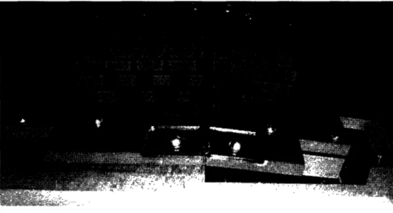
Figure 8. Old wafer breaker sits on a base of aluminum
The base of the old wafer breaker was a large piece of aluminum. On top of this part was another plate that fed the vacuum to the pockets of the fixed plate. The fixed plate was bolted down to the base through the intermediate plate with a rubber gasket in between. The rubber gasket prevented the air from leaking to one pocket from the adjacent ones or from the edge of the plate. The new design would need to have a guide for the diamond scribe, which would be mounted above the fixed plate. The new design would also need clamps on top of the fixed plate to hold the flexures down. The hinged plate would need similar clamps. Another functionality that the wafer breaker should have is that the top hinged plate should be coplanar with the top of
the fixed plate in its resting position. To do this the springs below the hinged plate would preload it against a locating surface, which would be aligned with the fixed surface. This locating surface would probably be attached to the base.
3.4.2 Multipurpose clamp
As an alternative to the above design, a single part could serve multiple functions. Because on each side the fixed clamp, the guide for the scribe, and the locating surface are all fixed, they could be combined into one part. This part can also extend below the fixed and hinged surfaces and act as a leg. The benefit of combining these parts is that they will then be located with respect to each other without any additional parts. This would make the alignment of the multiple functions much simpler than if each one were a separate part, and needed to be located to another part. Although the large base design has the advantage of adding weight to the tool, which would make it feel more solid, the multipurpose clamp looks more elegant. The
multipurpose clamp idea was chosen for its practical and aesthetic benefits.
4. Detailed Design
After choosing the concepts for each major component of the tool, the design for each one was finalized.
4.1 Design of pockets
4.1.1 Shape of Pockets
Because the flow restrictor method was chosen for supplying the individual pockets with air, the new tool can be designed with more pockets than the old wafer breaker. The shape of the new pockets would be a grid of rectangular holes. This way the individual die would be more likely
to cover a whole pocket, because the die are almost always rectangular. The rectangles would also allow for a better pocket area to surface area ratio than circular holes.
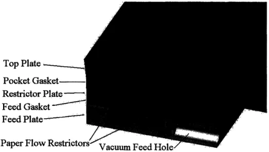
Rectangular pockets are difficult to make on the milling machine, so the fixed and hinged plates were designed to be cut on the waterjet. The waterjet can only cut accurately if it cuts through the part. So a separate plate to hold the orifices was mounted below the top plate to
form the pockets.
Top Plate. Pocket Gasket
Restrictor Plate -Feed Gasket
Feed
Plate
-Paper Flow Restrictc
Figure 9. Pocket assembly section view.
The added benefit of this is that the flow restrictor design can easily be altered without changing the top plate.
The final version of the wafer breaker has only two rows of pockets on each plate. This was decided because as long as the first two rows of pockets can hold the silicon flat, as would be necessary to cut a wafer piece that is only one or two pockets long, any pockets in rows farther away from the hinge would not have an effect on the stresses at the hinge. The same argument would imply that only one row is necessary if the tool is capable of breaking die that
are one row long. The only reason there are two rows is that the extra force will help hold the large pieces in place while scribing.
4.1.2 Top Surface
The flow restrictor prototype had rubber as the surface contacting the wafer. Rubber deforms enough that it makes a very good seal on the smooth silicon. This is probably why the flow in this prototype could be so low, yet the holding force was high. The old wafer breaker has
aluminum tooling plate as the top surface. Although the tooling plate is very flat, it doesn't create as good a seal as the rubber. As mentioned earlier, the rubber can deform as the moment
is exerted on the wafer, and thus the wafer will not be kept flat on the surface while breaking. This could allow the wafer to break at other places besides the hinge line. The new design incorporates the advantages of both the rubber and the tooling plate by putting a thin piece of adhesive backed plastic on top of the aluminum top plate. This particular plastic is usually used to hold wafers down while being cut on the die saw. Because the plastic is thin, it does not
deform much, yet it deforms enough to seal to the silicon. 4.1.3 Flow Restrictor Type
The two kinds of flow restrictor considered were the orifice type and the porous type. The orifice flow restrictor is simply a very small hole through which not much air can flow. The problem with this type of restrictor is that for the low amounts of flow required through each pocket, the orifice needs to be very small. This is difficult to do because to drill such a small hole, the drill bit needs to be rotating at extremely high speeds. Also, the small drill bits cannot drill very deep. The other option is to place a porous material over a much larger hole. This was the method used to make the flow restrictor prototype. The benefit of this model is that the resistance of the restrictor can easily be changed by varying the size of the hole under the porous
material. For the final prototype, three sets of restrictor plates were made with different size holes in order to determine the optimum resistance.
Paper was used for the final prototype. The main weakness of the paper restrictors is that they will tear if the silicon is rubbed across them. Paper was acceptable for the prototype
because the paper is inside the pocket and is somewhat protected from damage.
4.2 Design of Flexure
One of the key components of the wafer breaker is the flexural hinge. Both sides of the flexure are clamped to the fixed and hinged top plates. Although the flexure is only a thin rectangular piece of metal, substantial thought was put into its dimensions.
4.2.1 Instant center calculations
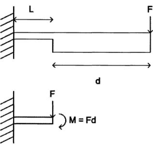
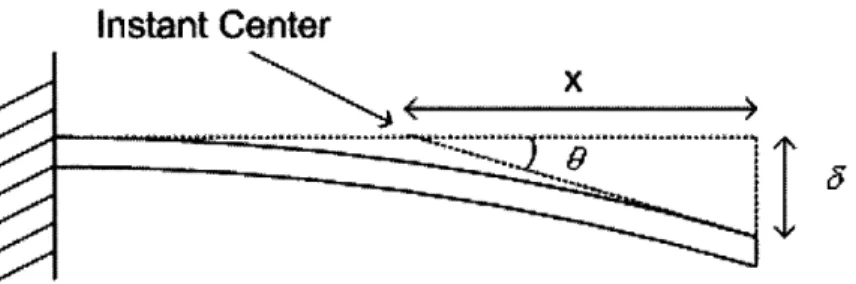
As mentioned above, the flexure acts like a hinge over small deflections. To calculate the position of the instant center with respect to the moving end of the flexure, the system must be characterized. The user will push on the end of the hinged top plate, which will be attached to the flexure. This will exert a moment and a force on the flexure.
L
E~~~~~~~~~~~~~~~~~~~~~~~~~~~~~
F.
I
d
) M = Fd
Instant Center
x
I
'5Figure 11. Parameters defining instant center for small deflections of beam.
The goal of these calculations is to find x, which is the distance between the instant center and
the moving end of the hinge. To do this, we need to find 6 and 0, since x =
8
. For small tan 08
angles, tan 0 so the above equation simplifies to x = Using standard beam bending 0
equations
aon it
=ML
2 32EI
FL3
= F._ for a beam with a force on the end. For a beam with a pure moment exerted
3EI
FL3 ML2
Using superposition the total deflection is = + . The same property
3EI 2EI
FL 2 ML
applies to the angle of the endpoint of the beam, so 0 = F +
2E
El
combined equation is x =
Recall that M = Fd so the
x = L( 2L 3d). Thus the instant center position depends only on the length of the beam and
3L+6d)
the length of the lever pushing on the beam. So as long as there is a fixed point where the user is exerting a force, the instant center will remain constant for small deflections. The hinge on the wafer breaker is expected to have a maximum travel of 5°. The brittle wafer will break well before the hinge reaches 5° . An important question is if the small angle approximation holds
FL3 FdL2
_+
3EI 2EI . After simplifying the equation becomes FL2 FdL
2EI EI
for5° . The error at5° is the difference betweentan0and0. max = 5°= 0.087264rad and
tan 0max = 0.087486, which is a 0.3% difference. This is an acceptable error for the instant center at the maximum deflection.
4.2.2 Flexure stiffness calculation
As the user pushes the hinged plate downward, the flexure will provide an opposing force proportional to the deflection and the stiffness. The flexure must be stiff enough to limit motion to rotation about its instant center, but also to feel solid so that the user will not be skeptical of the tool's quality. The preloading spring, which is the spring which preloads the hinged surface
against the locating surface, will contribute to the stiffness of the flexure, but for these calculations only the hinge flexures are taken in to account. 2N of force at the maximum deflection was taken as a reasonable number. Since there are two hinge flexures, each flexure would bear N. Using the beam bending equations we can find a thickness for the flexure that is
FL2 ML
appropriate for the requirements. Recall from the equations above, 0 = + -. After
2EI El
-d
te ngla
dflctonbeoms =FLL
substituting M = Fd, the angular deflection becomes 0 = EI 2 + d where I is the moment of
inertia about the z-axis and E is the Young's Modulus. In the case of a rectangular beam
bh3
I = 2, where b is the width of the beam and h is the thickness. Substituting the inertia into
12
12FL L 'te3
the above equation and solving for h gives h = I - + d . In this case 0 is the
ybE0 k2
maximum deflection and F is the force desired at that deflection. The width of the flexure, b, was decided to be 0.5" because the clamp should cover the whole width of the flexure, and the clamp was to be made out of 0.5" aluminum. L was arbitrarily set at 1". The distance d is
measured between the end of the flexure and the user applied force. Since the user applied force will be at the edge of the hinged top plate and the hinged top plate must be large enough to support more than half of the 6" wafer, d was set at 3.5". The material chosen for the flexure was blue tempered spring steel. This steel has a high yield stress and good flexibility. Using these parameters h = 0.0201". This means that the flexures could be cut out of sheet of 0.02" spring steel.
Now that the beam has been designed for stiffness, it must be checked for yield or fatigue. If the beam will be bent back and forth many times in the tool's lifetime, the flexures
should not fatigue enough to break. The fatigue will depend of the number of cycles, but for this application, a conservative criterion will be to have the maximum stress on the steel to be less
Mby
than 75% of its yield stress. The stress at any point in a beam is given by r = - - The
maximum stress will be at the base of the flexure where Mb = F(L + d). At that point in the h
beam the maximum stress will be at y = -, where y is the distance from neutral axis of the
bh3
beam. Recall that I = . So after substituting these equations into the stress equation, the 12
maximum stress becomes~~~~~~~~maxiu max stesbcmsCmax=bh= 6F(L + d). For this case, maximum stress is 2 amax = 205MPa,
which is less than half of the yield stress of the spring steel, which is Cryield = 550MPa (estimated
lower bound 4). Thus the flexure will not break due to normal use. If the flexure had been
yielding with the chosen parameters, some of them would have to be changed. The easiest way to increase stiffness without adding to the stress is to make the beam wider.
4.2.3 Hard stop design
The flexure has been designed to have a certain force at the maximum deflection of 5°, but if the user presses too hard, the flexure should not yield. So the tool should have a physical stop to prevent the flexure from bending beyond the maximum desired deflection. The convenient way to do this would to integrate a hard stop into the multipurpose clamp. The bottom surface of the hinged top plate would contact the clamp at 5. The problem with this is that if the thickness of the top plate is changed, the hard stop will stop the part at a different angle. This is not
acceptable because the tool's individual parts should be easy to replace with new designs. The other option is to have a bolt protrude below the hinged top plate and contact the ground at the maximum travel. Although this is not as elegant a solution, it does not require the top plate to be a fixed thickness.
4.3 Design of Multipurpose Clamp
The part that clamps the flexure to the fixed top plate serves many purposes. Every component of the wafer breaker that needs to be accurately placed is located through this part.
The clamp width was made to be 0.5" so it could be easily cut on the waterjet, and still wide enough to clamp a 0.5" flexure. The waterjet was used to cut the multipurpose clamp because it can easily create irregular shapes and is very fast. The waterjet also has some
limitations. The main limitation is that the waterjet creates a taper on the cut surface. The angle of the taper depends on many factors including the cutting speed, the material, and the condition of the nozzle. In this case the taper is approximately 1 . The kerf is wider at the top of material where jet first contacts it. This means that the top side of the part is accurate, and the other side
is subject to variances in the taper.
Figure 12. Profile of multipurpose clamp after being cut on waterjet. Once the clamp was cut, then the important surfaces needed to be milled flat.
Figure 13. Milled surfaces on multipurpose clamp.
The clamp surface lies 0.02" above the locating surface so that when it is clamping the flexure, the locating surface is aligned with the top surface of the fixed top plate. Thus when the hinged top plate is preloaded against the locating surface, the fixed and hinged top plates will be aligned. Since both surfaces were cut on the milling machine at the same time, they will be very accurate with respect to each other.
There are two press-fit holes for 1/8" dowel pins in the clamp. These pins locate the multipurpose clamp to the flexure and the fixed top plate. Sliding fit holes are made on the flexure and the fixed top plate, so the clamp can be easily removed.
Scribe Guide Hole .ss
Foot Mounting Hole
Figure 14. Other features of the multipurpose clamp.
The clamp has two tapped bolt holes so the clamp can be tightened down on the flexure. The foot mounting hole is a tapped hole for the threaded rubber feet. The scribe guide hole is a sliding fit hole for the scribe guide bar. To make an accurate sliding fit, the hole was first cut undersize on the waterjet. Then a drill press is used to drill the hole to the proper size, with care taken to start drilling from the accurate side of the hole. The drill press is used because the clamp must be held with some compliance so that the drill bit aligns the part to itself when it enters the waterjet hole. This prevents the drill bit from exerting lateral force and creating its own hole. This method was also used to create the sliding fit holes for the locating pins on the top plates.
Another feature of the multipurpose clamp is the small notch on its underside. This notch is meant to align the small clamp to the multipurpose clamp. The diameter of this notch is designed for a 3/8" dowel pin.
4.4 Design of Small Clamp
Locating Notch
lamp Bolt Holes Do elPin Hole
Figure 15. Small clamp features
The small clamp has only one press-fit dowel pin hole because its angle is determined by the locating notch. The dowel pin locates the hinged plate to the small clamp but remains unconstrained on the flexure because the dowel pin hole on the flexure is loose.
3VS, Dowel Pin "~-,.
Figure 16. Method to define distance between the multipurpose clamp and the small clamp during assembly.
During assembly the small clamp is attached to the flexure and the hinged top plate, but the bolts are not tightened. Then a 3/8" dowel pin is placed in the hole formed by both clamps. Thus the distance between the two clamps is defined and the bolts can be tightened. This distance is
important because it defines the unclamped length of the flexure, which defines the instant center. After assembly, the dowel pin is removed.
4.5 Design of Preload Flexure
The preload flexure must be stiff enough to preload the hinged top plate against the locating surface on the multipurpose clamp. The weight of the completed hinged assembly was unknown so a non-analytical method was chosen to determine the stiffness and preload of the flexure.
Fixed Top Plate Hinged Top Plate Preload Bolt
D ULA L:g
Figure 17. Preload flexure assembly before the preload bolt is lowered to create a preload.
The flexure is bolted to the back leg of the tool. The other end of the flexure extends under the hinged top plate. The preload bolt must be at the correct height so that the flexure contacts the ground at a hinge angle of 5. This places the preload bolt at a height where the flexure is deformed slightly when the hinged top plate is horizontal. The head of the preload bolt is the point where the user is supposed to push to break the wafer. This point was the point used in the instant center calculations, so the flexure must exert a force directly on this point or the instant center will shift. The preload bolt is not attached to the preload flexure because if the contact point could not change, the system would become over-constrained.
The preload flexure was designed to be 0.5" so that it fit the back leg, which is also 0.5" wide. Several identical spring steel flexures were cut on the waterjet. They were stacked to create a preload flexure of the desired stiffness. The benefit of making stacked flexures over a thicker flexure is that adding stiffness does not change the stress in the individual beams. Thus as long as a single beam will not yield for a given displacement, the layered beam will not yield. The other benefit is that the stiffness is easy to adjust because it is linear with the number of beams in the stack. For this case a stack of four 0.035" thick flexures was used to preload the hinged top plate.
4.6 Design of Scribe Guide
The scribe guide is designed to force the diamond scribe to travel in a straight line above the hinge line.
Diamond Scribe
Scribe Guide Bar /
Figure 18. Scribe guide assembly.
The guide bar is slid into the multipurpose clamps and then secured with bowed e-clips on either side. The bowed e-clips preload the guide bar against the clamps to eliminate any looseness. The
diamond scribe needs to be adjustable to accommodate different wafer thicknesses, so the
diamond scribe can be adjusted to the correct height. Once the scribe is at the correct height, it is secured by tightening the scribe clamp bolt. The scribe holder was designed to be able to rotate around the guide bar so that the user could push down on the scribe holder while moving it across the wafer.
4.6.1 Scribe guide bar stiffness
The user might inadvertently put lateral force on the scribe holder during the scribing process. To prevent this from moving the scribe line off of the hinge line, the system must be stiff enough. The system is the most compliant when the scribe holder is at the center of the guide bar. The guide bar will be modeled as simply supported because the sliding fits on the clamps and the scribe holder do not prevent small angular deflections.
1
I
T
Ih 4,.
L t. ~ ~ .
Figure 19. Simply supported model of the scribe guide bar deflection.
FL3 IID4
The governing equation is = - . The beam has a circular cross section, so I - where
48EI 64
D is the diameter of the guide rod. The maximum lateral force the bar is expected to take is estimated at 5N and L is 8". E = 207GPa for a steel rod. The original plan called for a '/4" rod, but calculating the displacement with these parameters, the deflection was a = 0.013", which is
greater than desired. Although it is unlikely that the bar will experience 5N of lateral force, the displacement for such a force should be under 0.005". Changing the guide bar from a /4" rod to
a 3/8" rod increases the diameter by 1.5 times, but decreases the displacement by approximately 5 times. With a 3/8" guide bar, the straightness error in the scribe line due to lateral forces should be negligible.
4.6.2 Scribe holder sliding contact
The reason that the 1/4¼" guide bar would have been desirable is that the scribe holder would have
been less likely to jam than on the 3/8" bar. To prevent the tool from becoming too wide, the scribe holder's width was set at 1". Ideally, the ratio of width of the scribe holder to the diameter of the shaft that it rides on would be 3:1 or higher. 1 As this ratio gets lower, the tendency for the scribe holder to jam under off-center loads increases. The 3/8" rod gives a ratio of 8:3, which is acceptable. The scribe holder was originally going to be made with Delrin, but the Delrin was soft enough that it jammed. Instead, the scribe holder was made with aluminum.
4.7 Overall Design
After the functional components were designed, the remainder of the design was driven by aesthetic considerations.
Figure 20. Final tool design.
The corners cut out by the waterjet were rounded where possible to give the tool a more polished look. The rubber feet were added to the legs to prevent the tool from sliding around during use.
5. Results
5.1 Prototype
After the detailed design was finished, the prototype was fabricated.
Figure 23. Finished prototype.
The thin sheet of plastic over the pockets is adhesive backed. The plastic was cut by hand and put over the pockets. Then a hole was punched in the plastic over each of the pockets to let the air through.
The construction of the prototype required relatively few steps because most of the machining was done on the waterjet. The only unexpected problem was that while the waterjet was cutting out the pockets, each rectangle of leftover material tended to tip on its side. This caused the waterjet nozzle to collide with the rectangles and push the plate out of position, and the part needed to be started again. To solve this problem, the nozzle was programmed to move out of the way as soon as each rectangle was freed. The rectangle was removed by hand before the cutting was resumed.
The only error found in the prototype construction was that the multipurpose clamps were very slightly set back from the edges of the fixed top plate that they were supposed to be aligned with. This was probably because the dowel pin holes could have been referenced to the
inaccurate side of the taper when they were being drilled onto the clamp. The error in the prototype matches in direction and magnitude with this theory.
Figure 25. Side view of prototype.
As can be seen from the side view, the hinged top plate is contacting the locating surface and is parallel to the fixed top plate. The error in the position of the multipurpose clamp is small enough that it can't be seen in the above photograph.
5.2 Testing
The prototype was connected to the vacuum pump and the pressure was read on the pump to obtain an estimate for the flow rate. The vacuum was approximately 17inHg which corresponds to a flow rate of approximately 0.3cfm. This was using the largest restrictor hole diameter of
1/8". One important observation was that the flow was not uniform from one pocket to another. There was a substantial difference between flow rates through the paper orifices. This effect was most easily observed when the top plates were not covered with plastic. Since the bare
maintained a substantially higher vacuum in their pockets. When a small piece of wafer is passed over the pockets one by one, there is a noticeable difference in holding force from one to the next. When the plastic was installed on the surfaces, the seal was good enough that these differences were much less noticeable.
The prototype was tested on 700 micron 150mm silicon wafers. The first observation was that when the silicon wafer is placed over several pockets, it becomes very difficult to move unless the vacuum is off. The wafer was placed on the tool and the vacuum was turned on. Then the wafer was scribed with the guided scribe. The wafer was held down firmly enough so that the force from the scribe did not move it. Then the user pushed gently on the bolt head and the wafer cracked at a very small deflection. The crack was along the scribe line as expected. The surface finish on the fractured surface was relatively rough. This implies that the wafer was not cracked along a crystal plane.
Figure 26. Successful cuts on a wafer.
The silicon is predisposed to crack along the crystal planes, and when it does, the surface finish on the fractured surface is very smooth.
Many more cuts were made with the tool. The most important observation was that the wafer would not always break along the scribe line. When the scribe line is not aligned with the
(111) crystal plane, and especially if some portion of the wafer is not supported, the crack sometimes leaves the scribe line and propagates along the crystal plane.
(111) Plane
Scribe Line /
- . .- . . ...- - --- ... . . I. ... - .. .. -..
Figure 27. Case where the crack leaves scribe line and follows the crystal plane. Luckily, most die are aligned with the crystal planes because the planes are used in the etching process. Thus in most cases the wafer will have to be cut along the crystal plane.
The tool held the wafers down well, despite the differences in flow between the pockets. There were some cases where certain smaller shapes could not be cut because they were too
small for the pockets.
Overall, the tool was successful. It worked as it was supposed to. It had no problem with the differently shaped wafers, except for the ones that were less than l"xl". The main drawback
of the tool is that it cannot consistently keep the break line from leaving the scribe line when the crystal plane is at an angle.
5.3 Problems
The problems with this prototype are relatively easy to solve. The first is that paper does not provide as consistent a porosity as expected. This could be solved by using a material which is
intentionally made to be porous, which will probably be more consistent. Another important limitation is that the pocket size is too large. A smaller pocket size would allow cutting of smaller parts and a more even hold on the larger parts.
Another possible problem is that the weight of the hinged plate was not taken into account when calculating the instant center of the flexure. This is a difficult calculation because the weight distribution would need to be calculated first.
The last problem is the imperfection of the method for locating the clamps to each other using the 3/8" dowel pin. The taper adds some inaccuracy in locating the pin. A better method would be to have two dowel pins that slide through both clamps to hold them in the correct position while the bolts are tightened. The pins could then be removed so that the small clamp is
free to move.
6. Future Work
This wafer breaker works as a prototype, but it is not yet ready for production. A few improvements could be made to the tool which would make it much more effective.
Even though the pocket method works for holding the wafers down, using porous aluminum would still be the ideal solution. The porous surface could help lessen problems encountered when the die are small. It would also decrease the number of parts. More research could go into making it a viable solution. Like the pocket method, paper flow restrictors worked for the prototype, but some other material should be chosen for a final product.
An accessory could be added to the tool to allow it to cut smaller wafers that may not be held down properly by the vacuum. If the wafer had some non-fragile space between each die, the tool could contact those parts of the wafer on the top. The accessory would lightly clamp the edge of the wafer along a line parallel to the hinge. There would be one of these clamps on the
fixed plate and one on hinged plate. This addition would decrease the minimum die size that the tool could cut.
In addition to these design changes, the wafer breaker needs to be tested by the potential consumers of this product. The actual users may have suggestions for how the design could be improved to better suit their needs.
7. Conclusion
This new version of the wafer breaker has improved upon many aspects of the old tool's design. The new tool was designed from new functional requirements, to detailed design calculations, and finally a prototype was constructed. The test results were promising. Despite its limitations the tool has many advantages over current manual methods of cutting wafers. Hopefully the tool will be introduced into labs where it can reduce the failure rate of the die cutting process.
References
1 Slocum, Alexander H. 2.007 Introduction 2 Design, (2.007 Course Notes) MIT
2 Mcmaster-Carr Website, www.mcmaster.com. November 2004.
3 Crandal, S.H., et al. An Introduction to the Mechanics of Solids, 2nd Edition. McGraw-Hill, Inc., New York, 1978.
4 Shigley, J.E., et al. Mechanical Engineering Design, 7th Edition. McGraw-Hill, Inc., Boston, 2004.