performance as a function of bearing preload
by
Amanda C. Turk
Submitted to the Department of Mechanical Engineering in partial fulfillment of
the requirements for the degree of
Bachelor of Science in Mechanical Engineering
at the
Massachusetts Institute of Technology
June 2012
©2012 Amanda C. Turk. All rights reserved.
The author hereby grants to MIT permission to reproduce and to distribute
publicly paper and electronic copies of this thesis document in whole or in part in
any medium now known or hereafter created.
Signature of Author: __________________________________________________
Department of Mechanical Engineering
May 17, 2012
Certified by:_________________________________________________________
Martin Culpepper
Associate Professor of Mechanical Engineering
Thesis Supervisor
Accepted by:________________________________________________________
John H. Lienhard V
Samuel C. Collins Professor of Mechanical Engineering
Undergraduate Officer
Design and fabrication of a device to characterize spindle
performance as a function of bearing preload
by
Amanda C. Turk
Submitted to the Department of Mechanical Engineering on May 17, 2012 in
Partial Fulfillment of the Requirements for the Degree of Bachelor of Science in
Mechanical Engineering.
ABSTRACT
This paper describes the design and fabrication of an apparatus to characterize the
performance of lathe spindles as a function of spindle bearing preload. The apparatus will be used to assist undergraduate students enrolled in 2.72 in understanding mechanical design concepts. In order to assess spindle performance, the apparatus measures the radial stiffness, radial error motion, and running torque of a spindle at different preload levels. The data obtained using the apparatus can be used by students to select the optimal preload level for a spindle.
The apparatus was designed as four subsystems (one for each measurement) that were
integrated into a cohesive measurement system. The apparatus is designed to be as small, light, and user-friendly as possible, in order for students to use it effectively. The apparatus is capable of measuring bearing preload up to 10,000 lbs with a linearity of 0.05% and radial error motion with an accuracy of ±0.00012 in. (3 µm). It can measure the radial stiffness of the spindle for applied loads up to 500 lbs and running torque up to 443 in-lbs (50 N-m). The fabrication and assembly of the mechanical apparatus, as designed, were completed.
Thesis Supervisor: Martin Culpepper
Acknowledgements
The completion of this thesis is an important milestone in my undergraduate education, and I would like to acknowledge all of those who have helped me along the way:
First of all, I would like to thank my advisor, Martin Culpepper, for his advice, support, and feedback while I was working on this thesis. I would also like to thank Aaron Ramirez, for
enlightening me with respect to stepper motors, Arduino microcontrollers, and the operation of an Intelitek milling machine; Marcel Thomas, for his CAD advice; Reuben Aronson, for
proofreading my algebra and occasionally assisting with machining; and Manishika Agaskar, for always supporting me, making me laugh, and “lending” me ice cream during late-night writing sessions. Thanks also go to Patrick McAtamney, David Dow, and Mark Belanger, for their invaluable advice on fabrication and assembly, both while I was working on this thesis and throughout my time at MIT. I would like to thank my parents, Mark and Rosemary Turk, for supporting me, not only in the writing of this thesis, but in everything else in my life. And, finally, I want to thank God…for everything.
Table of Contents
Table of Contents ... 7 List of Figures ... 11 List of Tables ... 12 Nomenclature ... 13 Chapter 1: Introduction ... 151.1 Purpose, Impact, and Import ... 15
1.2 Overview of the Course 2.72 ... 15
1.3 Bearing Preload ... 17
1.4 Overview of Design Approach ... 18
Chapter 2: Design Requirements ... 19
2.1 Acquire spindle performance data ... 19
2.2 Be compatible with existing 2.72 spindle design ... 20
2.3 Require minimal instructor assistance ... 20
2.4 Be usable in a 2.72 laboratory environment ... 21
2.5 Use existing 2.72 sensor resources ... 21
Chapter 3: Subsystem Design ... 23
3.1 Measurement of Bearing Preload ... 23
3.1.1 Design Requirements for Preload Subsystem ... 23
3.1.2 Load Cell Sensor ... 23
3.1.3 Sensor-Spindle Adapter Design ... 25
3.1.4 Constraints Imposed by Preload Subsystem ... 27
3.2 Measuring Radial Stiffness ... 29
3.2.1 Design Requirements for Radial Stiffness Subsystem ... 29
3.2.2 Load Application Device ... 29
3.2.3 Digital Indicator ... 32
3.2.4 Radial Stiffness Subsystem Design ... 33
3.2.5 Constraints Imposed by Radial Stiffness Subsystem ... 35
3.3 Measurement Setup for Radial Error Motion ... 35
8 Table of Contents
3.3.2 Donaldson Ball Reversal ... 36
3.3.3 Component Selection... 37
3.3.4 Constraints Imposed by Radial Error Motion Subsystem ... 38
3.4 Measurement of Running Torque ... 39
3.4.1 Design Requirements for Running Torque Subsystem ... 39
3.4.2 Rotary Torque Sensor ... 39
3.4.3 Continuous Rotation Motor ... 41
3.4.4 Running Torque Subsystem Design ... 43
3.4.5 Constraints Imposed by Running Torque Subsystem ... 44
Chapter 4: System Integration ... 45
4.1 Reconciling Subsystem Constraints ... 45
4.2 System Overview ... 47
4.2.1 Spindle Installation ... 49
4.2.2 Procedure for Measuring Stiffness vs. Preload... 51
4.2.3 Procedure for Measuring Radial Error Motion vs. Preload ... 55
4.2.4 Procedure for Running Torque vs. Preload... 57
4.3 Meeting Design Requirements ... 59
Chapter 5: Fabrication and Assembly ... 61
5.1 Fabrication ... 61
5.1.1 Base Plate ... 61
5.1.2 Front Plate ... 61
5.1.3 Torque Sensor Sliding Base ... 63
5.1.4 Mounting Clamps ... 65
5.1.5 Digital Indicator Holder ... 69
5.1.6 Spindle Pulley ... 69
5.2 Assembly ... 71
5.2.1 Base Assembly... 71
5.2.2 Spindle Assembly ... 71
5.2.3 Torque Sensor Assembly ... 73
5.2.5 Digital Indicator Assembly ... 77
5.2.6 Final Apparatus Assembly ... 77
Chapter 6: Summary and Further Work ... 81
7.1 Summary ... 81
7.2 Further Work ... 81
7.2.1 Sensor Electronics ... 81
7.2.3 Air Routing ... 82
References ... 83
Appendix A: Estimation of Spindle Stiffness ... 85
A.1 Radial Stiffness of the Spindle Shaft ... 85
A.2 Radial Stiffness of the Bearings ... 87
A.3 Superposition and Total Radial Stiffness ... 88
Appendix B: Stepper Motor Configuration ... 91
B.1 Hardware Configuration... 91
B.2 Arduino Code ... 93
List of Figures
Figure 1.1: 2.72 lathe assembly. ... 15
Figure 1.2: Components of spindle ... 16
Figure 1.3: Effect of preload on bearing stiffness ... 17
Figure 2.1: Critical dimensions of a typical 2.72 lathe spindle ... 20
Figure 3.1: Load Cell ... 23
Figure 3.2: Critical Dimensions of Load Cell ... 25
Figure 3.3: Cross-section of sensor-spindle adapter ... 25
Figure 3.4: Vertical Alignment Constraint... 27
Figure 3.5: Loading requirements for spindle stiffness test ... 29
Figure 3.6: Pancake air cylinder ... 31
Figure 3.7: Critical Dimensions of Air Cylinder ... 32
Figure 3.8: Digital Indicator. ... 32
Figure 3.9: Critical dimensions of digital indicator ... 33
Figure 3.10: Configuration of the radial stiffness subsystem ... 34
Figure 3.11: Control of air cylinder ram direction ... 35
Figure 3.12: Schematic of Donaldson Reversal Technique ... 36
Figure 3.13: Digital indicator placement... 37
Figure 3.14: Stepper Motor, with critical dimensions ... 38
Figure 3.15: FUTEK Rotary Torque Sensor. A FUTEK ... 39
Figure 3.16: Critical dimensions of rotary torque sensor ... 41
Figure 3.17: Continuous rotation motor ... 41
Figure 3.18: Critical dimensions of continuous rotation motor ... 43
Figure 3.19: Configuration of running torque subsystem ... 43
Figure 4.1: ATX Power Supply ... 47
Figure 4.2: Complete measurement apparatus ... 47
Figure 4.3: Spindle Installation Process ... 49
Figure 4.4: Apparatus configuration while testing radial stiffness ... 51
Figure 4.5: Measuring bearing preload level ... 53
Figure 4.6: Apparatus configuration while measuring radial error motion ... 55
Figure 4.7: Apparatus configuration while measuring running torque ... 57
12 List of Figures
Figure 5.2: Front Plate... 63
Figure 5.3: Torque Sensor Sliding Base ... 65
Figure 5.4: Mounting holes on the bottom of clamps ... 65
Figure 5.5: Intermediate steps in fabricating mounting clamps ... 67
Figure 5.6: Mounting clamps ... 67
Figure 5.7: Digital indicator holder ... 69
Figure 5.8: Spindle pulley ... 69
Figure 5.9: Base assembly ... 71
Figure 5.10: Spindle assembly ... 73
Figure 5.11: Torque sensor assembly ... 75
Figure 5.12: Air cylinder assembly ... 75
Figure 5.13: Digital indicator assembly ... 77
Figure 5.14: Completely assembled apparatus ... 79
Figure A.1: Modeling the stiffness contribution of the spindle shaft ... 85
Figure A.1: Modeling the stiffness contribution of the bearings... 87
Figure A.2: Bearing stiffness data ... 88
Figure A.3: Superposition of stiffness contributions ... 88
Figure B.1: Stepper motor hardware configuration ... 91
List of Tables
TABLE 2.1: Apparatus Design Requirements ... 19TABLE 3.1: Pugh chart comparing load application methods ... 30
TABLE 4.1: Reconciling design constraints ... 45
TABLE 4.2: Fulfillment of design requirements ... 59
TABLE A.1: Relevant Physical Values for Stiffness Calculations ... 85
TABLE B.1: Wiring scheme between stepper driver and Arduino ... 91
Nomenclature
E Young’s Modulus of the spindle shaft
F Applied load
Frequired Force required to deflect the spindle assembly by a given amount
I Bending moment for the spindle shaft
k Radial stiffness of individual bearing
kbearings Contribution of bearings to spindle stiffness
kpreload Spindle stiffness with preload applied
kshaft Contribution of spindle shaft to spindle stiffness
kspindle Radial stiffness of the spindle assembly
l Distance between first spindle bearing and applied load
L Distance between spindle bearings
M(x) Moment profile of rigidly supported spindle shaft under load
M1(θ) Curve recorded during first reversal test M2(θ) Curve recorded during second reversal test P(θ) Roundness profile of the spindle shaft
R1 Reaction force at first rigid support
R2 Reaction force at second rigid support
S(θ) Radial error motion of the spindle
x1 Displacement of first supporting spring
x2 Displacement of second supporting spring
δbearing Deflection of the spring-supported spindle shaft at the point of load application
δgiven Given deflection for the spindle assembly
δshaft Deflection of the rigidly supported spindle shaft at the point of load application
ν(x) Deflection profile of rigidly supported spindle shaft under load
Chapter 1: Introduction
1.1 Purpose, Impact, and Import
The design of machinery requires the frequent optimization of machine elements. Because machine elements are difficult to model accurately, this process often uses experimental data that can be time-consuming to acquire. The purpose of this thesis is to design and fabricate a device that can reliably characterize the spindle performance of a table-top lathe as a function of bearing preload. This device will be used in the MIT course Elements of Mechanical Design (2.72), MIT’s top-level mechanical design class for undergraduates. Spindle performance will be assessed by measuring three spindle properties: radial error motion, stiffness (both vertical and horizontal), and running torque. The device will enable students to collect data for all four properties to a computer file, from which they can optimize spindle assemblies of their own design. This device will enhance the learning experience of 2.72 by allowing for a more targeted optimization of student machines. And, unlike more complicated setups, the operation of the device will require minimal assistance from a member of the course staff, helping to streamline the design process for a class with increasing yearly enrollment.
1.2 Overview of the Course 2.72
2.72 is an “advanced course on modeling, design, integration and best practices for use of machine elements such as bearings, springs, gears, cams and mechanisms” [1]. A central component of the course is an extended design project, wherein students “model, design, build and characterize the performance of a desktop lathe” [1]. A typical design for a 2.72 lathe is shown in Figure 1.1.
Figure 1.1: 2.72 lathe assembly. The design and fabrication of a lathe similar to the one shown
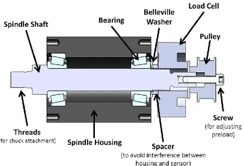
16 Chapter 1: Introduction A key component of the 2.72 lathe is the spindle, which must be carefully designed and calibrated in order for the lathe to work at peak performance. Figure 1.2 shows the parts contained in a typical 2.72 spindle.
Figure 1.2: Components of spindle. Though is some variation among individual spindle designs,
the components shown above are contained in every functional spindle design.
In addition to the housing, plate, chuck, and shaft, each spindle includes two bearings and hardware for preloading the bearings. Though students may choose any bearing set for their spindle design, many students select Timken LM11949/LM11910 bearings, the type shown in Figure 1.2. These bearings are typically preloaded by tightening the preload nut against the Belleville washer, applying an axial force to the bearing set.
As part of the lathe optimization process, 2.72 students are required to characterize the performance of their lathe spindle and select the optimal bearing preload level. Currently, the process for obtaining this data is inconvenient and time-consuming for both students and course staff. For example, in order to measure spindle error motion, students must make in advance a two-hour appointment with a staff member, who will walk them through the process of calibrating capacitance probes and obtaining data [1]. This arrangement is not scalable for larger class sizes and, with 2.72 enrollment numbers growing every semester, this is a problem. Experimental setups for measuring other performance data are left to the students to design, a practice which detracts valuable time from the project itself and often does not return useful results. An apparatus allowing students to acquire spindle performance data in the normal 2.72 lab space and unassisted by course staff would not only streamline the course, but allow
1.3 Bearing Preload
Preloads may be intentionally induced in a device by forcing two or more machine elements together and clamping them in such a way that the tension in some parts of the assembly balances the compression in other parts. The results of preloading are stresses within the assembled device without the application of external loads [2].
High-precision dynamic systems, such as lathes, require high stiffness levels and low deflection levels. They also usually involve bearings found in series with other machine elements, such as shafts or support structures. Because the deflection under load of rolling element bearings, such as those typically used in 2.72 spindle designs, are predominantly
governed by Hertz contact behavior, the typical force-displacement curves for such bearings are nonlinear. As shown in Figure 1.3, bearings typically behave as soft springs under light loads and stiff springs under heavy loads [2].
If bearings are soft springs in comparison with other elements in a device, they will dominate the combined spring rate and significantly lower the overall system stiffness. For this reason, it is common practice to preload bearings; that is, to tighten two bearings against each other in order to apply an initial, internal load to the bearings and effectively eliminate the softer, lower branch of the curve shown in Figure 1.3 [2].
Figure 1.3: Effect of preload on bearing stiffness. The graph shows how much axial load is
required to achieve a given bearing displacement. Note that the approximate stiffness, kpreload, of a preloaded bearing is higher than when the soft branch is included and that the stiffness of a preloaded bearing can be approximated as linear [2].
18 Chapter 1: Introduction In addition to increasing spindle stiffness, preloading a spindle will also decrease the radial error motion of that spindle. Radial error motion comes about because small spaces exist between the outer races of a bearing and the internal rolling elements which allow for endplay. Preloading increases stiffness precisely because it forces the inner and outer races of a bearing together. Therefore, as the contact area between bearing races and internal rolling elements increases, the potential for endplay that results in radial error motion decreases [3]. However, increasing the contact area in a bearing also results in an increase of contact forces between the inner and outer bearing races. This has the effect of increasing rotational friction and running torque in a spindle [2].
The trade-offs among increased stiffness, decreased error motion, and increased running torque are heavily dependent on the components and configuration of a given spindle [3]. Though an estimate of the optimal preload for a given spindle design may be obtained through modeling and calculation, it is difficult to obtain a fully accurate model of a complex mechanical system [2]. Therefore, the ideal situation is that the optimal preload for a given spindle be experimentally determined [3].
1.4 Overview of Design Approach
The measurement goals outlined in Section 1.3 require an apparatus that will measure four quantities: preload, radial stiffness, radial error motion, and running torque. The following three chapters will detail the approach used to design the necessary measurement apparatus, while the two final chapters evaluates the results of this design.
Chapter 2 outlines the design requirements for the apparatus.
Chapter 3 examines the design of the four measurement subsystems – one subsystem
for each quantity to be measured. This chapter will detail the selection of a measurement method for each quantity and the selection of the appropriate sensors. It will also discuss the additional design constraints imposed on the overall apparatus by each measurement
subsystem.
Chapter 4 will explain how the four measurement subsystems are integrated into a
cohesive apparatus design. This chapter details the physical design of the overall apparatus, as well as the configuration and procedure used for obtaining each measurement. This chapter also examines how the apparatus design meets the design requirements set forth in Chapter 2.
Chapter 5 provides an overview of the fabrication and assembly of the apparatus
components and structure.
Chapter 6 summarizes the work that was completed on this apparatus and explains
Chapter 2: Design Requirements
Design requirements for the apparatus are shown in Table 2.1; the sections following provide a more detailed explanation of each requirement category.
TABLE 2.1: Apparatus Design Requirements. Top-level design requirements for the apparatus
are shown in left column; the right column breaks them down into more detailed sub-requirements.
Requirements
Sub-Requirements
1 Acquire spindle performance dataA Measure bearing preload
B For various preload values, measure: (1) radial stiffness of spindle,
(2) run-out error of spindle, and (3) running torque of spindle
2
Be compatible with existing
2.72 spindle design
A Interface with spindle having standard 2.72 dimensions
B Require minimal modifications to existing 2.72 designs
C Not damage students spindles
3
Require minimal instructor assistance
A Allow students to attach their own spindle to apparatus
B Have simple, user-friendly operation
C Acquire data in a format that allows students to perform computer
analysis outside of lab
4
Be usable in a 2.72 lab environment
A Use inputs available in lab (e.g. 120 V AC power, pressurized air at
80 psi)
B Occupy minimal space on lab workbench
C Be easily moved and stored when not in use
5
Use existing 2.72 sensor
resources
A Use rotary torque sensor already owned by 2.72 to measure
running torque
B Allow easy removal of rotary torque sensor from apparatus for use
in other class exercises
C Use load cell already owned by 2.72 to measure preload
2.1 Acquire spindle performance data
In order to optimize their spindle performance with respect to preload, students must be able to use the apparatus to generate three curves: one showing the radial stiffness of the spindle vs. bearing preload, another showing radial error motion vs. bearing preload, and a third showing the running torque of the spindle vs. bearing preload. Therefore, the apparatus must first be capable of measuring bearing preload. Then, for a given preload value, the apparatus must be able to measure radial stiffness, radial error motion, and running torque.
20 Chapter 2: Design Requirements
2.2 Be compatible with existing 2.72 spindle design
Because students will use the apparatus to determine the ideal preload value for their actual spindle, it is crucial that the apparatus be capable of interfacing with spindles of a
standard 2.72 design. The critical dimensions of a standard 2.72 spindle are shown in Figure 2.1.
Figure 2.1: Critical dimensions of a typical 2.72 lathe spindle. The measurement apparatus
must be designed to interface with a spindle having the dimensions shown. Dimensions are given in inches.
Since students will be using the same spindle used for testing in their final lathe design, the spindle must not be damaged, either during installation or during the testing procedures. While small alterations to the standard 2.72 spindle design are acceptable, it is necessary that the changes be minimal and that they do not interfere with spindle performance.
2.3 Require minimal instructor assistance
In order to accomplish the goal of minimal instructor assistance, the apparatus must allow for students to install their spindles unassisted. The operation of the apparatus should be simple enough that a student can use it without direct supervision; ideally, operation of the apparatus would be simple enough to be explained during a group presentation (i.e. at the beginning of a lab session) or learned by reading instructional material available on the course website.
Once the desired data is acquired, students must be able to access and analyze the data outside of lab space. Therefore, the apparatus design must save acquired data in a format that is compatible with an analysis program accessible to MIT students (e.g. Matlab, LabVIEW, Excel).
2.4 Be usable in a 2.72 laboratory environment
The apparatus will be used by students in an MIT laboratory space, likely the MIT Laboratory for Manufacturing and Productivity (LMP) machine shop or the MIT Precision Compliant Systems lab. Therefore, any inputs to the apparatus must be readily available in either lab space. Available inputs are: 120 V AC (standard outlet) power and pressurized air at 80 psi.
Additionally, because the apparatus will be located in a student workspace where bench top space is limited, it is desirable for the apparatus to be as small and unobtrusive as possible. Since the apparatus will only be in use for a few weeks each term, it must be small enough to be stored in an MIT office or lab and light enough to be transported without excessive effort.
2.5 Use existing 2.72 sensor resources
2.72 already possesses a rotary torque sensor (discussed in more detail in Section 3.4.2), which will be used to measure running torque in the apparatus. However, the sensor is used for other class exercises throughout the term; as such, it is necessary that the torque sensor be easily attached to or removed from the final apparatus. The course also owns a through-hole load cell (discussed in Section 3.1.2) which will be used to measure preload.
Chapter 3: Subsystem Design
3.1 Measurement of Bearing Preload
3.1.1 Design Requirements for Preload Subsystem
The relevant design requirements for the bearing preload subsystem are:
1. The preload level must be readily adjustable (Requirement 1.B). Therefore, the load cell must be able to slide along the spindle shaft as preload is adjusted.
2. A given preload level must be maintained while radial error motion and running torque are measured (Requirement 1.B). Therefore, the spindle shaft must be free to rotate and the spindle shaft must be capable of interfacing a motor
3. The apparatus must accommodate a typical 2.72 spindle design, as described in Section 2.2 (Requirement 2).
4. Preload data must be communicated to a computer (Requirement 3.C).
5. The preload measurement must be obtained using the Omega LC8250 load cell already owned by 2.72, as described in Section 3.1.2 (Requirement 5.C).
3.1.2 Load Cell Sensor
An Omega LC8250-750-10K load cell, shown in Figure 3.1, is already in the possession of 2.72. This load cell will be used to obtain preload values in the measurement apparatus.
Figure 3.1: Load Cell. The apparatus uses the Omega LC8250 load cell to measure bearing
preload. The sensor has a through-hole to accommodate a shaft and measures loads axially. The critical dimensions of the load cell are shown in Figure 3.2. The sensor requires an input of 10-15 Vdc and has a measurement capacity of 0-10,000 lbs. [4].
Figure 3.2: Critical Dimensions of Load Cell. The critical dimensions for designing a
measurement setup with the Omega LC8250 load cell are shown. Dimensions are given in inches.
3.1.3 Sensor-Spindle Adapter Design
In order to use the Omega load cell to measure preload levels on existing 2.72 spindles, an adapter setup is needed. A screw-adjustable adapter design was selected, as such a design accommodates the dimensions of the existing load cell and requires minimal modification to the preexisting 2.72 spindle design.
A cross-section of the final adapter design is shown in Figure 3.3. The user may adjust the preload by turning the ¼ - 20 screw at the end of the adapter. Tightening the screw increases the clamping force against the pulley, load cell, spacer, and Belleville washer – all of which are able to slide axially along the spindle shaft. Therefore, by tightening the screw, the user will increase the clamping force against the outermost bearing race and preload the bearing.
Figure 3.3: Cross-section of sensor-spindle adapter. The adapter accommodates the Omega
load cell and typical spindle dimensions and allows a user to easily adjust bearing preload level by turning a screw.
Because none of the sliding elements are attached to the shaft, the shaft is still free to rotate. However, if the user desires to drive the spindle with a motor, the pulley may be constrained to rotate with the shaft by tightening a set-screw. The pulley, and therefore the spindle, can then be connected to a motor with a belt. Including a pulley in this setup allows for the spindle to be driven by a motor without inhibiting access to the adjustment screw on the end of adapter; even when a belt is attached between the pulley and a motor, it is still possible to adjust the preload value by tightening the screw.
In order to use this adapter setup, a few changes must be to the standard 2.72 lathe spindle. Students will need to drill and tap a ¼ -20 hole with 0.5" depth in the end of their spindle shafts for the purpose of engaging the preload adjustment screw. This, however, is a minor change that will not affect the overall performance of the lathe assembly. It will also be necessary to temporarily remove the plate from the back of the spindle while measurements are taken; otherwise, the plate might constrain the axial motion of the load cell so that it cannot make contact with the bearing.
3.1.4 Constraints Imposed by Preload Subsystem
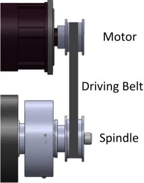
Three design constraints are imposed on the apparatus by the preload sensor setup: 1. In order to drive the spindle from the back, a driving motor must be configured for a
belt-drive system, with a pulley that is vertically aligned with the spindle pulley, as shown in Figure 3.4.
Figure 3.4: Vertical Alignment Constraint. A motor driving the spindle from the back must be
placed so as to align its pulley with the pulley on the adapter.
Motor
Spindle
Driving Belt
2. Users must have ready access to the preload adjustment screw at the back of the spindle.
3. The load cell requires a power source with an output between 10-15 Vdc and a data output line.
3.2 Measuring Radial Stiffness
3.2.1 Design Requirements for Radial Stiffness Subsystem
The relevant design requirements for the radial stiffness subsystem are: 1. In order to measure spindle stiffness, the spindle must be radially deflected a
measureable amount (3-10 µm) under a known load, as illustrated in Figure 3.5 (Requirement 1.B).
Figure 3.5: Loading requirements for spindle stiffness test. The apparatus must be able to
apply a radial load to the end of the spindle shaft in order to most closely simulate the load applied by a cutting tool.
2. The apparatus must accommodate a typical 2.72 spindle design, as described in Section 2.2 (Requirement 2).
3. Load and displacement data must be communicated to a computer (Requirement 3.C). 4. The deflection load must be applied by a small, manageable load application tool
(Requirement 4).
3.2.2 Load Application Device
Several different methods for load application were considered for this device.
However, before selecting the most appropriate method, it was necessary to estimate the force required to deflect a typical 2.72 spindle 10 µm.
In a typical 2.72 spindle, two elements contribute to the stiffness of the spindle: the spindle shaft and the bearings. The contribution to stiffness by the spindle shaft can be
30 Chapter 3: Subsystem Design determined by modeling the shaft as a steel rod suspended between rigid supports, as shown in Figure A.1. The contribution of the bearings can be determined by modeling them as springs supporting a rigid beam, as shown in Figure A.2. [2]. Then, using basic beam theory, the stiffness of the flexible shaft is determined to be
3
3
l EI
kshaft . (A.9)
(see Appendix A). The stiffness due to bearing flexibility can be similarly determined using geometry and the constitutive relationships governing springs (see Appendix A). It is given by the equation 1 2 1 2 2 L l L l k kbearings . (A.19)
Combining these two stiffness equations using superposition and substituting the appropriate numerical values gives an overall stiffness of
in lbf x
kspindle 5.8475 105 for the spindle. Therefore, in order to deflect the non-preloaded spindle system 10 µm, a radial force of approximately 230 lbf must be applied. To account for the greater stiffness resulting from preloading, we will seek a load application device that can apply loads in the 250-500 lbf range (see Appendix A).
Given this guideline, a Pugh chart comparing the considered load application methods can be found in Table 3.1. For each category, a device capable of achieving the necessary load was considered when making the comparisons.
TABLE 3.1: Pugh chart comparing load application methods. Though a set of weights allows for
the greatest control and an electronic actuator is the easiest to use, an air cylinder is comparatively small and light, relatively easy to use, and can be controlled indirectly by adjusting input air pressure.
Load Application
Method
Size Weight Ease of Use Use of inputs available in shop Ability to control applied load Ability to measure applied load Total Air Cylinder 0 0 0 0 0 0 0 Set of Weights -1 -1 -1 0 1 1 -1 Electronic Actuator -1 -1 1 0 0 -1 -2 Pneumatic Cylinder 0 -1 0 -1 -1 -1 -4
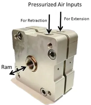
In light of its small size and weight, its relative ease of use, and the ability to control and measure its applied load, an air cylinder was selected as the load application device that best suited the needs of this apparatus. In order to meet the loading capability requirements as determined above, a pancake air cylinder, as shown in Figure 3.6, was selected.
Figure 3.6: Pancake air cylinder. This pancake air cylinder is used in the apparatus to apply a
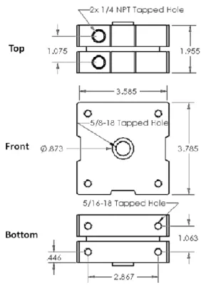
load during stiffness tests. It is controlled by adjusting the air pressure at the input valves. The critical dimensions of this air cylinder are shown in Figure 3.7. It has a ¼” stroke length, more than sufficient for the 3-10 µm displacement requirement, and a 646 lb. load capacity at 100 psi driving pressure (which translates to approximately 517 lb. load capacity at the shop air pressure of 80 psi). It is dual-acting, so the ram can apply a load in either direction (by extending or retracting its ram). The direction of the stroke can be changed by switching the air supply between two available input ports and the output load of the air cylinder can be varied by changing the air pressure at the input [5].
32 Chapter 3: Subsystem Design
Figure 3.7: Critical Dimensions of Air Cylinder. The critical dimensions for designing a
measurement setup with the pancake air cylinder are shown. Dimensions are given in inches.
3.2.3 Digital Indicator
In order to measure displacement at the required resolution, an upgrade to the digital indicator already owned by 2.72 was required. The Mitutoyo ID-S112TB digital indicator, shown in Figure 3.8, was selected.
Figure 3.8: Digital Indicator. The Mitutoyo ID-S112TB digital indicator is used in the apparatus
to measure shaft displacement during stiffness testing. The stylus is placed in contact with the spindle and retracts or extends to measure displacement.
Retractable
Stylus
Computer
output cable
connection
This digital indicator has an accuracy of ±0.00012" and is therefore capable of detecting displacements of 3 µm or greater. It is battery-powered, so it does not require an external power source, and it connects to the computer via an SPC data cable [6]. The critical dimensions of the digital indicator are shown in Figure 3.9.
Figure 3.9: Critical dimensions of digital indicator. The critical dimensions for designing a
measurement setup with the Mitutoyo ID-S112TB digital indicator are shown. Dimensions are given in inches.
3.2.4 Radial Stiffness Subsystem Design
In order to apply a load, the ram of the air cylinder must be connected with the lathe spindle. This could be accomplished in two ways: either by having the ram directly contact the spindle, displacing the end of the spindle outwards as the ram extends; or by connecting the ram to the spindle with a cord so that it pulls the spindle towards itself as it retracts. However, to avoid damaging the spindle shaft by directly contacting it with the ram, the load will be applied by retracting the ram. The ram will be attached to the spindle with fishing line, as shown in Figure 3.10. This attachment provides for the safety of the user: if the fishing line were to fail, it would simply break and its fragments would not cause serious injury.
34 Chapter 3: Subsystem Design
Figure 3.10: Configuration of the radial stiffness subsystem. In order to measure radial
stiffness effectively, the air cylinder ram and digital indicator stylus must be axially aligned. The air cylinder will be attached to the spindle with fishing line.
The digital indicator stylus must be placed in parallel with the air cylinder rod and connecting line. In order to avoid damage to the digital indicator in the case of fishing line failure, the digital indicator will be placed opposite the air cylinder, as shown in Figure 3.10. It will be oriented so that the stylus is partially retracted and set to measure stylus extension as positive displacement.
In order to determine spindle stiffness for a given preload level, measurements of spindle displacement for several different applied loads must be obtained. As mentioned in Section 3.2.2, the force applied by the air cylinder can be controlled by adjusting the pressure of air at the air cylinder input. The input for the air cylinder will be provided using pressurized air lines in a student shop; therefore, the input pressure will need to be changed by adjusting the pressure at the line source. The user will monitor input pressure to the air cylinder using a pressure gauge and manually record the pressure value for each trial. Finally, he will convert the recorded pressures to applied force values by using a calibration curve.
As mentioned above, the direction of the air cylinder ram is determined by changing the input port to which pressurized air is applied. The extension and retraction of the rod will be controlled by opening and closing manual valves, as illustrated in Figure 3.11.
Figure 3.11: Control of air cylinder ram direction. By opening and closing manual valves, the
user will control the direction in which the ram moves. To extend the ram, the right (retract) valve must be closed and the left (extend) valve closed; the opposite is true to retract the ram. When both valves are closed, the ram does not move.
No external power supply is necessary for this setup, though the digital indicator does require a data output.
3.2.5 Constraints Imposed by Radial Stiffness Subsystem
The following design constraints are imposed by the radial stiffness subsystem:
1. The digital indicator, spindle shaft, and air cylinder rod must be aligned and connected as shown in Figure 3.10.
2. There cannot be any obstructions between the air cylinder and the spindle shaft at the time the load is applied.
3. The digital indicator requires a data output line.
4. The air cylinder requires a pressurized air line as an input.
3.3 Measurement Setup for Radial Error Motion
3.3.1 Design Requirements for Radial Error Motion Subsystem
The relevant design requirements for the radial error motion subsystem are: 1. In order to effectively measure radial error motion, the spindle must be capable of
rotating (Requirement 1.B).
2. The apparatus must accommodate a typical 2.72 spindle design, as described in Section 2.2 (Requirement 2).
36 Chapter 3: Subsystem Design 3. Radial error motion data must be communicated to a computer (Requirement 3.C).
3.3.2 Donaldson Ball Reversal
The Donaldson Ball Reversal technique is the rotational equivalent of the well-known straightedge reversal technique; it is used to separate the radial error motion of a spindle from the roundness profile of the spindle shaft. The technique accomplishes this by taking two measurements [7].
The first measurement is taken from the position shown in figure 3.12(a); as the spindle is rotated 360°, a digital indicator registers the variations of the surface from a perfect circle. The curve, M1(θ), that is a recorded during the first test is given by
) ( ) ( ) ( 1 P S M , (3.1)
where P(θ) is the roundness profile of the spindle shaft and S(θ) is the radial error motion of the spindle [8].
Figure 3.12: Schematic of Donaldson Reversal Technique: (a) shows the original orientation of
the measurement instrument (indicated by an arrow) and the spindle shaft. (b) shows the reversed orientation of the same components [7].
The second measurement is taken from the position shown in Figure 3.12(b), with both the spindle and the indicator located 180° opposite their original positions. This effectively reverses the recorded radial error motion, so that the curve, M2(θ), that is recorded during the
second test is given by
) ( ) ( ) ( 2 P S M . (3.2)
Once both curves have been recorded, it is a simple matter to calculate the radial error motion by using the following equation
2 ) ( ) ( ) ( M1 M2 S (3.3) [8].
In order to use this tactic for measuring radial error motion, it is necessary to have a means for rotating the spindle exactly 180° and 360°. This rotation can be done by hand using a
rotational guide or, more accurately, by controlling a motor to rotate the desired amount. It is also necessary to be able to measure displacement with a resolution of at least 3 µm from two positions 180° apart around the spindle. This can be done with a digital indicator, mounted in two different positions, as shown in Figure 3.13.
Figure 3.13: Digital indicator placement. To effectively measure radial error motion, the digital
indicator is used in a different location for the original location and its reversal. The two positions must be separated by 180° with respect to the spindle axis.
3.3.3 Component Selection
There are two necessary components for a reversal test: a digital indicator, to measure edge variation as discussed in Section 3.3.2, and a motor to provide rotation during the test. The digital indicator selected for use in the radial stiffness test has sufficient resolution for use in the reversal test; the specifications of this model are discussed in detail in Section 3.2.3.
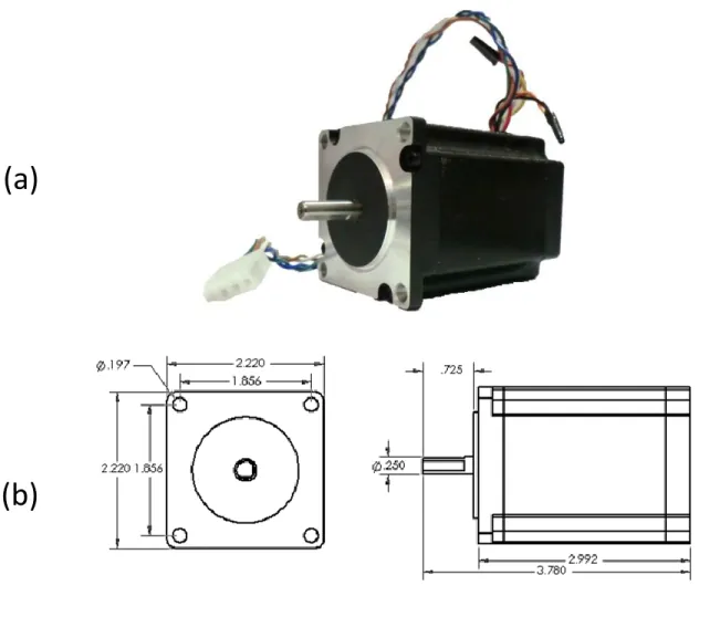
Because a high degree of rotational accuracy is required for a successful reversal test, a Keling KL23H276-30-8B stepper motor was selected to provide rotation. This is an open-loop motor, so it provides rotational accuracy without requiring any external feedback. The Keling motor, with relevant dimensions, is shown in Figure 3.14.
38 Chapter 3: Subsystem Design
Figure 3.14: Stepper Motor, with critical dimensions. (a) A Keling stepper motor will be used in
the apparatus to provide rotation during radial error motion measurements. (b) The critical dimensions for Keling motor are shown. Dimensions are given in inches [9].
Using an Arduino microcontroller and a RepRap Stepper Motor Driver 2.3, this motor is configured so that students can push a button on the Arduino and cause the motor to rotate exactly 360° and then back 180° (see Appendix B).
3.3.4 Constraints Imposed by Radial Error Motion Subsystem
The following constraints are imposed by the radial error motion subsystem:
1. The stepper motor must connect to the spindle, without slipping, in order to drive it. 2. In order to maintain clear access to the front of the spindle, the stepper motor must
drive the spindle from the back.
3. The digital indicator must be movable to two positions, 180° apart with respect to the spindle, as shown in Figure 3.13.
4. In both positions, the stylus of the digital indicator must be in contact with a circular cross-section of the spindle.
(a)
5. The stepper motor requires a power input of 12 Vdc.
3.4 Measurement of Running Torque
3.4.1 Design Requirements for Running Torque Subsystem
The relevant design requirements for the running torque subsystem are:
1. In order to effectively measure running torque, measurements must be taken while the spindle is undergoing continuous rotation (Requirement 1.B).
2. The speed of spindle rotation must be controllable within the typical speed range for 2.72 lathes, between 800-2000 rpm, while measurements are taking place (Requirement 1.B).
3. The apparatus must accommodate a typical 2.72 spindle design, as described in Section 2.2 (Requirement 2).
4. Torque and speed data must be communicated to a computer (Requirement 3.C). 5. The running torque measurement must be taken with a FUTEK TRS605 rotary torque
sensor, as described in Section 4.3.2 (Requirement 5.A).
3.4.2 Rotary Torque Sensor
A FUTEK FSH02057 rotary torque sensor was already in the possession of 2.72 and was therefore used to measure running torque in this apparatus. The sensor has both an input and an output port, as shown in Figure 3.15.
Figure 3.15: FUTEK Rotary Torque Sensor. A FUTEK FSH02057 rotary torque sensor will be used
in the apparatus to measure running torque. The sensor must be axially aligned with and physically connected to a motor and the spindle in order to measure effectively.
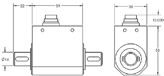
Because it uses strain gauges to measure the difference in angle between the input and output shafts, this sensor is designed to be used in series with the load (in this case, the spindle) and the driver (a motor) [10]. The critical dimensions of the torque sensor are shown in Figure 3.16.
Figure 3.16: Critical dimensions of rotary torque sensor. The critical dimensions for designing a
measurement setup with the FUTEK torque sensor are shown. Dimensions are given in centimeters [11].
The rotary torque sensor requires an input of 11-26 Vdc and has a measurement capacity of 0-443 in-lbs (0-50 N-m) [12].
3.4.3 Continuous Rotation Motor
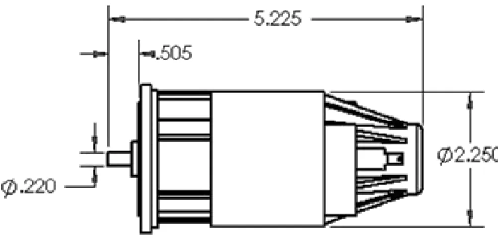
In order to most closely simulate the operating conditions of 2.72 lathe, a DeWalt BP-389010-00 hammerdrill motor (the same motor typically used in 2.72 lathe designs) was selected to drive the spindle while measuring running torque. This motor is pictured in Figure 3.17.
Figure 3.17: Continuous rotation motor. A DeWalt hammerdrill motor – the same motor used
in typical 2.72 lathes – will be used in the apparatus to provide rotation during running torque measurements.
Though the same stepper motor selected to drive the motor during radial error motion measurements could be used while measuring running torque, it is easier to control the speed of a continuous-rotation motor. The critical dimensions of the motor are shown in Figure 3.18.
Input Voltage
(from power supply)
+
_
Output
Figure 3.18: Critical dimensions of continuous rotation motor. The critical dimensions for
designing a measurement setup with the DeWalt BP-389010-00 hammerdrill motor are shown. Dimensions are given in inches.
The speed of this motor is dependent upon the input voltage; thus, if the motor is powered by a variable power supply, students can easily control the motor speed while measuring the running torque. The speed is measured by an encoder build into the FUTEK sensor and recorded on the computer.
3.4.4 Running Torque Subsystem Design
The overall design for this measurement setup is simple: the three components (motor, rotary torque sensor, and spindle) must be axially aligned and coupled. All three components must be clamped in place in order to minimize rattling; therefore, in order to avoid
over-constraining the assembly, flexible shaft-couplings are be used to allow for slight misalignments between components. These two constraints lead to the subsystem design shown in Figure 3.19.
Figure 3.19: Configuration of running torque subsystem. To measure running torque
effectively, the motor, torque sensor, and spindle must be axially aligned and connected by flexible couplings to avoid over-constraining the assembly.
44 Chapter 3: Subsystem Design This measurement setup also requires two power sources: a variable one for the motor, which will be provided by a variable DC power supply, and a constant one for the rotary torque sensor.
3.4.5 Constraints Imposed by Running Torque Subsystem
Three design constraints are imposed by the running torque subsystem:
1. The motor, rotary torque sensor, and spindle must be aligned and spaced as shown in Figure 3.19.
2. The rotary torque sensor requires a 12 Vdc power source and data output line. 3. The motor requires a separate, variable power source.
Chapter 4: System Integration
4.1 Reconciling Subsystem Constraints
Each measurement setup imposes some additional design constraints which must be reconciled with one another in order to build a complete apparatus. Table 4.1 details conflicts between constraints and how those conflicts are resolved in the integrated system.
TABLE 4.1: Reconciling design constraints. Some of the measurement subsystems have
constraints that pose a potential conflict; the left column details each potential constraint conflict, while the right column explains how the constraints might be reconciled.
Conflict Solution
The stepper motor must drive the spindle from the back, without slipping; any motor connection at the back of the spindle must be made using a pulley, in order to maintain
access to the preload adjustment screw.
A timing-belt pulley system will be used to connect the stepper motor and the spindle, in
order to avoid slipping between the pulleys and the belt.
The rotary torque sensor must be located in-line with and between the driver and the spindle, but the stepper motor
must drive the spindle from the back via a pulley system.
The rotary torque sensor will connect to the spindle from the front and be driven by a
separate motor. It is more convenient to use a standard motor during running
torque measurement, but a stepper motor is necessary during the reversal tests.
Two separate motors will be used, as determined above.
There must be clear access to the front of the spindle during stiffness testing, but the rotary torque sensor must be in
contact with the front of the spindle.
The rotary torque sensor and its driving motor will be located on a sliding platform, in order
to remove it from contact with the spindle during other measurements. The stepper motor can be easily disconnected by removing
the timing belt. It is necessary that the digital indicator be in contact with the
spindle shaft during stiffness and radial error testing, but it cannot be in contact with the shaft during running torque
measurement.
The single digital indicator can be moved between two locations, 180° apart, or it can be
removed entirely.
There are also multiple sensors which require a power supply and a data output line. An ATX power supply, which plugs into a standard wall outlet and is capable of providing +3.3 Vdc, +5 Vdc, and ±12 Vdc, will satisfy all of the apparatus power requirements, with the exception of the variable power supply needed for the continuous rotation motor. The ATX power supply is shown in Figure 4.1.
Figure 4.1: ATX Power Supply. All of the power requirements for the apparatus will be satisfied
by the ATX power supply.
All of the sensors will interface with an Arduino microcontroller, which saves the information to an SD card using an appropriate Arduino shield (see Section 7.2.1.)
4.2 System Overview
For reference, Figure 4.2 shows the important features of the apparatus.
Figure 4.2: Complete measurement apparatus. The complete apparatus design is shown above,
4.2.1 Spindle Installation
In order to use this apparatus for measurement, the user must first install a spindle of his own design into the apparatus. Figure 4.3 shows a schematic of this process.
Figure 4.3: Spindle Installation Process. (a) The preload nut and plate are removed from the
spindle so that (b) the load cell adapter can be installed on the back of the spindle. Then, (c) the spindle is installed into the front support of the apparatus and secured with four ¼ - 20 screws. Finally, (d) the stepper motor is installed by sliding the stepper motor clamp over the spindle and tightening a screw to secure the clamp.
(a)
(b)
(c)
4.2.2 Procedure for Measuring Stiffness vs. Preload
While measuring the radial spindle stiffness, the apparatus should be configured as shown in Figure 4.4.
Figure 4.4: Apparatus configuration while testing radial stiffness. The user must (a) install the
digital indicator by placing the magnetic back of the indicator holder against a steel disc and pushing the edges of the holder against three alignment pins. Then, (b) the user must connect the air cylinder to the spindle using fishing line and provide a pressurized air line for the cylinder.
(a)
(b)
Pressurized
Air Inputs
Alignment Pin
Steel disc
Indicator
Holder
The first preload measurement is taken by tightening the preload screw and acquiring a reading from the load cell on the computer, as shown in Figure 4.5.
Figure 4.5: Measuring bearing preload level. By tightening the preload adjustment screw, the
user can change the bearing preload level. The preload level is measured by the load cell, which receives power and outputs data through the I/O cable shown.
After recording the preload level, a measurement for the radial stiffness corresponding to that preload level is acquired by taking the following steps:
1. The air input valve that controls extension is opened until the ram is fully extended. The valve is then closed.
2. An input air pressure for the air cylinder is set using the pressure regulator. This input pressure is recorded.
3. The digital indicator is zeroed and placed in “acquire” mode.
4. The air input valve that controls retraction is opened until the ram is fully extended. The valve is then closed.
5. The digital indicator is placed in “standby” mode.
6. Steps 1-5 are repeated for as many input pressures as desired. Each repetition provides one data point for a force vs. displacement graph, which can be used to find spindle stiffness at a given preload level.
The preload level is then adjusted and these measurement procedures repeated in order to obtain additional data points. The data points can later be plotted to obtain a graph of stiffness vs. preload. Once all desired stiffness measurements have been completed, the fishing line connecting the air cylinder to the spindle should be removed and the supply of pressurized air disconnected.
4.2.3 Procedure for Measuring Radial Error Motion vs. Preload
While measuring radial error motion, the apparatus should be configured as shown in Figure 4.6(a), with the digital indicator installed and a timing belt connecting the two pulleys.
Figure 4.6: Apparatus configuration while measuring radial error motion. (a) During the first
rotational measurement, the digital indicator is located as it was during the measurement of radial stiffness. (b) It is then rotated 180° about the spindle axis for the second rotational measurement.
First, a preload measurement is taken by following the procedure illustrated in Figure 4.5. The load cell I/O cable is unplugged, the cable secured against the sensor, and the pulley set screw tightened. The pulleys are 1/8” wider than the timing belt, so sliding the spindle pulley axially as the preload level is changed will not result in a pulley system misalignment.
A reversal test may now be run. To do this, the apparatus should be configured as shown in Figure 4.6(a) and the digital indicator zeroed and placed in “acquire” mode. Then, the Arduino reset button is hit to activate the stepper motor (see Appendix B). After the motor has rotated the shaft 360°, the digital indicator is placed in “standby” mode. The reversal test is
then completed by moving the digital indicator as shown in Figure 4.6(b) and repeating the measurement procedure.
After reversal test data has been acquired, the pulley set-screw is disengaged, the load cell reattached to the computer, and the process repeated. This process may be repeated to obtain as many data points as desired for a radial error motion vs. preload graph.
4.2.4 Procedure for Running Torque vs. Preload
While measuring running torque, the apparatus should be configured as in Figure 4.7.
Figure 4.7: Apparatus configuration while measuring running torque. To configure the
apparatus for measuring running torque, (a) the user moves the sliding base forward and (b) secures it to the apparatus base with four ¼ - 20 screws. The final configuration is shown in (c).
To begin, a preload measurement is taken following the procedure illustrated in Figure 4.5; then, the load cell I/O cable is disconnected. Running torque data can now be obtained for the set preload value. This is done by adjusting the voltage supply to the hammerdrill motor while the rotary torque sensor is set to acquire torque and speed data.
Once running torque data has been acquired, the load cell is reattached to the computer and the process is repeated. The process may be repeated to obtain as many data points as desired for a running torque vs. preload graph.
4.3 Meeting Design Requirements
Table 4.2 provides an overview of how the system meets the design requirements.
TABLE 4.2: Fulfillment of design requirements. The left column of this table reviews the design
requirements laid out in Section 2.1; the right column explains how each requirement was met in the apparatus design.
Requirements Sub-Requirements Evaluation
1
Acquire spindle performance
data
A Measure bearing preload Met; see Sections 5.2.2 through 5.2.4
B
For various preload values, measure: (1) radial stiffness of spindle, (2)
run-out error of spindle, and (3) running torque of spindle
Met; see Sections 5.2.2 through 5.2.4
2
Be compatible with existing 2.72 spindle
design
A Interface with spindle having
standard 2.72 dimensions Met; see Section 5.2.1
B Require minimal modifications to
existing 2.72 designs
The only necessary modification is a 0.5” ¼ - 20 hole drilled in the end of the spindle (see
Section 3.1.3.)
C Not damage students spindles Met; see Section 5.2
3
Require minimal instructor assistance
A Allow students to attach their own
spindle to apparatus Met; see Section 5.2.1
B Have simple, user-friendly operation
The data acquisition process could be completely explained to students in a
document (See Section 5.2).
C
Acquire data in a format that allows students to perform computer
analysis outside of lab
Data is acquired and stored on an SD card, which can then be read on a student computer and the data analyzed with their
software of choice.
4
Be usable in a 2.72 lab environment
A Use inputs available in lab (e.g. 120 V
AC power, pressurized air at 80 psi)
Required power sources are 120 V AC power and pressurized air at 80 psi.
B Occupy minimal space on lab
workbench
The apparatus has dimensions of 12” x 16” x 5”. A variable DC power supply, 12 Vdc power supply, and an Arduino stack are also
required.
C Be easily moved and stored when
not in use The complete apparatus weighs 28 lbs.
5
Use existing 2.72 sensor resources
A
Use rotary torque sensor already owned by 2.72 to measure running
torque
Met; see Section 3.4.2.
B
Allow easy removal of rotary torque sensor from apparatus for use in
other class exercises
The rotary torque sensor can easily be removed by unscrewing one screw and sliding the sensor clear of the plastic clamp
that holds it in place (see Section 5.2.4.)
C Use load cell already owned by 2.72
Chapter 5: Fabrication and Assembly
5.1 Fabrication
5.1.1 Base Plate
The base plate of the apparatus was fabricated using a sheet of aluminum stock with 0.75” thickness. First, a 12” x 16” rectangle was cut out on a waterjet. As shown in Figure 5.1(a), a rectangular pocket, which allows the torque sensor assembly to slide back and forth, was cut on a CNC mill. Mounting holes for the front plate, air cylinder, and torque sensor assembly were also drilled using a mill. Finally, the mounting holes for front plate and air cylinder were
counterbored on a drill press, as shown in Figure 5.1(b), and the mounting holes for the torque sensor assembly were tapped.
Figure 5.1: Base Plate. (a) shows the top of the base plate, most of which was fabricated on the
mill; the counterbores shown in (b) were fabricated using a drill press.
5.1.2 Front Plate
The front plate of the apparatus was also fabricated using a sheet of aluminum stock with 0.75” thickness. The front plate outline, including the 1” hole in the center which allows the spindle shaft to pass through, was cut out from the stock using a waterjet. Then, as shown in Figure 5.2(a), a circular pocket for mounting the spindle housing was cut into the back of the
plate using a CNC mill. Mounting holes for the spindle housing were also drilled using a mill. Most features on the front of the plate, shown in Figure 5.2(b), were also fabricated on a mill, including the two circular pockets for mounting steel shim stock (to provide a magnetic surface for the digital indicator assembly) and holes for holding the digital indicator alignment pins. The counterbores for the spindle housing mounting holes were made using a drill press. Finally, the mounting holes on the bottom of the plate, shown in Figure 5.2(c), were drilled using a mill and tapped.
Figure 5.2: Front Plate. (a) The features on the back of the plate were fabricated using a mill.
(b) Most of the features on the front of the plate were also milled, though the counterbores were fabricated using a drill press. (c) The mounting holes on the bottom of the plate were drilled on a mill.
5.1.3 Torque Sensor Sliding Base
A base for the torque sensor assembly, capable of sliding along the rectangular pocket discussed in Section 5.1.1, was fabricated using a piece of ABS plastic stock with 1” thickness. First, the stock was cut to size on a bandsaw and squared on a mill. Eight through-holes were then drilled on a mill, as shown in Figure 5.3. Finally, using a drill press, the four holes to be used in mounting the sliding base to the base plate were counterbored on the top of the sliding base, as shown in Figure 5.3(a); the four holes to be used in mounting the sensor assembly to the sliding base were counterbored on the bottom, as shown Figure 5.3(b).
Figure 5.3: Torque Sensor Sliding Base. The base outline and the through holes were drilled
using a mill, while the counterbores (a) on the top face and (b) on the bottom face were fabricated using a drill press.
5.1.4 Mounting Clamps
Three clamps, all of similar design, were fabricated to hold the stepper motor, hammerdrill motor, and rotary torque sensor in place during operation. These clamps were fabricated using ABS plastic stock with 0.75” thickness. In each case, the stock was rough-cut into rectangles of the appropriate size on a bandsaw and squared using a mill. As shown in Figure 5.4, mounting holes were drilled and tapped in the bottom of two clamps using a mill.
Figure 5.4: Mounting holes on the bottom of clamps. Holes for mounting the clamps to the
The outline of the three clamps, including the interior pockets, were cut on a CNC mill; though a shallow cut was made as a guide, stock was left between the clamping ends of each piece to provide stability during further operations. Then, clamping holes were drilled through each clamping end using a mill and counterbored on the appropriate side on a drill press, as shown in Figure 5.5.
Figure 5.5: Intermediate steps in fabricating mounting clamps. The outline of each clamp was
cut on a mill, leaving some stock between the clamping ends. Then, clamping holes were drilled through each clamping end on a mill and couterbored on a drill press.
Finally, as shown in Figure 5.6, the stock remaining between clamping ends was
removed by using a bandsaw to cut along the guide grooves shown in Figure 5.5(a). The edges were smoothed with a file.
Figure 5.6: Mounting clamps. The mounting clamps were finished by removing the stock
5.1.5 Digital Indicator Holder
A holder for the digital indicator was fabricated using ABS stock of 1” thickness. The stock was cut to an appropriate size on a bandsaw and then squared using a mill. Then, as shown in Figure 5.7(a), a hole to fit the digital indicator stem was cut on the side of the stock using a CNC mill. Similarly, a pocket for a round magnet was cut on the back of the holder, as shown in Figure 5.7(b). Finally, a rectangular pocket (to allow space for the digital indicator body to rest) was cut in the top of the holder using a mill, as shown in Figure 5.7(c).
Figure 5.7: Digital indicator holder. (a) A hole on the side for the digital indicator stem, (b) a
pocket on the back to hold a magnet, and (c) a rectangular pocket on the front were all cut using a CNC mill.
5.1.6 Spindle Pulley
A special pulley was fabricated for use on the end of the spindle-load cell assembly. The pulley itself was ordered from McMaster-Carr (Part # 57105K18) and had a 0.25” bore to begin [13]. A vee-clamp was used to hold the pulley in place on a CNC mill while a pocket to
accommodate the shaft end, as shown in Figure 5.8, was cut on the mill.
Figure 5.8: Spindle pulley. A vee-clamp was used to hold the pulley in place as the non-circular
5.2 Assembly
5.2.1 Base Assembly
The base assembly provides the main support structure for all the measurement subsystems and contains the parts listed in Appendix C. First, two round pieces of steel shim stock were fixed into pockets on the front plate using Epoxy. Six spring pins were then pressed into holes on the front plate. Finally the front plate was screwed onto the base plate using four ¼ - 20 cap screws, as shown in Figure 5.9.
Figure 5.9: Base assembly. The components of the base assembly were put together using
epoxy, a press, and cap screws.
5.2.2 Spindle Assembly
The spindle assembly contains the user’s spindle, the load cell, and the load cell adapter and was constructed using the parts listed in Appendix C. First, two washers, the load cell, and a pulley were threaded onto the spindle shaft. These items were then secured in place by a ¼ - 20 cap screw. Finally, the spindle housing and the stepper motor were inserted into a plastic clamp and secured using two ¼ - 20 cap screws, as shown in Figure 5.10.