HAL Id: hal-00973434
https://hal.archives-ouvertes.fr/hal-00973434
Submitted on 23 Apr 2019
HAL is a multi-disciplinary open access
archive for the deposit and dissemination of
sci-entific research documents, whether they are
pub-lished or not. The documents may come from
teaching and research institutions in France or
abroad, or from public or private research centers.
L’archive ouverte pluridisciplinaire HAL, est
destinée au dépôt et à la diffusion de documents
scientifiques de niveau recherche, publiés ou non,
émanant des établissements d’enseignement et de
recherche français ou étrangers, des laboratoires
publics ou privés.
Concurrent control system: from Grafcet to VHDL
Frédéric Mallet, Daniel Gaffé, Fernand Boéri
To cite this version:
Frédéric Mallet, Daniel Gaffé, Fernand Boéri. Concurrent control system: from Grafcet to VHDL.
Euromicro 2000, Sep 2000, Maastricht, Netherlands. pp.230-234. �hal-00973434�
Concurrent Control Systems:
from Grafcet to VHDL
Fr´ed´eric Mallet, Daniel Gaff´e, Fernand Bo´eri
Laboratoire Informatique, Signaux, Syst`emes (I3S)
Universit´e de Nice Sophia Antipolis / CNRS
BP121, 06083 Sophia Antipolis cedex
email: [email protected], [email protected], [email protected]
Abstract
The Automated Production Systems (APS) are composed of concurrent interacting entities. Then any model should exhibit parallel and sequential behaviours. The Grafcet is now well established in manufacturing to specify the awaited behaviour of the APS. Moreover, programmable components increase modularity and allow a higher inte-gration rate of circuits. This paper intends to study the hardware implementation of a Grafcet specification into such a component. Those components has to be pro-grammed using an hardware description language. So we focus on inherent problems of such an approach and we study different kinds of possible solutions to automatically translate aGrafcet specification into aVHDL program. In
particular, we introduce a solution based on synchronous language works about symbolic research of stability states. This compiler only accepts the stable grafcets. In addition to automatically generate a VHDLcode, this solution pro-vides some way to check some safety properties onGrafcet.
Keywords : Specification, Modelling,GRAFCET,VHDL, programmable components,FPGA.
1. Interests and objectives
1.1. Grafcet
The Automated Production Systems (APS) are com-posed of concurrent interacting entities. Then any model should exhibit parallel and sequential behaviours. The
Grafcet is now well established in manufacturing to spec-ify the awaited behaviour of the APS. The model qualities explain this success. Grafcet owns these operators and gives them a nice graphical representation. It keeps parallelism of
the application. It tries to be as much as possible indepen-dent from technological and material aspects. Moreover the APS often integrate the characteristics of reactive real-time systems since all of them must react with determinism and in limited time.
InGrafcet, reactivity is expressed by the transition con-ditions (environment effect towards controller) and actions linked to step (controller effect towards environment). The model takes Petri nets away in spite of its historical link be-cause each firable transition must be fired (called cleared in
Grafcet) as soon as it becomes firable. The evolution rules give it some interesting deterministic features.
1.2. Implementation
Control systems are sequential and many people use logic hardware since thirty years. Nowadays we use pro-grammable components which have lots of good specific properties. In particular it allows a modular design of the hardware circuits, with a reasonable cost of components. Moreover the localisation of functionalities in a single chip makes easier repairing and duplication.
Until now the classical way to implement controllers de-signed in Grafcet is to use Programmable Logic Controller (PLC). In this article we intend to study the hardware im-plementation of Grafcet models using programmable com-ponents. This approach has also hold the attention of au-thors [10]. Obviously, our goal is not to replace PLC by a programmable component. We only think that the se-quential core of the PLC could be replaced by the specific programmable component designed in grafcet and to keep power input/output of the PLC.
The following chapter presents several problems raised by this approach. Then the chapter 3 shows different pos-sible solutions. We emphasize upon every good and bad aspects of different proposed methods. Finally, we advo-cate our preferred choice which allows some validations of
properties about the specification.
2. Translation problems from Grafcet to
VHDL
2.1. Grafcet
At the beginning, Grafcet was designed as a specifica-tion formalism for the control devices. Thus, the mod-elled command could be programmed (microprocessor, Programmable Logic Controller) or be wired with the most suitable technology (electric, hydraulic, pneumatic).
The expression power of Grafcet quickly lead industrials to develop on their own hardware a ’programming grafcet language’. None of these implementations has the same behaviour semantic. Especially these languages interpret the evolution rules and badly integrate the zero-delay as-sumption for the model evolution. This has multiple con-sequences. Firstly the users can confuse model and indus-trial languages. Secondly the grafcets are not compatible between manufacturers. Finally any systems specified in
Grafcet is likely to be programmed in a different way with the grafcet language.
Facing down these problems, recent works concerning
Grafcet semantics and compilation are on the way [16, 14]. The main idea is to translate in a systematic way the grafcet behaviour into a ’better’ model which has either powerful mathematical aspect, or formal tools. In particular behav-ioral translation works was led towards the Petri networks [9, 4], towards the transition systems [15], automata [18]. For example the generation of the transition system or au-tomata allows the use ofMEC tool [3] well-known in this domain.
Let us note, the approach by automaton is based on the exhaustive search of the reachable states usually used by theGrafcet users. With this idea our team has started some works to transform all grafcets into equivalent automata in an automatic way. At the beginning, we wished we could integrate the grafcet model into the synchronous software platform to profit by the associated validation tools. Here, we do not intend to present our method ofGrafcet compi-lation, the interested reader will have to look at the specific papers [11, 2].
This article shows that State automaton is an impera-tive step between specification and hardware or software (VHDL) implementation.
2.2. VHDL
The birth of the VHDL Language [13] is due to the quick technology evolution (wired, mono-chip,PLD,CPLD,
FPGA) and to the growth of the integration rate. In order to manage this complexity, a novel approach based on a
programmation language (VHDL) with some specific state-ments relative to hardware modelling was designed. VHDL
has been standardised in 1987. Then we have a common language between design tools, simulation tools, synthesis-ers and silicium manufactursynthesis-ers.
Moreover, numerous tools exist for analysis, modelling, design and synthesis. But since VHDL has been designed to model hardware, it must be used with some specific pat-terns. The following section shows our different implemen-tations inVHDL of Grafcet specifications using synthesis-able patterns.
3. Multiple ways of translation
3.1. Case study
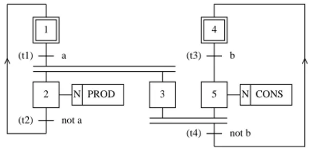
Let us consider the grafcet called ’sema’ (cf. figure 1). It represents a producer-consumer pattern. The ’a’ condition implies the production of an element and the ’b’ condition leads to its consumption.
(t1) (t2) (t3) (t4) 1 N PROD 5 N CONS 2 3 4 a b not b not a
Figure 1. sema producer-consumer pattern This example allows us to illustrate our different imple-mentation choices.
3.2. Sequential Grafcet : Finite state machine
The first and simplistic way to translate a sequential grafcet specification into a VHDL program is to identify each grafcet step with a state. Each grafcet transition is con-sidered as a transition of the finite state machine guarded by a transition condition. This is the classical implemen-tation technique used by API. It does not follow the basic rule about transition firing and introduces some gliches on actions. The inopportune setting in motion of the operative part is likely to cause serious personal accident or destruc-tion of the system. Moreover this approach could raise some technical translation problems with highly concurrent sys-tems because of the exponential state growth and should be given up.
3.3. Local behaviour modelling
This approach consists in expressing localGrafcet evolu-tion rules into concurrent equaevolu-tions. This is a very pedagog-ical way to understand Grafcet for students whose already know theVHDL language or another hardware description language. The translation is systematic and simple. Here are the five grafcet rules [12] and the both following sec-tions show two different implementasec-tions:
Rule 1 : The initial situation is characterized by the initial steps which are by definition in the active state at the beginning of the operation.
Rule 2 : A transition is either enabled or disabled. It is said to be enabled when all immediately preceding steps linked to its corresponding transition symbol are active, otherwise it is disabled. A transition cannot be cleared unless it is enabled and its associated transition condition is true.
Rule 3 : The clearing of a transition simultaneously leads to the active state of the immediately following step(s) and to the inactive state of the immediately pre-ceding step(s).
Rule 4 : Several transitions simultaneously clearable are simultaneously cleared.
Rule 5 : If during operation, a step is simultaneously activated and de-activated, priority is given to the acti-vation and the step remains active without interruption.
3.3.1 Work delegation to the Synthetiser
This approach simply consists in writing evolution rules as concurrentVHDLequations. The fourth evolution rule says that all simultaneously clearable transitions must be imme-diately and simultaneously cleared. Then for each transition ’ti’ we can write aVHDLequation ’Ti’ to represent cleara-bility of the transition. As specified by the second evolution rule, it depends on transition condition ’Ri’ and on conjonc-tion of preceding steps ’pre(ti)’.
-- A transition is clearable if and only if -- all of the preceding steps are acti-vated and
-- the transition condition is true. Ti <= pre(ti) and Ri;
-- pre(ti) is the conjonction of activation state -- of preceding steps.
-- Ri is the transition condition of ti.
The third evolution rule specifies consequences of a tran-sition clearing on preceding steps (de-activated) and follow-ing steps (activated). Then we can write the activation equa-tion ’Xi’ about each step ’xi’ as :
-- A step must be acti-vated if none of the following -- transitions are clearable
-- and either the step was yet activated -- or one of the preceding transi-tion is clearable.
Xi <= not succ(xi) and ( Xi or pre(xi) ); -- pre(xi) is the disjonction of the preceding -- transition clearability. -- succ(xi) is the conjonction of the following -- transition clearability.
Obviously, those equations suppose the existence of a stable state and will have a non-deterministic behaviour oth-erwise. When one stable state exists,VHDLsimulation rules guaranty a deterministic behaviour. Then one of the stable states will be reach in a bounded time (Number of state propagation delays into gates).
In order to be sure that actions are stable during a con-stant time and are always false during reset time we have to synchronise in a sequential process outputs.
Here is an abstract of the resultingVHDLprogram which behaves as the ’sema’ grafcet (cf. figure 1).
-- processing transition clearability. T1 <= a and X1;
T2 <= not a and X2; T3 <= b and X4;
T4 <= not b and X3 and X5; -- processing activation of steps. -- X1 : initial step
X1 <= reset or not T1 and (X1 or T2); X2 <= not T2 and (X2 or T1);
X3 <= not T4 and (X3 or T1); -- X4 : initial step
X4 <= reset or not T3 and (X4 or T4); X5 <= not T4 and (X5 or T3); -- sequential process process(clk, reset) begin if reset = ’1’ then PROD <= ’0’; CONS <= ’0’;
elsif clk’event and clk = ’1’ then PROD <= X2;
CONS <= X5; end if; end process;
The clock frequency has to be sufficiently low to guar-anty that one stable state is reached. The clock period should be higher or equal to the maximum of the reaction time.
3.3.2 Work delegation to specific tools
The main problem of the preceding solution is that we have to suppose that the stability state exists. But synchronous
language likeESTEREL[6] have already proposed some ap-proaches in order to solve boolean stability problems. So we developed a compiler called g2e [11] which translates a grafcet specification into an ESTERELprogram. Esterel is based on a well-defined mathematical formalism which al-lows users to establish logical correctness of programs in a formal way. Then we can use every tools based on VHDL
(simulator, code generator, model-checker). In particular some works to automatically generate hardware circuits was performed [5].
The proposed translation considers each step as a reac-tive system. Each step is able to react instantaneously to state modifications processed by other steps. Thus, the third evolution rule of Grafcet applied to steps 3,4 and 5 of ’sema’ can be written in Esterel as :
present RTL3 and RTL5 and not b then emit X4_SET;
emit X3_RESET; emit X5_RESET; end present;
where Xi SET and Xi RESET denotate respectively set and reset orders of activation about step xi. RTLi denotates the ’Ready to Leave’ signal which is emitted by the step xi if it is active.
Moreover, this translation allows the integration of Grafcet model as an entry of theESTERELframework. The combination of Grafcet andESTERELhas already and suc-cessfully been used to model and generate code of start and stop modes of a flexible production system [1].
Lots of previous works [9, 7, 10] encourage synchronous model designers to give up interpretation ’Without Search for Stability’ because it badly respects the basic postulates of the model and is not in adequation with the continuous actions semantics. Then, we completely give up this inter-pretation method and advocate to completely process the set of accessible stability states in accordance with [18]. Fi-nally, this set will have to be directly established in VHDL
as performed in the following section.
3.4. Global behaviour modelling
Compiling a Grafcet specification consists in translating a grafcet into another formalism. This behaviour of the re-sulting program must respect the initial behaviour specifica-tion. With that idea some numerous works of compilation was already performed (finite state automata [18], petri nets [17], transition systems and signal language [15], Electre Language [19]). We already developed our own compiler (G2OC). This compiler is able to compile any Grafcet spec-ification corresponding to safe-defined subset of the Grafcet model [2, 11]. The compiler looks for the set of reachable states and then generates the corresponding finite state au-tomata. As soon as the grafcet is computed not to be
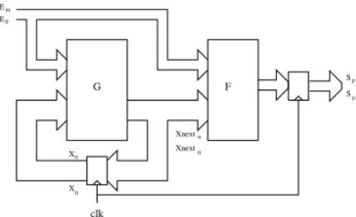
sta-E Em 0 Sp S 0 G n 0 X X Xnext Xnext F 0 n clk
Figure 2. the ’grafcet’ machine
ble, it is automatically rejected. Let us note, that the ex-plicit research of all accessibles situations often leads to an exponential growth of the number of states to be stud-ied. To avoid this bad behaviour, the compiler does not parse explicitely each input configuration but use a sym-bolic method based on binary decision diagrams (BDD) [8]) to compute boolean equations. Then the grafcet is said to be symbolically compiled. The complete and theoretical ex-planation about this method was already published in [11].
Then,G2OCis able to generate a boolean automata com-posed of a boolean vector which represents the current state and a boolean matrix representing possible transitions. Then we can efficiently manage the exponential growth. Each grafcet situation is associated to a specific value of the state vector. Each state equation concludes in one step about activity of a specific step. This equation only depends on other step state and inputs.
In such a way, when the grafcet is accepted, the gener-ate system can be seen as a combinatory system of equa-tions which establish the next activation state for each step. This combinatory system is combined with a sequential synchronous process to update at each instant the state of each step and the corresponding outputs. This is illustrated by the figure 2.
Using the VHDL pattern for sequential Mealy machine we can easily implement computed boolean equations into aVHDLprogram.
-- VHDL generation by g2oc from sema2 grafcet entity sema2 is
port(b, a, reset, clk: in bit; PROD, CONS: out bit); end sema2;
architecture sema2_a of sema2 is signal X1, X2, X3, X5, X4,
X1next, X2next, X3next, X5next, X4next :bit; begin
-- state and output computation process (clk,reset)
begin if (reset = ’1’) then PROD <= ’0’; CONS <= ’0’; X2 <= (a); X1 <= (not a); X3 <= (a); X5 <= (b); X4 <= (not b);
elsif ( clk’event and clk=’1’) then PROD <= (X2next); CONS <= (X5next); X2 <= X2next; X1 <= X1next; X3 <= X3next; X5 <= X5next; X4 <= X4next; end if; end process; -- future computation X2next <= (a); X1next <= (not a);
X3next <= (X1 and (X3 and X4)) or ...; -- X3next <= F3(X1,X2,X3,X4,a,b);
X5next <= (X1 and (X3 and b)) or ...; -- X5next <= F5(X1,X2,X3,X4,a,b);
X4next <= (X1 and (X3 and (not b))) or ...; -- X4next <= F4(X1,X2,X3,X4,a,b);
end sema2_a;
4. Conclusion
In this paper, we showed the interest to compile a Grafcet specification into a VHDL representation in order to al-low the realisation on a programmable component. Af-ter analysing of different constraints fixed by the Grafcet model andVHDLsynthesisers, we mainly proposed two im-plementation possibilities. Both approaches attempt to give an automatic way to translate a Grafcet specification into a
VHDLsynthesisable program. Obviously only the ’global
behaviour modelling’ approach gives satisfiable answers to
the following problems:
Performs a complete analysis of reachable states in or-der to directly process the next stable state after each transition in terms of the previous state and inputs. This considerably reduce the processing time and the area (number of logical cells needed in components). Allows some behaviour verification and validation of safety properties before synthesis.
In this paper, we studied the links between pro-grammable components and the Grafcet world. We hope this paper has brought both communities closer together.
References
[1] C. Andr´e and D. Gaff´e. Coop´erationGRAFCET/ESTEREL´ . In
Colloque AGI’94, pages 221–224, Poitiers, Juin 1994.
Asso-ciation AGI.
[2] C. Andr´e and D. Gaff´e. Ev´enements et conditions en
GRAFCET. A.P.I.I., 28(4):331–352, 1994.
[3] A. Arnold. MEC: a system for constructing and analysing
transition systems. volume 407. LNCS, Springer-Verlag,
1989.
[4] P. Aygalinc and J.-P. Denat. Validation de mod`eles
GRAFCET fonctionnels et ´evaluation de performances du syst`eme associ´e par l’utilisation des r´eseaux de petri. pages 135–145, Paris, Mars 1992. Conf´erence Grafcet’92, Afcet.
[5] G. Berry. A hardware implementation of pureESTEREL.
Miami, January 1991. ACM Workshop on Formal Methods in VLSI Design.
[6] G. Berry. The Foundations of Esterel. MIT press, available
on the web, www-sop.inria.fr/meije/esterel,
Sophia Antipolis (F), 1998.
[7] N. Bouteille, P. Brard, G. Colombari, N. Cotaina, and
D. Richet. Le GRAFCET. C´epadu`es Editions, France, 1992.
[8] R. E. Bryant. Graph-based algorithms for boolean
func-tion manipulafunc-tion. IEEE transaction on Computers,
C-35(8):677–691, 1986.
[9] R. David and H. Alla. Du GRAFCETaux r´eseaux de Petri.
Automatique. Herm`es, Paris, 1989.
[10] P. Delanchy. Obtention des situations stables par calcul an-ticip´e des transitions franchissables dans un grafcet. pages 193–202. Mod´elisation des syst`emes r´eactifs (MSR’99), Cachan, France, March 1999.
[11] D. Gaff´e. Le mod`ele GRAFCET: r´eflexion et int´egration
dans une plate-forme multiformalisme synchrone. PhD
the-sis, Universit´e de Nice-Sophia Antipolis, Janvier 1996. [12] IEC, Gen`eve (CH). Preparation of Function Charts for
con-trol systems, december 1988. International standard IEC
848.
[13] IEEE, 345 East 47 th Street, New York, NY 10017 USA.
IEEE standard VHDL Language Reference Manual, 1987.
IEEE Std 1076-1987.
[14] J. L. J.F. Hery. S´emantique fonctionnelle et stabilit´e du
grafcet sous l’hypoth`ese du synchronisme fort. pages 263– 274. Mod´elisation des syst`emes r´eactifs (MSR’99), Cachan, France, March 1999.
[15] P. Leparc, D. L’her, J.-L. Scharbarg, and L. Marce. Grafcet
revisited with a synchronous data-flow language. IEEE
transaction on Systems, Man and Cybernetics - Part A: Sys-tems and Human, 29(3), May 1999.
[16] J.-J. Lesage, J.-M. Roussel, J.-M. Faure, P. Lhoste, and J. Za-ytoon. R´eactivit´e et d´eterminisme du comportement tem-porel du grafcet. pages 99–106. Automatisation des proces-sus mixtes (ADPM’98), Reims, France, March 1998. [17] M. Moalla. R´eseaux de petri interpr´et´es et grafcet. Rairo
Automatique, 4(1):17–30, 1985.
[18] J. M. Roussel. Analyse de Grafcets par g´en´eration logique
de l’automate ´equivalent. PhD thesis, ´Ecole Normale Sup´erieure de Cachan, d´ecembre 1994.
[19] O. Roux and V. Rusu. Du GRAFCET au langage r´eactif