CATALYTIC HYDRODEMETALLATION OF NICKEL PORPHYRINS: REACTIVITY AND
CATALYST SURFACE STUDIES by
Ian Alexander yebster
B.Sc., University of Strathclyde (U.K.) (1976)
M.S., Cornell University (1979)
Submitted to the Department of Chemical Engineering in Partial Fulfillment of the
Requirements for the Degree of
DOCTOR OF SCIENCE at the
MASSACHUSETTS INSTITUTE OF TECHNOLOGY February 1984
0 Massachusetts Institute of Technology 1984
Signature of Author
Department of Chemical Engineering January 13, 1984 Certified by James Wei Thesis Supervisor Accepted by Robert C. Reid Chairman, Departmental Committee on Graduate Students
MASSACHUSETTS INSTITUTE OF TECHNOLOGY
MAR 0 8 1984
CATALYTIC HYDRODEMETALLATION OF NICKEL PORPHYRINS: REACTIVITY AND CATALYST SURFACE
STUDIES
by
IAN ALEXANDER WEBSTER
Submitted to the Department of Chemical Engineering on January 13, 1984 in partial fulfillment of the
reuirements for the Degree of Doctor of Science in Chemical Engineering
ABSTRACT
The kinetics and mechanism of hydrodemetallation (HDM) of nickel
etioporphyrin (NI-EP) and nickel tetra(3-methylphenyl) porphyrin (Ni-T3MPP) have been studied using alumina supported Group VIII metals, Co-Mo, and Ni-Mo as catalysts, and a white oil as a solvent. The metalloporphyrin solution simulates a metals containing residua, and was demetallized at
1000 psig H and temperatures in the range 300 to 375*C. Over all
catalysts, goth porphyrins react via a sequential mechanism, involving initial hydrogenation to activate the porphyrin, followed by terminal hydrogenolysis which cleaves the ring, and deposits nickel onto the catalyst surface. While the global HDM mechanism is the same for both porphyrins, the intricacies of the HDM scheme are intimately linked to the structural differences on the periphery of the tetra-pyrrolic ring. With the Group VIII metals/Y-Al 0 the selectivity of the HDM mechanism
(terminal hydrogenolysis riti constant/initial hydrogenation rate constant) has been varied over two orders of magnitude. Group VIII metals favor hydrogenolysis, while the Group VIII metals have a high ;electivity for hydrogenation. The HDM activity of lhe Group VIII metals is comparable to that of Co-Mo.
Ni-EP was reacted over a series of Ru-Cu/Al 0 catalysts. The addition of Cu to the Ru system suppresses the rate of ih hydrogenolysis reaction, while having little effect on the hydrogenation reaction. Based on XPS measurements these observations were rationalized by geometrical effects. XPS also indicated that the chemical state of nickel deposited on a
catalyst via HDM differs from its state and degree of interaction with the support in a Ni-Mo/Al203 catalyst.
Oil soluble cobalt and molybdenum napthenates were also dissolved in the white oil, and demetallized over bare T-Al 0 support at temperatures of
290*C and 360*C, and pressures of 500 and 1000 psig H2. These in situ synthesized Co-Mo catalysts were subsequently used in Ni-T3MPP HDM. The catalysts which were generated at 360*C, 1000 psig H2 had a higher Ni-T3MPP
AES measurements indicate that a thick carbonaceous overlayer envelopes the Al 0 particles during napthenate demetallation. However this overlayer
remaPns porous enough to permit all metals to ultimately deposit on the alumina.
Model, non-porous polycrystalline alumina supported Co-Mo catalysts were made with surface compositions in the range 0<[Co/(Co+Mo)]<1 and used for
Ni-T3MPP HDM. The catalysts were aged in HDMexperiments Tn a spinning basket reactor at 360*C and 1000 psig H The aged catalysts were scrutinized by a variety of surface spe~troscopic techniques (XPS, AES, SIMS, ISS and SEM/EDX). HDM activity was a maximum in the range
0.5<[Co6{Co+Mo) <0.7. Thf~initia1ly oxidic catalysts were reduced during HDM (Mo to Mo , and Co to Co ). Both metallic Ni and NiO were
observed on the aged catalysts, however, the latter entity is most probably a result of air contamination, and it is not present in the working HDM environment. ISS results were consistent with the existence of a Co-Mo double layer, in both the real y-Al 0, supported catalysts and the model catalysts, with a Mo rich layer resid ng atop a Co rich layer. The basic elements Na and K are strongly surface segregated and in intimate contact with the Mo, thereby moderating its acidity. The aged catalyst is covered with a carbonaceous overlayer possessing holes, through which bare Mo patches are exposed. These islands are speculated to remain coke and metals free as the catalyst operates. A conceptual model for the working
hydrotreating catalyst surface is proposed which integrates all surface spectroscopic findings. The model emphasizes the hydrogen storage and exchange capabilities of the carbonaceous overlayer which must be viewed as an integral feature of the working catalyst surface.
Thesis Supervisor: Dr. James Wei
Department Head and Warren K. Lewis Professor of Chemical Engineering
to my mother and father Charles and Helen Webster
whose encouragement and understanding through my long education has been
ACKNOWLEDGEMENTS
Many people have contributed to the final state of this thesis. I wish to thank:
* my thesis supervisor Professor James Wei, and thesis committee of Professors Charles N. Satterfield, Michael P. Manning, Adel F. Sarofim, Robert C. Reid, Herbert H. Sawin, Sylvia T. Ceyer and Dr. Frederick A. Putnam;
* The Department of Chemical Engineering and the National Science Foundation for financial support;
* for analytical assistance, John R. Martin, MIT, (XPS,AES); Leonard I. Sudenfield, MIT, (SEM/EDX); Dr. Chi-Wen Hung, Chevron Research Co.,
(Hydrogen chemisorption); Dr. Alan Miller, Alcoa Research, (ISS, SIMS); Dr. Elizabeth Myers, American Cyanamid Research, (Co-Mo catalyst
supplies and their characterization);
* my future employer, Union Oil Company of California, especially Dr. J. Wayne Miller, for understanding the delays I experienced during this last year of my thesis work;
* my friends (in no particular order, of course), Bob Ware, Shan Hsi Yang, Morris Smith, Chris (have a beer) Schwier, Mark Manton, Kent Goklen, George Corbin, Norm Margolus and Deb Dickinson. The nights we conducted fluid mechanics research from Harvard Square to Downtown to Route 2 to Chelsea to East Boston to the Big Dipper are indelibly etched in the
scars on my body; "It doesn't get any better than this."
Chapter I. The Hydrodemetallation of Nickel Porphyrins
Catalyzed by Group VIII metals/Y-Al203: Mechanism Reactivity and Selectivity
I.A. Summary of Chapter I.B. Introduction
I..C. Experimental
I.C.1. Experimental Apparatus I.C.2. Materials
I.C.3. Hydrodemetallation Experiment-Procedure I.C.4. Analytical
I.D. Results
I.D.1. Ni-Etio porphyrin HDM over Group VIII met I.D.2. Ni-tetra(3-methylphenvl) Dorphyrin HDM ov
I.E. I.F. I.G. Chapter II. II.A. II.B. II.C. I.D.3. I.D.4. Di scussi Conclusi Referenc als
Group VIII metals
Post HDM experiment catalyst characterization
-Ni-Etio porphyrin HDM over Group VIII-IB metals on
ons
es
The Synthesis of Co-Mo/Al,03 Catalysts for Hydrodemetallation (HDM) 9f Heavy Oils by Metal Napthenate Demetallation over Y-Al 0 . Their activity measurements and charactefilation
(SEM/EDX,AES) in the HDM of nickel
tetra(3-methylphenyl) porphyrin Summary of Chapter Introduction Experimental Page 10 10 11 22 22 22 30 33 36 36 60 73 81 88 95 96 101 101 102 106 N". .
II.D. Results
II.D.1. Kinetic Measurements II.D.2. Catalyst Characterization II.E. Discussion II.F. References Chapter III.E. III.F. III.G. III.H. Discussion
A Conceptual Model for the Working Co-Mo/A1203 Hydrotreating Catalyst
Conclusions References
III. The Catalystic Hydrodemetallation (HDM) of a Model Oil over Polycrystalline Alumina
Supported Co-Mo Catalysts. A surface Study
by AES, XPS, ISS, SIMS and SEM/EDX, and a
Conceptual Model for the Working Hydrotreating Catalyst
-III.A. Summary of Chapter III.B. Introduction
III.C. Experimental
III.C.1. Catalysts and their Preparation III.C.2. Oil
III.C.3. Reactor III.C.4. Procedure
III.C.5. Analysis III.D. Results
III.D.1. AES on LPCA catalysts III.D.2. XPS and HPCA catalysts
III.D.3. ISS and SIMS on HDS-16A, LPCA and
HPCA catalysts
III.D.4. SEM/EDX investigation of aged LPCA and HPCA model catalysts
117 117 136 145 153 156 156 157 163 163 168 169 172 176 180 180 185 198 214 222 236 248 251
Chapter IV. IV.A. IV.B. IV.C. IV.D. IV.E.
Intrapellet Nickel Profiles Obtained in the Hydrodemetallation (HDM) of Nickel
tetra(3-methylphenyl) porphyrin (Ni-T3MPP) over Co-Mo/Al 0 The Presence of Pd/Al20
and its Effeci ?n Eliminating Pore Mouth Piugging Summary of Chapter
Introduction Experimental
Results and Discussion References 257 257 257 259 260 266
PREFACE
Each chapter in this thesis is self-contained. They each have their own summary, literature review, experimental, discussion, and reference sections. For the sake of brevity, the thesis contains no raw data directly from the many hundreds of batch experiments which were run. Copies of these numbers are held by the author at Union Oil Research Center, Brea, California, and by Professor James Wei, MIT.
The Hydrodemetallation of Nickel Porphyrins Catalyzed by Group VIII metals/
Y-Al203: Mechanism, Reactivity
and Selectivity
I. A. Summary of Chapter
The kinetics and mechanism of hydrodemetallation (HDM) of nickel etioporthyrin (Ni-EP) and nickel tetra (3-methylphenyl) porphyrin
(Ni-T3MPP) have been studied using alumina supported Group VIII metals as catalysts, and a white oil as a solvent. The metallo-porphyrin solution simulates a metals containing residua, and was demetallized at 1000 psig H2
and temperatures in the range 315-375*C. Both porphyrins react in a sequential mechanism, involving initial hydrogenation to activate the
porphyrin, and deposits nickel onto the catalyst surface. While the global HDM mechanism is the same for both prophyrins, the intricacies of the HDM scheme are intimately linked to the structural differences on the periphery of the tetra-pyrrolic ring. By using Group VIII metal /Y-Al203 catalysts we have been able to vary the selectivity of the HDM mechanism
(hydrogenolysis rate constant/hydrogenation rate constant) over two orders of magnitude, at best. This behavior correlates with the percentage
d-character of the Group VIII metal. The HDM activity of the Group VIII metals is comparable to that for Co-Mo/A1203, to which we compare our data.
11
the copper is perceived as an inert "spacer" element which divides up ensembles of ruthenium atoms required for the porphyrin hydrogenolysis reaction. Addition of copper to the ruthenium catalyst suppresses
hydrogenolysis while having little effect on the hydrogenation reaction. These observations have been interpreted in terms of geometrical effects. XPS measurements on the aged Group VIII metal catalysts suggests that the
catalytically deposited nickel does not interact strongly with the support. I. B. Introduction
One of the major refining technological challenges of the 1980's is the conversion of heavy residual oils into lighter fuel oils. During the hydrotreating operation the heavy oils' heteroatoms, sulfur, nitrogen, oxygen and trace metals (chiefly, Ni, V. and Fe) are catalytically cleared
from the oil. S. N and 0 leave via the gas phase as H2S, NH3, and H20
while the metals irreversibly deposit on the hydrotreating catalyst. This catalyst is usually Co-Mo/Al203'
The metals are particularly troublesome, and can be present in concentrations as high as 1300 ppm by weight Ni and V (1). During hydrotreating these metals deposit on the catalyst causing fouling of active sites, which leads to rapid catalyst deactivation. At longer
operating times the metals cause pore mouth plugging, thereby occluding the less severely poisoned interior volumes of the catalyst.
The nickel and vanadium compounds in heavy oils are present as oil soluble organic species, and can be classified into two groups namely, the metallo-porphyrins and the non-porphyrinic metals. Since in real crudes, metal in the porphyrin form can account for up to 50% of the oil's total metal content (2), metallo-porphyrin spiked oils represent an ideal model
crude, with which to investigate the hydrodemetallation (HDM) kinetics of real oils.
The approach of our research group has been to investigate the
catalytic HDM of a model crude synthesised by dissolving Ni-porphyrins in a clean, sulfur and nitrogen free white oil. The kinetics and mechanism of HDM have been investigated. There is a definite need for such model
compound studies in order to clarify the conflicting and incomplete studies of previous investigators.
For example, Riley (3) observed apparent first order removal kinetics for both nickel and vanadium. Higher order demetallation kinetics were reported by Van Dongen et al (4), such as 1.5 order for vanadium. Oleck and Sherry (5) reported second order HDM kinetics for both Ni and V. With real crudes the presence of more than one class of metal compound, reacting with different rates make it impossible to determine the true kinetic
orders, rate parameters and mechanism of the HDM reactions.
Model compound HDM studies were pioneered by Hung and Wei (6,7) who demetallized both nickel and vanadyl porphyrins over an oxide Co-Mo/Al203
catalyst. Total metal removal rates were found to follow fractional order kinetics. This observation was subsequently interpreted by Agrawal and Wei
(8) to be the result of a sequential HDM mechanism, with the final metal
deposition step occurring via an hydrogenated intermediate not originally present in the oil. More recently Ware and Wei (9), Rankel (10,11) and Kameyama and Amano (12) have investigated the HDM kinetics and reaction pathways of nickel and vanadyl porphyrins with model compounds. All their work confirms the sequential nature of the HDM mechanism.
13
aforementioned studies was Co-Mo/Al203 (13). Co and Ni-promoted Mo and W
catalysts are also popular (14). However, as petroleum feedstocks dwindle, there is an ever increasing need to formulate, experimentally investigate, and develop a new generation of highly selective hydroprocessing catalysts.
The objectives of this work have been to experimentally investigate the kinetics of model oil HDM reactions over afumina supported Group VIII metal catalysts, and a Group VIII-IB bimetallic catalyst, namely
Ru-Cu/Al203. The rationale for why this merits investigation is developed
in the following literature review section. We believe this to be one of the first studies investigating catalytic HDM over supported Group VIII metal s.
I. B. 1. Literature Review and Research Rationale
Recent work from our laboratory has shown how during catalytic HDM the porphyrins react via a sequential mechanism, first involving hydrogenation
of peripheral double bonds, followed by a final hydrogenolysis step which fragments the ring, and removes the metal. Agrawal and Wei (8)
demetallized Ni-etioporphyrin (Ni-EP) (for structure see Fig. 1) at realistic hydrotreating process conditions (290-345*C, 600-1400 psig hydrogen) over Co-Mo/Al203 catalyst. Only one hydrogenated intermediate
called Ni-EP chlorin (Ni-EPH2) was observed. The Ni-EPH2 then reacted via
a hydrogenolysis step which cracked the ring and deposited the metal on the catalyst surface.
Subsequently Ware 'and Wei (9) experimented with the HDM of Ni-tetra (3-methylphenyl) porphyrin (Ni-T3MPP) (Fig. 1). This investigation permitted a comparison with the Ni-EP HDM kinetics and mechanism. Both porphyrins have similar four pyrrole ring macro structures and conjugation,
14
N
N
Ni-ETIOPORPHYRIN(Ni-EP)
0
N NNi-TETRA(3-METHYLPHENYL)PORPHYRI.N
(Ni-T3MPP)
Structure of model nickel compounds
15
but have structural differences around the periphery of the macrocycle. Ni-EP has methyl, and ethyl groups on the -pyrrolic positions and open methine bridges, whereas, Ni-T3MPP has open -pyrrolic positions and tolyl substitutents at the methine bridges.
Ware and Wei's study (9) revealed that while the general scheme of porphyrin hydrogenation followed by porphyrin hydrogenolysis and metal deposition was maintained, the reaction pathways for the two porphyrins were different. Ni*-T3MPP reacted through two hydrogenated porphyrin intermediates (Ni-T3MPP chlorin [Ni-T3MPPH2] and Ni-T3MPP
isobacteriochlorin [Ni-T3MPPH4]) and a non-porphyrinic, contracted ring structure. Moreover, the Ni-T3MPP HDM pathway has shown to possess two routes for metal deposition: one from Ni-T3MPPH and the other from the contracted ring structure, which Ware (15) has speculated to be an hydrogenated nickel-corrin (16).
Because of the bifunctional nature of the HDM mechanism (initial
hydrogenation followed by terminal hydrogenolysis) we sought catalysts that would permit us to vary the selectivity or, hydrogenolysis to hydrogenation
rate constant ratio, in the HDM pathway. The benefits of being able to realize this are obvious. A catalyst that can hydrogenate the porphyrin, but is relatively poor for its hydrogenolysis, can be used to conduct the mandatory hydrogenation step(s), but ultimately have little nickel
deposited on it, because of its relatively low cracking activity. The process implications are that the hydrogenation reactions could be carried out in upstream catalyst bed. The hydrogenated metallo-prophyrinic
intermediates would then be passed over another catalyst, in a downstream bed, which possessed a high hydrogenolysis activity. Nickel would be
16
deposited in this bed. The pore size distribution of this latter catalyst would be engineered so that it could acummulate a heavy nickel loading without encountering problems of pore mouth plugging (17, 18).
Supported Group VIII metals and supported Group VIII-IB bimetallic catalysts have been shown to have widely varying activities for conducting hydrogenation and hydrogenolysis reactions.
Pioneering work on the relative activities of the Group VIII metals for hydrogenation and hydrogenolysis was conducted by Sinfelt and coworkers
(19-25). Two relevant pieces of information from their investigations,
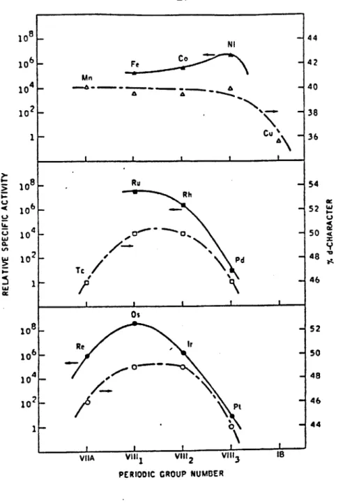
which we exploit in this study, are depicted in Figs. 2 and 3. Sinfelt et al, used ethane and cyclopropane as the test molecules for measuring
hydrogenolysis and hydrogenation rates respectively. Figure 2 shows the catalytic activities of the Group VIII metals for ethane hydrogenolysis as a function of their periodic position. Within each transition series
hydrogenolysis activity varies dramatically (ca. six orders of magnitude in the second and third transition series), and can be broadly correlated with the percentage d character of the metallic bond. This quantity is
introduced in Pauling's valence bond theory of metals to represent the extent of participation of d orbitals in the bonding between atoms in a metal lattice (26). This parameter has no clear physical significance
(27), and has come under considerable general criticism (28, 29).
Nevertheless, the hydrogenolysis capabilities of the Group VIII are remarkably well correlated with percentage d character. For example, Boudart and Ptak (30) measured the rates of hydrogenolysis of neopentane on supported Group VIII metal catalysts, and successfully correlated the catalysts' activity over ten orders of magnitude, with percentage d-bond
17 10 8 _ Ni 44 10 6 - Fe - 42 Mn 10 4 - . - 40 102- 38 1 - Cu 36 I I I I 8 Ru 54 Rh o6 _ 52 wI-' 10 4_a 0, 50 .4 w 10 x Os 10 8- 52 106 - Rr 50 104- 48 10 2- Pt -46 1-11 0
VISA VillI Vill2 VilI3 I
PERIODIC GROUP NUMBER
Figure 2: Catalytic activities of metals for ethane hydrogenolysis in relation to the percentage d-character of the metallic bond. From Ref. 20.
18
character.
Figure 3, taken from the work of Dalla Betta et al (25) compares the activity patterns of the 3rd transition series of the Group VIII metals for cyclopropane hydrogenation and ethane hydrogenolysis. Platinium has high activity for hydrogenation, however is relatively poor for hydrogenolysis. Moving in the direction of decreasing atomic number across the third
transition series triad from platinium to iridium to osmium, the metals' hydrogenation capability decreases while its hydrogenolysis activity increases.
It is evident that by using these Group VIII metals in an HDM pathway, incorporating both hydrogenation and hydrogenolysis steps, it may be
possible to manipulate a priori the selectivity of the mechanism, based on which particular catalytic metal is chosen. This is the first goal of the
research reported here.
In one of the most exciting catalytic developments of the past decade, catalytic chemists have also shown how the selectivity of high dispersed supported Group VIII-IB bimetallic catalysts depends on the atomic ratio of the Group IB element to the Group VIII element. The first significant work in this area was also accomplished by Sinfelt and coworkers (31).
Working with unsupported nickel-copper alloys as catalysts, Sinfelt et al (32) investigated the hydrogenation of cyclohexane to benzene, and the hydrogenolysis of ethane to methane. Their results are shown in Fig. 4. The hydrogenolysis activity is seen to decrease by approximately five
orders of magnitude, as the atom % copper is increased from 0 to 74%, while the rate of cyclohexane dehydrogenation remains "fairly insensitive" to alloy composition.
19
to 4
is I
Figure 3: Comparison of activity patterns of for cyclopropane hydrogenation and Ref. 25. * I I I I CYCLONEXAMEKYDOGCCWI % 0 S 40S 0 Molxs 1coa
-*
- tCIAUCt WvynSUCtoWSs. -0 I I I I I * so 40 AS so a aigs a gomggthe Group VIII noble metals ethane hydrogenolysis. From
Figure 4: Activities of copper-nickel alloy catalysts for the
hydrogenolysis of ethane to methane, and the dehydrogenation of cyclohexane to benzene. From Ref. 32.
Os Ir Pt I V U ~ leg N li 103 I. 10S 10 - 40 t o I 20-I
These observations can be explained by each of. the two theories
currently in vogue to rationalize the catalytic capabilities of bimetallic catalysts; namely the geometrical theory and the electronic theory (33-36). The geometrical theory assumes that "multiplets" (37) or "ensembles"
(38,39) of the catalytically active metal atoms (Group VIII) are required
to form an active catalytic site (40), where the reactant molecule
chemisorbs in a particular configuration before undergoing rearrangement. The role of the inactive Group IB metal is therefore perceived to be solely that of a diluent, which due to its ability to surface segregate (lower heat of sublimation (40-42)) destroys active metal ensembles. Due to this phenomenon the rates of reactions which require the presence of surface multiplets are therefore dramatically reduced by alloying inert spacer atoms, compared to reactions which simply proceed through chemisorption on a single active atom.
It is also reasonable to expect that the electronic energy level of an active metal atom will be affected by the contiguous presence of an
inactive metal atom (43,44). Such ideas are the basis of the "ligand" or electronic theory of catalysis by bimetallics. The spacer atom (Group IB) will affect the reactants' chemisorption bond strength, since its heat of adsorption on either of the two metals will differ. Since the strength of the bond(s) of the reactant to the active catalytic metal can be correlated to catalytic activity (45), it is evident how alloying can alter the
reactant turnover at a particular site.
Sinfelt et al (32) expained the rapid decline in hydrogenolysis activity and the insensitivity of hydrogenation activity to catalyst composition by invoking both the geometrical theory (Ni duplets are
21
required for chemisorption of hydrogen deficient dicarbon surface residues and their number is reduced by alloying) and the electronic theory (the electronic effect of Cu on Ni is to reduce its percentage d character, whose magnitude, as already discussed has been proposed as being directly proportional to the hydrogenolysis activity of the Group VIII metal
(19,22,24,30,46)).
Reactions that proceed through chemisorbed intermediates that are bound to many adjacent catalytically active atoms, are inhibited more strongly by alloying than reactions which only require small ensembles. The former reactions are structure sensitive, while the latter tend to be structure insensitive (47). Ponec (34) has noted that structure
insensitive reactions such as hydro-dehydrogenation are little affected by the introduction of inert Group IB metal atoms on the catalyst's surface, while structure sensitive reactions involving C-C bond dissociation are affected.
It is highly probable that some of the reactions involved in the
catalytic HDM of nickel porphyrins are structure sensitive, since the large porphyrinic tetra-pyrrole plate will most likely form multiple bonds at the catalytically active site. We can envision the hydrogenated form of the porphyrin molecule forming a multiply bonded intermediate prior to the ring opening step which releases the nickel atom onto the catalyst surface, and
leaves cracked fragments of the porphyrin ring bonded to adjacent active sites.
Our previous research (8,15) also substantiated by work in this paper, has elucidated the HDM mechanism. Nickel porphyrin hydrogenation is
structure insensitive, while the latter is structure sensitive. The second goal of our research is now evident. We will show how it is possible to control the selectivity of the HDM mechanism by exploiting the ability of bimetallic catalysts to suppress the rates of hydrogenolysis reactions, while having little affect on the rate of the simultaneously occurring hydrogenation reaction. XPS measurements on low surface area
polycrystalline alumina (PCA) supported bimetallic catalysts, indicate that
the effect of the Group IB metal is mainly geometrical. I. C. Experimental
I. C. 1. Experimental Apparatus
The kinetics of HDM was studied with batch autoclave experiments. The reaction vessel is a standard one liter batch autoclave (Autoclave
Engineers, Erie, PA, Model AFP 1005). The entire system is exactly as described elsewhere (6), except that an additional discharge line with a
0.5p filter was positioned at the bottom of the reactor. This permitted the reactor's contents to be quickly discharged, while retaining the catalyst in the reactor for a subsequent demetallation experiment. I. C. 2. Materials
(a) Catalysts
The chemical properties of the catalysts, and alumina used to make some of the catalysts are detailed in Table 1. For the catalysts actually employed in HDM experiments the support material was always Y-Al2 0 The Co-Mo and Ni-Mo hydrotreating catalysts (HDS-16A and HDS-9A) were supplied
by American Cyanamid (Bound Brook, NJ) as 1/16" diameter extrudates. Prior
to use the extrudates were crushed and sieved to the size range 75-90-P.
23
Table 1: Summary of Catalysts Investigated in HDM study
Catalyst Composition Supplier Cu/Ru atomic
System* (wt %) or Self ratio in Group VIII-IB Made bimetallics Co-Mo(HDS-16A) Ni-Mo(HDS-9A) Co Ni Ru Rh Pd Re Os Ir Pt Ru-Cu coo C003 MoO3 Na20 Fe Ni 0 MoO3 Na2 0 Fe SO 4 Sio2 5 5 5 5 5 5 5 5 5 Ru 5, Ru 5, Ru 5, 5.7 12.1 0.03 0.04 3.2 17.5 0.03 0.03 0.4 0.5 Cu 0 Cu 1.57 Cu 3.14 American Cyanamid American Cyanamid Strem Harshaw Strem Strem Strem Strem Self made Self made Strem Self made Self made Self made 0 0.5 1.0
*All catalysts supported on Y-A1203 (>99.85 wt %; Na20<0.015; SiO2< 0.09; Fe203<0.06 wt %)
24
metal, and were purchased from Strem Chemicals (Newburyport, MA) with the exception of the iridium and osmium catalysts. These catalysts were
prepared by individually impregnating y-A1203 (Norton Co., Akron, OH) with solutions of IrCl3. 3H20 and OsCl3 (Aldrich Chemical Co., Milwaukee, WI). During impregnation approximately 1 ml of the aqueous impregnating solution of appropriate concentration was employed per gram of alumina (48).
The alumina supported Ru-Cu bimetallic catalysts of the compositions listed in Table 1 were prepared by a simple co-impregnation procedure, using aqueous salts on acids of the two metals in question. The compounds used were RuCl3 (Aldrich Chemical Co.) and Cu(NO3 )2. 3H20 (Aldrich).
Solutions of the first of these compounds were prepared by dissolving the salt in 38% hydrochloric acid solution (Ashland Chemical Co.) to prevent hydrolysis of the salt, and the precipitation of the metal hydroxide.
After impregnation, all the self made Y-Al203 supported catalysts were then essentially treated similarly. They were all dried overnight at ca.
100C in air, with the exception of the osmium catalyst which was dried in
a vacuum oven at ca. 700C. Each resulting catalyst cake was reground and sized to 75-90w prior to being placed in a fused silica boat, which was then positioned in a tube furnace. The catalyst was reduced in flowing hydrogen at 5006C for approximately three hours prior to the HDM
experiment. The catalysts were also prereduced before catalyst
characterization by hydrogen chemisorption. A few runs were also made with the oxide forms of the Group VIII metal catalysts (i.e. no pre-reduction).
A series of polycrystalline alumina (PCA) supported Ru-Cu bimetallic
catalysts were also prepared, purely for use in XPS measurements. We have shown elsewhere (49) that these low surface area catalysts realistically
25
mimic the catalytic behavior of their high surface area Y-Al203
counterparts, and are more amenable for study in the ultra high vacuum environment of XPS. The preparation procedure has alreay been outlined in detail (49). Briefly, 1 cm2 slabs of non-porous PCA (99.9% Al203, Grade
AD-999, Coors Porcelain Company) were meticulously cleaned by alternate
soakings in chromic acid-sulfuric acid cleaning solution (Fisher Scientific Company) and distilled water. The PCA squares were calcined at 600'C in ultra high purity air (Matheson, Zero Gas), and subsequently co-impregnated with a carefully monitored volume of 38% HCl solution containing the
desired amounts of the aforementioned salts of Ru and Cu. Trial-and-error experimentation showed that 30l of liquid was an optimum volume to deposit on the PCA square from a syringe. This liquid puddle was swirled on the
PCA square with the syringe needle tip in an attempt to produce a uniform
coating of the impregnate on the alumina surface. A uniform surface coating was difficult to attain, and this point will be further amplified later. Each PCA catalyst was then treated identically to the self made Y-Al203 supported catalysts, i.e. dried at 100*C overnight in air, then reduced at 500*C for three hours in flowing hydrogen. Immediately prior to XPS analysis the model catalysts were again reduced, and carefully
transferred to the ultra high vacuum environment of the spectrometer in a glove bag, under an Argon atmosphere. Every attempt was made to avoid air contamination of the catalysts. The compositions of the PCA supported catalysts that were prepared are listed in Table 2. The 30P1 solution volumes that were spread over each PCA square contained enough of the Group VIII metal such that if it was to uniformly coat the surface, 30 monolayers of the metal would exist. With catalysts which contained copper, the
for investigation by XPS
Catalyst Number Metals Composition
1 Ru 30 monolayers
2 Cu 30 monolayers
3 Ru-Cu Cu/Ru atomic ratio = 1
30 monolayers Ru
27
ruthenium metal loading was the same, with sufficient copper being added to make the [Cu/Ru] atomic ratio equal to unity. While these model PCA
catalysts are far more heavily surface loaded than the Y-A1203 supported
catalysts detailed in Table 1, we nevertheless believe they represent good idealizations of the real catalyst surface, and are especially amenable to scrutiny by XPS.
The pore size distributions (PSDs) of all Group VIII metal catalysts were measured by nitrogen adsorption (Digisorb 2500). Some typical
distributions are depicted in Fig. 5. All catalysts possessed similar
physical properties. The PSDs of of the American Cyanamid supplied Co-Mo/Al203 catalyst, and the Norton Y-A1203, each measured by mercury
penetration, are reported in Fig. 6.
(b) Model metal compound and oil
Model nickel containing heavy oils were synthesized by dissolving Ni-Etioporphyrin (Ni-EP) and Ni-tetra (3-methylphenyl) porphyrin (Ni-T3MPP) individually in a clean mineral oil. The porphyrins were purchased from Midcentury Chemicals (Posen, IL) and the mineral oil, marketed under the name Nujol, from'Plough Inc. (Memphis, TN). The molecular structures of the porphyrins are shown in Fig. 1. The metallo etioporphyrins are found in petroleum (50), whereas the metallo tetra-phenyl porphyrins are not. However, they are probably more representative of condensed porphyrins of
higher aromaticity which have been speculated as comprising the asphaltene component of residua (51).
The composition of the mineral oil has been described by Fiero (52), and although it is a mixture of several hydrocarbons, it consists only of
A40 .36 .30 .25 .20 .15 .10 0 RELATIVE PRESSURE Pi PO Q2 Q4 Q6 Q8 0.90 Q9 Ru(5%) 1A1203 BET AREA; 97 m2 CUMULATIVE AREA TO 3nm 14& m2Ig N2 PORE VOLUME<100nm: 0.2628 m ig
RU
- -- I 2 5 10 20 PORE DIAMETER,(nm) t2 4 4 12 w 0 3. 0.8 E 50 100RELATIVE PRESSURE PIPO 02 0.4 0.6 8 Q9 Q94 Pd(6%) IA203 - BET AREA:119 m2 Ig CUMULATIVE AREA.AO 3nm:163m21g .30- N 2 PORE VOLUME < 100 nm -Q2304 mf i 1.2 20- -0A 20
Pd
jo
- OA 0 10 2 6 10 20 PORE DIAMETER. (nmJRELATIVE PRESSURE P/PO
0.40 2 04 0. 0 i 0.94 1.6 Rh(6%) A12 03 SET AREA: 106 m2 CUMULATIVE AREA TO 3nm: 161 m2ig -t2 0.30 -N2 PORE VOLUME (100 n: 0.2418 mIg 4.20
-Rh
0.10 0 2 6 10 20 50PORE IDIAMETER (n)O
w 2 g w CA 2S 0> w 0 -90 I 0 Sn
Ii..-Figure 5: Pore size distributions for Group VIII metal catalysts Ru, Pd and Rh on Y-Al203' U *1 Li 2: -J 0 3. hi S 0 A. LA 3. 0.. ( ..1 2: U E 0 *0a 0 -h I
I
le 3. 2 U . 50 10029
MERCURY PRESSURE (PSIA)
Co-Mo
0 0 0 0 0 0 0.4 0.3 0.2 442 0 0 0 0 176.8 117.8 88.4 70.7 59.0 44.2 35.4Pore Diameter (Angstroms)
Pore Diameter (Angstrons)
0 0 I I I I I
Alumin
'4 -4 &4 M 'I 4.. .4. a -4 .4 4. U U -. 4 *0a
0 I I III~1I- I a I 1111.1 Pressure (PSIA)Pore size distributions for Co-Mo/-YA1203 (HDS-16A) and Y-Al203
catalyst support. Mercury Contact Angle 130*
cc 0-0 0.0 M ' f- - Z 1767.6 SI I i 1 I I I I 8 8 0 0 0 '0 0 4N Q1 NO 0 0 0 IU Figure 6: I I p it 0.4 0.3 0.2 0.1 0.0 O.10 ot- R CO -I a I I I I . 9 i UUU vvvv
The procedure for dissolving the porphyrins in the Nujol has been fully documented elsewhere (6,15,53,54). The process essentially consists of de-aerating the Nujol by filtering it through a 5p filter (Millipore
Corp., Bedford, MA) and then stirring the Nujol-metalloporphyrin mixture together at ca. 300*C for ca. six hours, under a helium atmosphere. The resulting solution is finally filtered through a 0.5p filter to remove any undissolved porphyrin.
Ni-EP, and Ni-T3MPP were always dissolved to achieve model oil nickel concentrations of ca. 30 and 60 ppm, respectively.
(c) Gases
All gases used were of high purity and purchased from Matheson Gas
Products (Gloucester, MA). Hydrogen was at least 99.95% pure, helium
99.995% pure, and Argon 99.999% pure. Moreover, hydrogen being passed to
the reactor system flowed through a packed bed of 1/8" Pt (0.5 wt%)/Al203
catalyst pellets (Engelhard Industries, Newark, NJ) for oxygen removal. The oxygen removal catalyst in the helium line comprised a mixture of CuO(10 wt%)/Al203 (1/8" pellets, Harshaw Chemical Co., Cleveland, OH) and
ZnO (100%) (3/16" pellets, Harshaw). Both gas streams subsequently passed over Linde 3A molecular sieve (Union Carbide Corp., South Plainfield, NJ) for water removal.
I.C.3. Hydrodemetallation experiment-procedure
All catalysts, with the exception of Co-Mo/Al 203, were prereduced at
440*C for 12 hours under flowing hydrogen in a tube furnace (Lindberg Type
55035, Watertown, WI), immediately prior to a run. The Co-Mo catalyst was used in the oxide state, and was simply preheated under helium at 440*C for
31
12 hours to remove water. Generally, a 10% wt loss occurred.
Typical operating conditions are given in Table 3. 400g of oil was initially charged to the batch autoclave which had been thoroughly cleaned with xylene and acetone following the previous run. With the reactor
header in place, and the system pressure tested to twice its anticipated operating pressure, the reactor's contents were brought to run temperature under a helium atmosphere. The catalyst batch was rapidly removed from the tube furnace, and quickly slurried with ca. 20g of model oil. The slurry was placed in the catalyst loader. The atmosphere in the autoclave was switched from helium to hydrogen to permit the oil to become saturated with hydrogen. Ware (15) has demonstrated that an equilibrium condition, where there is 100 times as much hydrogen in the oil than porphyrin, on a molar basis, is rapidly established. A run is commenced by rapidly releasing the pressure in the autoclave (typically from 1000 to 300 psig H2), and
injecting the contents of the loader into the reactor at 1000 psig H2 back
pressure. To ensure that all catalyst was injected, the injection procedure was repeated at least three times. The run proceeded by carefully monitoring the autoclave's temperature and pressure, and collecting oil samples from the liquid sampling line. In each run 100% demetallation of the oil batch was achieved. If the same catalyst batch was to be used for the next HDM run (as was generally the case with the Group VIII metals), the oil was discharged from the reactor, through the 0.5p filter in the liquid sampling line, thereby retaining the catalyst batch within the reactor. The reactor was immediately refilled with a fresh batch of porphyrin containing oil, and brought to the desired
Table 3: Typical Batch Autoclave Reactor Operating Conditions
Oil 420g (ca. 400g is initially charged to the reactor
at the beginning of any demetallation sequence; 20g is injected via the catalyst loader. In successive runs, when the same catalyst batch is retained within the reactor, 420g of oil is directly charged through the catalyst loader port.)
Catalyst : ca. 0.9g - HDS-16A, Co-Mo/Al 0 predried under
helium, 440wC, 12 hours; injecied in oxide state. Group VIII and Group VIII-IB metals on alumina, prereduced under hydrogen, 4400C, 12 hours; injected
reduced. All- catalysts sized 74-881 (170-200 mesh).
Hydrogen Pressure : 1000 psig (typically)
Temperature with Co-Mo/A1203, 300-37OwC
with Group VIII metal/Al 03, the temperature
sequence for demetallizing six oil batches with the one catalyst batch is 353, 353, 336, 315, 374, and 353wC
with Group VIII-IB/Al 203, 337wC
:rca. 500 rpm
33
initiated, when the helium was vented and replaced with hydrogen. The temperature sequence that was followed in a series of demetallation experiments, over the one catalyst batch, is detailed in Table 3.
I.C.4. Analytical (a) Oil
The 1 ml oil samples withdrawn from the reactor were diluted with xylene (X-16, Fisher Scientific Co., Fair Lawn, NJ) so that their total nickel concentration was in the range 0-5 ppm. Atomic Absorption
spectrophotometry (Perkin Elmer model 360, Norwalk, CT) was used to analyze for total nickel, and UV-Visible spectrophotometry (Bausch and Lomb, model Spectronic 2000) analyzed for nickel in its porphyrinic forms.
Ni-EP and Ni-EPH2 absorb at 552 and 616 nm respectively. The calibration factors for these elements, at these wavelengths are, respectively, 0.478 and 0.72 absorbance units/ppm Ni.
Ni-T3MPP, Ni-T3MPPH2 and Ni-T3MPPH4 absorb at 526, 616 and 593 nm,
respectively. The calibration factors for these porphyrins, at these wavelengths are respectively, 0.272, 0.498 and 0.77 absorbance units/ppm
Ni. Further procedural details are given in Refs. 15, 53, and 54. (b) Catalysts
The catalysts were examined, both in their fresh and aged states, by a variety of characterization techniques including, X-ray diffraction,
hydrogen chemisorption, nitrogen adsorption, X-ray photoelectron
spectroscopy (XPS), and scanning electron microscopy in conjunction with energy dispersive X-ray analysis (SEM/EDX). Details are briefly outlined below.
(1) X-ray diffraction
X-ray diffraction was performed on the fresh Y-A1203 supported Ru-Cu
bimetallic catalysts. A Phillips diffractometer employing CuKa radiation was used. Prior to X-ray diffraction measurements the
catalysts were prereduced at 450*C for three hours under flowing hydrogen.
(ii) Hydrogen chemisorption
Hydrogen adsorption isotherms, collected at room temperature, were measured on all the Y-Al 203 supported Group VIII and Group VIII-IB catalyst in their unaged state. The apparatus (Digisorb 2500) is a
conventional high vacuum system, where the amount of hydrogen adsorbed is determined volumetrically.
(iii) Nitrogen adsorption
Nitrogen adsorption and desorption isotherms were measured on all
y-Al203 supported Group VIII metal catalysts, at 77*K. Catalyst pretreatment involved heating the sample at 350*C for two hours under vacuum. The Digisorb 2500 apparatus (Micromeritics Instrument Corp., Norcross, GA) calculated pore size distributions, catalyst
surface areas, and pore volumes from the desorption isotherm. (iv) XPS
XPS measurements were made on two Group VIII metal catalysts (Rh/A1203, Pt/Al203) which had been aged in an HDM experiment. Measurements were also made on all the PCA supported Group VIII-IB model catalysts already described under "Catalysts."
Details of the spectrometer system and its use in analyzing model PCA catalysts have been given elsewhere (49). Briefly, the
35
spectrometer is a Perkin-Elmer Physical Electronics Model 548 which has been digitally interfaced to a PHI Multiple-technique Analytical Computer System (MACS) supplied by PHI (Eden Prairie, MN). MgKca radiation was the excitation source operated at 10kV and 40mA. The system pressure was 10-8 torr or lower. Ion sputter profiling was performed with a differentially pumped argon ion gun at 5keV. All binding energie were referenced to Au (4f7/2) at 83.8eV.
Catalyst samples for XPS analysis were prepared as follows. The aged Y-Al203 supported catalysts were recovered from the last run oil batch by filtering the demetallized oil through a 5P filter. The catalysts were washed in xylene in a Soxhlet extractor (Fisher Scientific, Medford, MA) and subsequently dried overnight in an oven at 80'C. Thin circular catalyst disks were fabricated by
compressing ca. 0.5g of the powder at 5000 psig in a 13mm diameter homemade die. The disks were decorated with a 3mm diameter Au dot,
by evaporating Au (Edwards Model 306A evaporative coater) through a
hole in an aluminum foil mask placed over the entire disk. For a 48 hours period immediately prior to analysis the disks were dried in a heated (60*C) vacuum dessicator. If this drying procedure was not followed severe outgassing of the sample would prohibit operation of the spectrophotometer.
No outgassing results with the non porous model PCA catalysts. This major attribute makes them very suitable for XPS analyses. Every attempt was made to not expose these catalysts to the
atmosphere as they were prepared for XPS measurements. Initially the catalysts were gold dotted, and then reduced at 500'C for four
hours in a fused silica boat, in a tube furnace under flowing hydrogen. The catalysts were cooled to room temperature under flowing hydrogen, and then carefully removed from the furnace with tweezers under an inert Argon atmosphere. The argon atmosphere was maintained by a glove bag, into which the furnace had been placed. The PCA catalysts were transported to the XPS apparatus in the glove bag and placed on the spectrometer mounts, all under argon.
(v) SEM/EDX
Scanning electron microscopy (SEM)--Energy Dispersive X-ray analysis (EDX) on an AMR Model 1000A SEM, equipped with a Tracor Northern TN2000
X-ray analyzer was used to examine the catalysts' surface morphology and intrapellet metal profiles. Catalysts which had been aged in the HDM environment were cleaned with xylene in a Soxhlet extractor (see XPS section). The procedure used to mount and section the cleaned catalyst particles is the same as before (15, 54, 55). For X-ray analysis the beam energy was 20keV, and X-ray counts were accumulated for 60 seconds.
I. D. Results
We have investigated the intrinsic kinetics of hydrodemetallation (HDM) of Ni-EP and Ni-T3MPP over an industrial Co-Mo/Al203 catalyst, and Group VIII metals/A1203 catalysts. Both porphyrins (Fig. 1) possess similar central aromatic cores but have different substitution patterns around their periphery. As will be seen these slight structural
differences dramatically modify the reaction pathway. I. D. 1. Ni-Etio porphyrin HDM over Group VIII metals
Ni-EP HDM kinetics were initially reported by Agrawal (54), who
37
finding was that the Ni-EP molecule demetallized through an hydrogenated intermediate (Ni-EPH2) not originally present in the oil. Agrawal's (54)
mechanism is shown in Fig. 7. The first reaction step involves reversible hydrogenation of a peripheral double bond in one of the four pyrrole rings making up the macrocycle, to form Ni-Etio chlorin (Ni-EPH2). Ni-EPH2 then
undergoes hydrogenolysis to deposit nickel on the catalytic surface.
In this work Ni-EP was demetallized over all the Group VIII metal on
Y-A120 catalysts listed in Table 1. In each case the HDM mechanism of Fig. 1 was followed. This was verified by our ability to sum the
porphyrinic species nickel concentrations, as measured by UV-Vis
spectrophotometry, to obtain the oils total nickel concentration, which was independently measured by atomic absorption spectrophotometry. Also,
visible spectra of the oil, withdrawn from the reactor at all levels of Ni-EP conversion, showed only absorption peaks due to Ni-EP (517, 553 nm) and Ni-EPH2 (626 nm) (56) (see Fig. 8).
Some typical plots of total nickel, Ni-EP and Ni-EPH2 concentration versus reaction time are shown in Figs. 9 to 11. Fig. 9 is for catalyst
HDS-16A, the commercial Co-Mo/Al203 hydrotreating catalyst; Fig. 10 is for Pd and Ru on alumina, Group VIII metals, second transition series; Fig. 11
is for Re, Os and Pt on alumina, Group VIII metals, third transition
series. All the data were collected at 374*C, 1000 psig hydrogen pressure, similar oil to catalyst mass ratios, and total nickel starting
concentration (ca. 30 ppm Ni).
The solid lines in Figs. 9 to 11 represent model calculations based on the kinetic scheme of Fig. 7. Each reaction step is assumed to be first order in porphyrinic species concentration. The rate coefficients (k's)
~NN
Ni
\
/
N
N
1
2
/N-Ni
N
N
N
N
H
3
DEPOSIT
Ni-EPH
2
Figure 7: Reaction sequence for Ni-etioporphyrin hydrodemetallation.
Ni-EP
39 2.0 Ni -EP HDM 1 U z 1.0 2 0 LI) 300 390 480 570 660 750 WAVELENGTH, nm
Figure 8: Absorption spectra of oil samples taken during demetallation of Ni-EP over Pd/Al 0 at 353*C, 1000 psig H Background is xylene. Spectru; i is Ni-EP only (peaks t 517 and 553 nm) and
was taken before catalyst was injected into the reactor.
Spectrum 2, taken after 0.25 h reaction time, contains an extra peak at 616 nm due to Ni-EPH2'
NICKEL CONCENTRATION Vs TIME;EXPERIMENTAL AND MODEL Ni-EP,HDS-16ACoMo/ALUMINA,374C,1000 PSIG,4S3.S g.oll/g.col.
.25 .75 1.00
TIME (HOURS)
1.25 1.so
Concentration versus time results for Ni-EP demetallation over Co-Mo/Al 0 catalyst at 374*C, 1000 psig H2, 453.5 g. oil/g.
cat. SoMi$ lines are model calculations.
Ni-EP -A N N i-EPH2 0 TOTAL Ni 0 I -38.8 0 z 0 Li Figure 9: 1 ...
41
HICKEL CONCEN7RATION Va TIMEEXPER=MENTAL AND MCDEL NI-EPPd/ALUMZNA.374C.1008 PSIG,438.3g.! I/a.cat..NIP-NIPH2-NI
32.2A NI-EP
-Pd.
0
NI-EPH2 40 TOTAL N I C-j 22.3 A LAa UA .2 AI .2 .5 1.2 1.5 2.2 2.5 3. TIME CHOURS)NI-EP.R./ALUMXNA, 374C,18300 PSIG,431.4e II/.aat.NIP-NIPH 2-NI.
0 A Ni-EP 32.2 -u
0
N IEH -20.8 La-0 18.20 .8 .5 1.2 1.S 2.0 2.S 3.z TIME CHOURS)Figure 10: Concentration versus time results for Ni-EP demetallation over
Pd (top) and Ru (bottom) on alumina, at 374C, 1000 psig H2 and
NICKEL CONCENTRATION Ve TIME; EXPERIMENTAL AND MEOEL.
NI-EP,Re/ALUMI14A.374C. 10 PSIG.449.4 0.01 1/g.C...NiP-NiPH2-Ni
02 S N NiEPN i-EPM2 OS~ 0 YGAL N1 -:s.es . . ..3. ... .3 1. 2 3 3 3 TIME (HOURS)
i-EP.PI/ALUMINA.374C. 1938 PSIG.435 I g.eil/g et .. NP.NIPM2-N1
- 0 A Ni-EP 0 N N i-EPh2 00. p OTLN ZI
L
C a l.a 2.3 3.3 iEo (MOMs) 4.8 5.3Figure 11: Concentration versus time results for Ni-EP demetallation over (a) Re, (b) Os, and (c) Pt on alumina at 3740C, 1000 psig H2 and
ca. 435 g. oil/g. cat. Solid lines are model calculations. 333 U3.8 18A1 A Ni-EP
R
Ni-EPH2 a TOTAL NI .3 1.3 2.3 3.3 4.0 5.3 TIME (MOURS)NI-EP,O/ALIEMINA.374C,1333 PSIG.431.6o.oIl/a set .NiP-NlPt12--Ni
I,
K 0. 0. S K z CS 6 .443
were evaluated by the Himmelblau-Jones-Bischoff technique (57) and the theoretical concentration v's time solutions are then evaluated, with these k's, using the Wei-Prater (58) solution to the coupled set of rate
equations. The computer programs are listed in the theses of Agrawal (54) and Ware (15). Representative rate constants for Ni-EP HDM over the Group VIII metal catalysts at 353*C and 1000 psig H2 calculated by this procedure
are given in Table 3A.
The geieral pattern in Ni-EP HDM is that there is a rapid build-up of the intermediate Ni-EPH2 at short times. The discrepancy between total Ni
and Ni-EP readings can always be accounted for by the Ni in Ni-EPH2. The
gradual decline of Ni-EP, and the maximum exhibited by Ni-EPH2 are
characteristic of a sequential type mechanism. Catalysts which Sinfelt
(19) has noted possess a strong hydrogenation capability (Fig. 3) such as
Pt and Pd generate a larger pool of the Ni-EPH2 hydrogenated intermediate,
than do metals of the first and second columns of Group VIII (compare Figs 11a and 11b). The model fit, in all cases, is excellent.
Total Ni and Ni-EP removal data over second and third transition series Group VIII metal catalysts, is plotted in first order kinetic plots in Fig. 12. In both Figs. 12(a) and (b) the process conditions are 3360C,
1000 psig H2, ca. 440 g. oil/g. cat. and deposited nickel loadings are in the range of 2.8-5.0 wt % (i.e. the catalyst is not fresh). The straight line data fit is adequate and first order rate constants calculated from the slopes of the lines, are listed in Table 4. They provide a quick method of comparing the activity and hydrogenation selectivity of the catalysts in each Group VIII transition series.
Table 3A: Representative rate constants in Ni-EP HDM. Fresh catalysts, prereduced'; 353'C, 1000 psig 02, 30 ppm Ni starting concentration. Units: g.oil/g.cat.h.
___________ I f Co-Mo(HDS-16A) k 1 787 k 2 422 k 3 1990 Co __ _ __ _ I. k2 k 2 k 3 467 981 5749 Ni 298 690 127 .1 t Ru Rh ________ I * I k k2 760 1813 1104 420 798 761 I - "I I t Re Os Ir Pd 278 472 203 Pt k 1 154 411 452 332 k 288 703 827 647 k 11 16797 18256 4649 Periodic
Position VIIB VIIII Vil
45 50.0 20.0 10.0 5.0 2.0 1.0 .0 2.0 4.0 8.0 TIME CHOURS) IWO20,26,32,37; 3.0-4.9 wtX Ni.
TOTAL & Ni-EP REMOVAL, GpVIII METALS,3rd ROW,336*C,1000 PSIG.
b
A R*;TOTAL NI. - -3 On; V Ir;* 0 Pt * A R*; N i-EP.. 0 t .8 2.8 4.0 TIME CHOURS) 6.0 8.8Figure 12: (a) First order kinetic plot of Ni-EP demetallation over second transition series, Group VIII metals. Data are for total Ni and Ni-EP removal. Conditions: 336'C, 1000 psig H2 and
435 g. oil/g. cat.
(b) Same plot as (a) for third transition series, Group VIII metals in Ni-EP demetallation. Conditions: 336'C, 1000 psig H2 and 430 g. oil/g. cat.
IWO14,009,003. 2.8-4 2 wIX Ni ; 3360C,1000 PSIG. TOTAL & Ni-EP REMOVAL,GpVIII METALS,2nd TRANSITION SERIES.
S A Ru; TOTAL Ni.
13a Rh;-V d A N -EP.-v 5 Rh; T Pd-7s AT-i , , 1 , , , , , , , , ,A 'Sb 0. 0. z U 50.0 20.0 10.0 5.0 2.0 1.0 .So 0. 0. Id -U.
Table 4:
Representative values of 1st order rate constants (total nickel and nickel porphyrin removal) in Ni-EP HDM. Process conditions: 336*C, 1000 psig H29 nickel deposits on catalyst are in weight range 2.8-4.9 wt % Ni, and oil to catalyst ratio is 440 g.oil/g.cat. Each catalyst is loaded with 5 wt % of the catalytically active metal, supported on y-Al203
Run Catalytically First order rate constants k ,Nip No. active metals (g.oil/g.cat. hr.)
(5 wt % k1qNi
loading Ni-EP Total Ni N
Al203) (k ,NiP) (k1,Ni IW014 Ru IW009 Rh IW003 Pd IW020 Re IW026 Os IW032 Ir 10037 Pt IW149 Co IW145 Ni IW106 Co-Mo (HDS-16A) 168.2 175.3 130.7 54.2 389.9 344.1 133.5 160.9 12.0 130.6 62.0 53.8 29.4 47.4 185.9 221.0 34.63 125.3 7.9 125.5 17.7 11.4 2.7 3.3 4.4 1.1 2.1 1.6 3.9 1.3 1.5 1.0 1.6 IWO70 Al 2 03
47
exceeds the total nickel removal rate constant. This is because of Ni-EPH2 production. The Group VIII3 meals Pd and Pt, previously noted by Sinfelt
(19,25) as possessing good hydrogenation activity and poor hydrogenolysis
activity relative to their counterparts in the same long period of the Periodic Table (see Fig. 3), exhibit the highest value of the rate constant
ratio k1,NiP/k 1,Ni -With Pd the ratio is 4.4, and with Pt it is 3.9. In contrast the value is ca. 1 for the commercially available Co-Mo/Al2 03 This is indicative of the ability Pt and Pd have to accelerate the
hydrogenation step in the mechanism displayed in Fig. 7, while suppressing the terminal hydrogenolysis step. The order of activities for total metal removal follow the patterns:
First Transition Series Co>>Ni Second Transition Series Ru-Rh-Pd Third Transition Series Ir-Os>>Re-Pt
The variation of the first order kinetic rate constants with periodic position, at different reaction temperatures is shown in Fig. 13, for the second and third transition series elements.
A major problem in the collection of data in HDM studies is being
certain that the catalyst has attained a steady state condition. In reality, a true steady state catalyst surface condition can never be achieved since carbon and metals are continually being deposited, thereby altering the integrity of the catalytic surface. Carbon deposits rapidly build up to a steady state equilibrium loading (49), whereas the nickel deposits irreversibly, its loading continually increasing with time. The concensus in the literature is that coking always causes deactivation
380. 08.2 z 0 ..-sz~a 4c -~ 18~ * 2:.8 588 .8 Rh Pd
FIRST ORDER RATE CONSTANTS V& PERIODIC POSITION;NI-EP Iee PSIG. GROUP VIII METALS; 2nd TRANSITION SERIES; W020-W82S.
!.
...
0 k 1 ,353C * k .P,3S3C -V k *..236C Y kI N ,33 6C -o kP. 31C . 0 k I, 31SCXRS ORERRAT CNSTNTSV.PERODC P~rxoN N -P. eg 4V S
'IRS1 ORDER RATE GROUP CONSTANTS Ve PERIODIC POSITION; N I-EP, I se PSIG.
VIII METALS; 3rd TRANSITION SERIES;WS61-W863.
A k , 3sC 0 kl, 353C
Sk P,336C
Re 05 Ir Pt
Figure 13: Variation of first order Ni-EP demetallation rate constants (total Ni and Ni-EP removal) as a function of periodic position; top--second transition series; bottom--third transition series. Data are for various temperatures
(315-353C) and 1000 psig H2'
Ru I
. ...
... ...