Publisher’s version / Version de l'éditeur:
Vous avez des questions? Nous pouvons vous aider. Pour communiquer directement avec un auteur, consultez la première page de la revue dans laquelle son article a été publié afin de trouver ses coordonnées. Si vous n’arrivez pas à les repérer, communiquez avec nous à PublicationsArchive-ArchivesPublications@nrc-cnrc.gc.ca.
Questions? Contact the NRC Publications Archive team at
PublicationsArchive-ArchivesPublications@nrc-cnrc.gc.ca. If you wish to email the authors directly, please see the first page of the publication for their contact information.
https://publications-cnrc.canada.ca/fra/droits
L’accès à ce site Web et l’utilisation de son contenu sont assujettis aux conditions présentées dans le site LISEZ CES CONDITIONS ATTENTIVEMENT AVANT D’UTILISER CE SITE WEB.
Internal Report (National Research Council of Canada. Institute for Research in Construction), 1996-09-01
READ THESE TERMS AND CONDITIONS CAREFULLY BEFORE USING THIS WEBSITE.
https://nrc-publications.canada.ca/eng/copyright
NRC Publications Archive Record / Notice des Archives des publications du CNRC : https://nrc-publications.canada.ca/eng/view/object/?id=1ef621b0-1b0c-4ad1-927d-4c5c2b067c56 https://publications-cnrc.canada.ca/fra/voir/objet/?id=1ef621b0-1b0c-4ad1-927d-4c5c2b067c56
NRC Publications Archive
Archives des publications du CNRC
For the publisher’s version, please access the DOI link below./ Pour consulter la version de l’éditeur, utilisez le lien DOI ci-dessous.
https://doi.org/10.4224/20337833
Access and use of this website and the material on it are subject to the Terms and Conditions set forth at
Factors Affecting the Fire Resistance of Circular Hollow Steel Columns Filled with Steel-Fibre Reinforced Concrete
Ser TH1 R427 no. 59'3 c . 2 BLDG
National Research Conseil national
I*I
Council Canada de recherches CanadaFactors Affecting the Fire
Resistance of Circular Hollow
Steel Columns Filled with Steel-
Fibre Reinforced Concrete
CI$TI/ICIST NRC/CNRC
I R C Ser
Received on: 10-22-96
I n t e r n a l r e p o r t
by V.K.R. Kodur
Internal Report No. 598
Date of Issue: September 1996
r e p o r t ( I n s t i t u t e f
FACTORS AFFECTmG THE FIRE RESISTANCE OF ClRCULAR HOLLOW STEEL COLUMNS FILLED WITH STEEL-FIBRE RENFORCED CONCRETE
by
V.K.R. Kodw ABSTRACT
Experimental and theoretical studies have been carried out to predict the fire resistance of hollow steel sections filled with various concrete types. This report deals with parametric studies on circular steel columns filled with steel-fibre reinforced concrete Using a computer program, the influence of the various study variables on the fire
resistance of these columns, namely, column section size, steel wall thickness, load,
effective length of the column, concrete strength and type of aggregate, were investigated. The results are described and the influence of the various study variables is discussed.
FACTORS AFFECTING THE FIRE RESISTANCE OF CIRCULAR HOLLOW
STEEL COLUMNS FILLED WITH STEEL-FIBRE REINFORCED CONCRETE
by
V.K.R. Kodur INTRODUCTION
For a number of years, the National Fire Laboratoly of the Institute for Research in Construction, National Research Council of Canada (NRC), has been engaged in studies aimed at developing methods for predicting the fire resistance of concrete-filled steel columns. Both experimental and numerical studies on the fire resistance of hollow steel columns filled with concrete were carried out with the support of the Canadian Steel Construction Council (CSCC) and the American Iron and Steel Institute (AISI).
Mathematical models were developed for the calculation of the fire resistance of hollow structural steel (HSS) sections filled with concrete. Columns of various sizes and shapes were studied and a large number of tests. for the validation of the models, were canied out. Among the various parameters investigated were three types of concrete filling: plain concrete, bar-reinforced concrete and steel-fibre reinforced concrete (SFRC).
Research on the fire resistance of HSS columns filled with plain [I] and with bar- reinforced concrete [2] was previously completed.
At present, the research on SFRC-filled HSS columns has reached a stage at which sufficient data, suitable for release, has been produced. This report contains the data showing the influence of the important factors on the fire resistance of circular steel columns filled with SFRC. The data, generated by a mathematical model [3] programmed for computer processing, will enable the assessment of the fire resistance of the columns as a function of the variables that determine it.
The model was developed at NRC with the support of the Canadian Steel Construction Council and the American Iron and Steel Institute.
STUDY VARIABLES
The study variables that were considered in this project are given below. Outside Diameter of the Column
All diameters, listed in the CISC Handbcok of Steel Construction [4], equal to or greater than 141.3 mm were considered. The diameter of 141.3
m m
was regarded as the minimum diameter ofa
column, suitable for concrete filling. The seven steel-section diameters selected for the parametric study are given in Tables 1-18.Thickness of the Steel Wall
To assess the effect of the steel wall thickness on the fire resistance of the columns, the extreme values of wall thickness listed in the CISC Handbook of Steel Construction 141 for each column diameter equal to or greater than 141.3 mm were used. The selected wall thicknesses are given in Tables 1-18.
Load
The influence of the load on the fire resistance of the column was evaluated by calculating the strength of the column, i.e., the maximum load that the column can
support, as a function of time during the exposure to fire. By definition, the fire resistance of the column is equal to the time during which the column can support
a
specific load. Thus, fire resistance can be determined, for any load using the strength versus time relations. In this study, the strength of the column was calculated every 10 min during exposure to fire.Effective Length
To study the influence of the effective length on fire resistance, calculations of the strength of the column, during exposure to fire, were made for column effective lengths of 2.5, 3.0 and 4.5
m.
Concrete Strength
The influence of the strength of the concrete filling on the fire resistance of the column was studied by determining the fire resistance of columns with concrete compressive strengths of 20,35 and 55 MPa.
Type of Aggregate
The influence of the type of aggregate on fire resistance was evaluated by using the relevant material vroverties of concrete included in the mathematical model. Two
concrete types, siiicious and carbonate aggregate concrete, were considered in the parametric study. The material properties are given in Appendix A.
CALCULATION METHOD
The calculation of the fire resistance of the columns was carried out according to the method described in Reference 3. The calculation of fire resistance consists of three steps:
1. Calculation of the fire temperature.
2. Calculation of the temperatures in the column.
3. Calculation of the strength of the column during exposure to fire, including an analysis of the stress and strain distribution.
A flow chart of the calculation procedure is shown in Figure 1. F i e Temperature
It is assumed that the entire surface area of the column is exposed to the heat of a fire, whose temperature course follows that of the standard fire described in ASTM El 19 [ 5 ] or CAN4-S101 [6]. This temperature course can be approximated by the following expression:
Temperatures of Column During Fire Exposure
The column temperatures are calculated by a finite difference method. Because the finite difference heat transfer equations for the column are given in detail in Reference 3, only a brief description of the method will be given in this report.
The cross-sectional area of the column is subdivided into a number of concentric layers in both the steel and concrete. The temperature rise in a layer can be derived by creating a heat balance for each layer. By solving the heat balance equation, the temperature history of the column can be calculated, using the temperature-dependent thermal properties of the concrete and steel of which the column is composed. These properties are given in Appendix A.
The effect of moisture in the concrete on the column temperature is taken into account by assuming that, in each layer, the moisture starts to evaporate when the
temperature reaches 100°C. In the period of evaporation, all the heat supplied to a layer is used for evaporation until the layer is dry.
Strength of Column During Fire Exposure
In order to calculate the strains and stresses in the column and its strength, the cross-sectional area of the coiumn is divided into a number of annular elements. The temperatures, stresses and strains at the centre of each element are assumed to be representative of those of the entire element.
The strain in an element of steel is given by the sum of the thermal expansion of the steel, the axial strain of the column due to compression and the strain due to bending of the column. A similar calculation is performed for the concrete elements.
To simplify the strength calculations, the following assumptions are made: 1. The curvature of the column varies from pin-ends to mid-height according to a
straight line relation.
2. Concrete has no tensile strength.
3. There is no slip between steel and concrete.
4. There is no composite action between the steel and concrete.
With these assumptions, and the aid of the stress-strain relations given in Appendix A, the stresses at mid-section in the steel and concrete can be calculated for any value of axial strain and curvature. From these stresses, the load that each element carries and its contribution to the intemal moment at mid-section can be derived. By adding the loads and moments, the load that the column canies and the intemal moment at mid-section can be calculated
The strength of the column, during exposure to fire, can be determined by successive iterations of the axial strain and curvature until the internal moment at mid- section is in equilibrium with the applied moment.
The fire resistance of the column is derived by calculating the strength of the column as a function of the time of exposure to fire. This strength reduces gradually with time and, at a certain point, the strength becomes so low that it is no longer sufficient to support the load. At this point, the column becomes unstable and is assumed to have failed. The time to reach this failure point is the fire resistance of the column.
RESULTS AND DISCUSSION
Using the mathematical model described in Reference 3, and the material
properties given in Appendix A, the strength of the columns during exposure to fire was calculated for the values of the study variables discussed in Section 2. The results are given in Tables 1-18.
The influence of the various study variables can be assessed by comparing the fire resistances calculated for the various conditions studied, with that of a reference column. For this purpose, a column with an intermediate diameter of 273.1 mm. a steel wall thickness of 6.35 mm, an effective length of 2.5 m and siliceous concrete filling with a strength of 35 MPa was selected as the reference column. Two reference loads were selected for the fire resistance comparisons, namely 310 kN which corresponds to a fire resistance of the reference column of approximately 120 min and 1250 kN which corresponds to a fire resistance of 60 min.
The influence of the various study variables are shown in Figures 2-7 and will be discussed below.
Outside Diameter of the Column
In Figure 2, the fire resistance of the SFRC-filled HSS columns is shown as a fimction of the outside diameter for the two selected reference loads of 3 10 kN and
1250 irN. The curves in this figure and the values in Table 2 for siliceous aggregate concrete filling and in Table 11 for carbonate aggregate concrete filling, indicate that the column outside diameter, which is a measure of the column section size, has a pronounced influence on the fire resistance of the column. The curves in Figure 2 indicate that the fire resistance increases more than quadratically with the column outside diameter.
Thickness of the Steel Wall
The influence of the thickness of the steel wall on the fire resistance of the SFRC- filled HSS columns is shown in Figure 3. It can be seen that, for the smaller column diameters, the fire resistance tends to increase and, for the larger sizes, to decrease with increasing wall thickness. The influence of the wall thickness is small, however, in comparison to that of the column section diameter. For practical purposes, it seems wmanted to neglect the influence of thickness of the steel wall on the fire resistance of the column.
Load
In Figure 4, the fire resistance of the SFRC-filled HSS columns are shown as a function of the load for the reference column, the smallest column and the largest column considered in this study. For fire resistances greater than 45 min, which lie in the practical region, the fire resistance of the columns increases steeply with decreasing load. The influence of load on fire resistance is relatively higher for the larger columns. For the column with an outside diameter of 406 mm, for example, a reduction in load of about 44%, from 4500 icN to 2500 kN, will double the fue resistance of the column from approximately 1 h to 2 h. For the reference column, which has a diameter of 273
am
the load has to be reduced by about 75% to double the fire resistance from 1 b to 2 h.Effective Length
In Figtare 5, the fire resistance of the columns is shown as a function of the
effective length of the column for 3 e two selected reference loads of 3 10 kN and 1250 kN and two strengths of the concrete filling, namely, 20 MPa and 35 MPa. The curves show that in the range of effective lengths of 2.5-4.5 m, the fire resistance is approximately inversely proportional to the effective length.
The influence of the effective length is somewhat greater for low loads than for high loads. The influence of the compressive strength, however, is relatively greater for the higher loads. It can be seen in Figure 5 that, for low loads and higher values of effective length, the influence of the compressive strength on the fire resistance of the column becomes very small.
Concrete Strength
The influence of the concrete strength on the fire resistance of the columns is shown in Figure 6 for the two selected reference loads of 310 kN and 1250 kN. The curves indicate a moderate influence of concrete strength on the fire resistance of the column.
The influence of the compressive strength is greater for the higher loads than for the lower loads. For the lower loads, the fire resistance of the column increases by approximately 40% if the concrete strength is roughly tripled and for the higher load by about 100%.
Type of Aggregate
In Figure 7, the fire resistance of the reference column is shown as a function of the load. for siliceous aggregate and carbonate aggregate concrete filling. The curves in Figure 7 show that the fire resistance of the column filled with steel fibre-reinforced (SFR) carbonate aggregate concrete is higher than that of the column filled with SFR siliceous aggregate concrete. In the practical region, namely, for fire resistances above 45 min, the difference in fire resistance between carbonate aggregate and siliceous aggregate concrete filling varies from approximately 20 to 40%. The difference in fire resistance tends to increase with lower loads or higher fire resistances. This tendency is also shown by the tabulated values in Tables 1-18 for other column section sizes, steel wall thicknesses, column effective lengths and concrete strengths.
Discussion
A comparison of results from parametric studies in Tables 1-18 with that in Reference 7 indicate that the strength of SFRC-filled HSS columns is only slightly higher
than
those for columns filled with plain concrete. However, the main benefit in filling HSS columns with SFRC is that predictable fire resistances can be obtained up to 3 h even under full design load levels. The small increase in strength is mainly due to the assumption in the model that the SFRC has no tensile strength. While this is a valid assumption for plain concrete filling, it leads to conservative results for SFRC filling since its tensile strength is higher than that of plain concrete. However, this could not be accounted for in the model as there is no information on stress-strain curves of SFRC at elevated temperatures.Data from the tests indicate that fire resistances up to 3 h can be obtained for circular HSS columns filled with steel-fibre-reinforced concrete. In contrast, the fire resistance of
HSS
columns filled with plain concrete is limited to 1-2 h [8].The increased fire resistance of SFRC filled columns, as compared to plain concrete-filled columns [9], can be attributed to the superior mechanical properties of fibre-reinforced concrete. Results from the experimental studies camed out to determine mechanical properties at elevated temperatures [lo] indicate that the compressive strength of fibre-reinforced concrete increases with temperature up to about 400°C. The steel fibres prevented early cracking and also contributed to the compressive strength of concrete at elevated temperatures.
Limitations
Comparisons of calculated fire resistances with test results [3, 111 show that calculated fire resistances are, in general, lower or close to those measured, provided limitations are set with regard to load, fire resistance time and concrete strength.
However, there are instances in which the measured fire resistance is lower than that calculated. When the load is too high or the test duration very long, the column failure time is no longer reproducible and the fire resistance becomes unpredictable. This is also the case for columns with higher strength concrete filling.
A possible reason for the unpredictable failure is the creation, during fire exposure, of local stresses and cracks. In the case of higher strength concrete filling, increased brittleness of the concrete may also be a contributing factor.
^
If limits are set with regard to the load, fire resistance time and concrete strength, the fire resistance of the columns is predictable and the information given in this report can be used for the evaluation of the fire resistance of circular HSS columns filled with steel %re-reinforced concrete. Until further studies, which are now in progress at IRC, are completed, it is recommended that the following limitations not be exceeded in the use of the information in this report:
(a) Loads are not greater than the factored resistance of the concrete core determined in accordance with CANICSA-S 16.1-MS9 [12].
(b)
Fire resistance not greater that 3 h.(c) Specified compressive strength of concrete at 28 days not greater than 55 MPa. With these limitations, predicted fire resistances are, in general, not more than approximately 30% lower than those measured and, in a few cases, not more than 10% higher.
The fire resistances for other conditions or configurations than that given in Tables 1-18 or in Figures 2-7, can be derived by linear interpolation between tabulated or plotted values.
SUMMARY
In summary, it was found that, of the various variables studied, the column section size and the load on the column have the greatest influence on the fire resistance of the column. The effective length of the colu~&, concrete strength, and type of aggregate have a moderate influence on the fire resisrmce of the column. The influence of the steel wall thickness is insignificant.
REFERENCES
1. Lie, T.T., and Stringer, D.C., Calculation of Fire Resistance of Steel Hollow
Structural Steel Columns Filled with Plain Concrete, Can. J. Civ. Engrg., 21(3), 1994,
nn 387-385
rr.
---
---.2. Lie, T.T., and Kodur, V.K.R., Fire Resistance of Steel Columns Filled with Bar- Reinforced Concrete. Journal of Structural Engineering, 122 (I), January, 1996. 3. Kodur, V.K.R. and Lie, T.T., Fire Resistance of Circular Steel Colwnns Filled with
Fibre-Reinforced Concrete, Journal of Structural Engineering, 122 (7), July, 1996. 4. Handbook of Steel Construction, Canadian Institute of Steel Construction,
Willowdale, Ontario, 1991.
5. Standard Methods of Fire Tests of Building Construction and Materials, ASTM E l 19-88, American Society for Testing and Materials, Philadelphia, PA, 1988. 6. Standard Methods of Fire Endurance Tests of Building Construction and Materials.
CAN4-S101-M89, Underwriters' Laboratories of ~ a n i d a , Scarborough. Ontario, 1989.
7. Lie, T.T., Irwin R.J., and Chabot, M., Factors Affecting the Fire Resistance of Circular Hollow Steel Columns Filled with Plain Concrete, IRC Internal Report No. 612, 1991.
8. Lie, T.T and Chabot, M., A Method to Predict the Fire Resistance of Circular Concrete Filled Hollow Steel Columns, Journal of Fire Protection Engineering, 2(4), 1990, pp. 11 1-126.
9. Lie, T.T. and Chabot, M., Experimental Studies on the Fire Resistance of Hollow Steel Columns Filled with Plain Concrete, IRC Internal Report No. 61 1, National Research Council of Canada, Institute for Research in Construction, Ottawa, Ontario,
1992.
10. Lie, T.T. and Kodur, V.K.R, Mechanical Properties of Fibre-Reinforced Concrete at Elevated Temperatures, IRC Internal Report No. 687, National Research Council of Canada, Institute for Research in Construction, Ottawa, Ontario, 1995.
11. Kodur, V.K.R., and Lie, T.T., Experimental Studies on the Fire Resistance of Circular Hollow Steel Columns Filled with Steel Fibre-Reinforced Concrete, IRC Internal Report No. 691, Institute for Research in Construction, National Research Council of Canada, Ottawa, 1995.
12. Limit States Design of Steel Structures, CANICSA-S16.1-M89, Cauadian Standards Association, Rexdale, Ontario, 1989.
INDEX OF TABLES Table 1 Table 2 Table 3 Table 4 Table 5 Table 6 Table 7 Table 8 Table 9
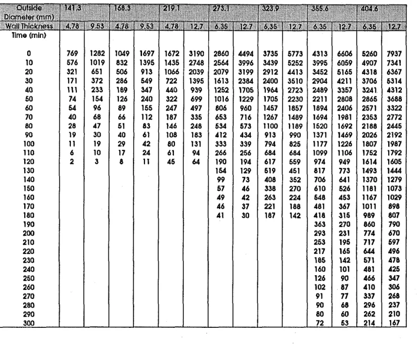
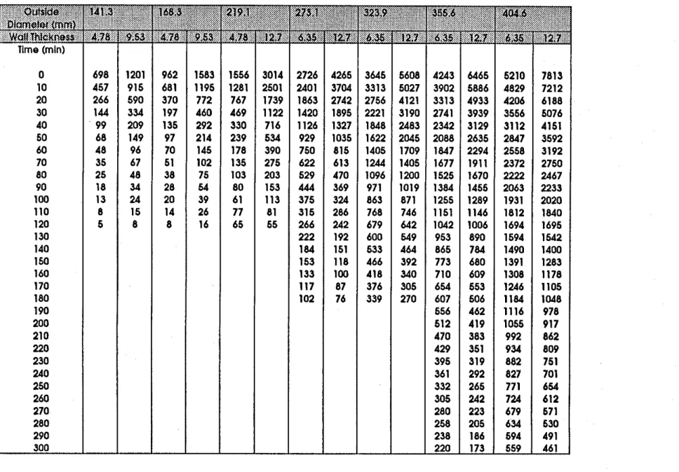
Strength (kN) of SFRC-Filled HSS Column as a Function of Time for Various Steel Outside Diameters and Steel Wall Thicknesses
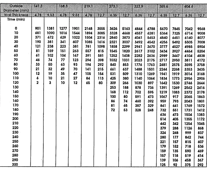
(Effective Length: 2.5m. Concrete Strength: 20 MPa, Aggregate: Siliceous) Strength (kN) of SFRC-Filled HSS Column as a Function of Time
for Various Steel Outside Diameters and Steel Wall Thicknesses
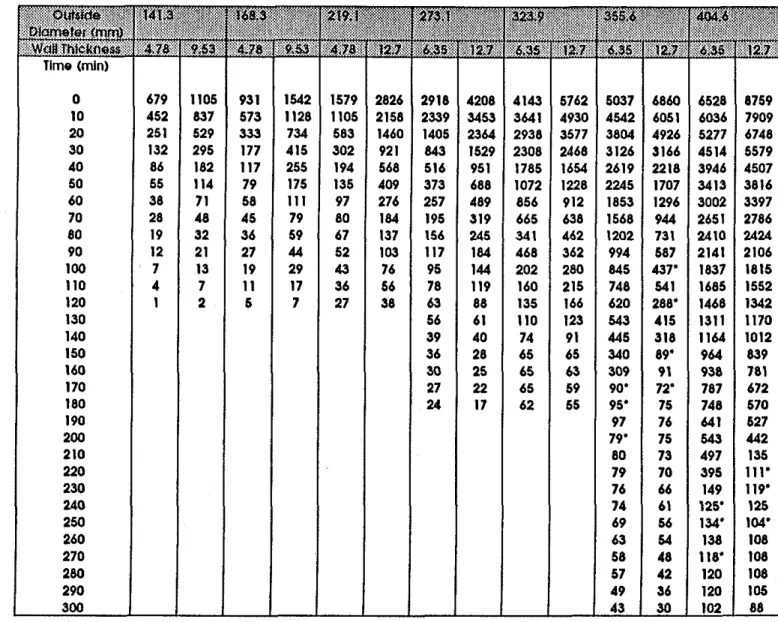
(Effective Length: 25m, Concrete Strength. 35 MPa, Aggregate: Siliceous) Strength (kN) of SFRC-FiUed HSS Column as a Function of T~me for Various Steel Outside Diameters and Steel Wall Thicknesses
(Effective Length: 2.5m, Concrete Strength: 55 MPa, Asregate: Siliceous) Strength (kN) of SFRC-Filled HSS Column as a Function of Time
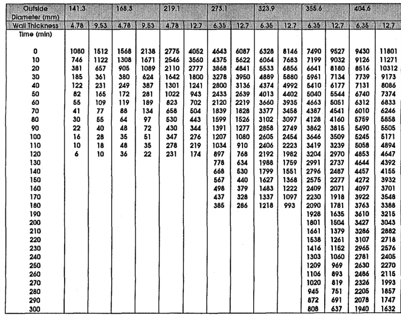
for Various Steel Outside Diameters and Steel Wall Thicknesses
(Effective Length: 3 . h . Concrete Strength: 20 MPa, Aggregate: Siceous) Strength (kN) of SFR-1311ed HSS Column as a E m t i o n of Time
for Various Steel Outside Diameters and Steel Wall Thicknesses
(Effective Length: 3 . h . Concrete Strength: 35 MPa, A~oregate: Siliceous) Strength (kN) of SFRC-FiUed HSS Column as a Function of Time
for Various Steel Outside Diameters and Steel Wall Thicknesses
(Effective Length: 3.0m, Concrete Strength: 55 M E & Aggregate: Siliceous) Strength (liN) of SFRC-FiUed HSS Column as a Function of Time
for Various Steel Outside Diameters and Steel Wall Thicknesses (Effective Length: 4.5m, Concrete Strength: 20 MPa, Aggregate: Sic-) Strength (kN) of SFRC-Filled HSS Column as a Function of T h e for Various Steel Outside Diameters and Steel Wall Thicknesses
(Effective Length: 4.5m, Concrete Strength: 35 MPa, Aggregate: Siliceous) Strength (kN) of SFRC-Filled HSS Column as a Function of Time
for Various Steel Outside Diameters and Steel Wall Thicknesses
Table 10 Table 11 Table 12 Table 13 Table 14 Table 15 Table 16 Table 17 Table 18
Strength (kN) of SFRC-Fied HSS Column as a Function of T i e for Various Steel Outside Diameters and Steel Wall Thicknesses
(Effective Length: 25m, Concrete Strength: 20 ma, Aggregate: Carbonate) Strength
0
of SFRC-Filled HSS Column as a Function of limefor Various Steel Outside Diameters and Steel Wall Thicknesses
(Effective Length: 25m, Concrete Strength: 35 MPa, Aggregate: Carbonate) Strength (kN) of SFRC-Filled HSS Column as a Function of Time
for Various Steel Outside Diameters and Steel Wall Thicknesses
(Effective Length: 2.5m, Concrete Strength: 55 MPa, Aggregate: Carbonate) Strength (kN) of SFRC-Fied HSS Column as a Function of Time
for Various Steel Outside Diameters and Steel Wall Thicknesses
(Effective Lengfh: 3.0m. Concrete Strength: 20 MPa, Aggregate: Carbonate) Strength (kN) of SFRC-Filled HSS Column as a Function of Ttme
for Various Steel Outside Diameters and Steel Wall Thicknesses
(Effective Length: 3 . b , Concrete Strength: 35 MPa, Aggregate: Carbonate) Strength (kN) of SFRC-Filled HSS Column as a Function of Time
for Various Steel Outside Diameters and Steel Wall Thicknesses
(Effective Length: 3 . b . Concrete Strength: 55 MPa, Aggregate: Carbonate) Strength (kN) of SFRC-Filled HSS Column as a Function of Ttme
for Various Steel Outside Diameters and Steel Wall Thicknesses
(Effective Length: 4.5m. Concrete Strength: 20 MPa, Aggregate: Carbonate) Strength (kN) of SFRC-Filled HSS Column as a Function of Time
for Various Steel Outside Diameters and Steel Wall Thicknesses
(Effective Length: 4.5~1, Concrete Strength: 35 MI?% Aggregate: Carbonate) Strength
(W
of SFRC-Fied HSS Column as a Function offor Various Steel Outside Diameters and Steel Wall Thicknesses
Table 1 Strength (kN) of SFRC-filled HSS Column a$ a tunctlon of llme
Table 2 Strength (kN) of SFRC-fllled HSS Column as a functlon of tlme
Table 4 Strength (kN) of SFRC-fllled HSS Column as a functlon of time
Table 8 Strength (kN) of SFRC-fled HSS Column as a funclion of llme
(Effective length = 4.5m. Concrete Strength = 35 MPa. Aggregate = Slllceous)
Table 9 Shenglh (kN) of SFRC-fllled HSS Column as a funcllon of time
(Effective length = 4.5m. Concrete Strength = 55 MPa. Aggregate = Slllceous)
Table 10 Strength (kN) of SFRC-fllled HSS Column as a function of Hme
Table 11 Strength (kN) of SFRC-fllled HSS Column a$ a iuncllon of Ilme
Table 12 Strenglh (kN) of SFRC-tilled HSS Column as a luncllon of tlme
Table 13 Strength (kN) of SFRC-filled HSS Column as a function of time
Table 15 Strength (kN) of SFRC-lllled HSS Column as a luncHon of tlme
(Effeciive length = 3.0m. Concrete Strength = 55 MPa. Aggregate = Carbonate)
Time (rnln)
Table 16 Strength (kN) of SFRC-illled HSS Column as a functlon of tlme
INDEX
OF
FIGURESFigure 1 Flow chart of calculation procedure
Figure 2 Fire resistances as a function of column outside d i e t e r for loads of 310 kN and 1250 kN
Figure 3 Fire resistance
as
a function of wall thickness for various column outside diametersFigure 4 Fire resistance as a function of load for various column outside diameters Figure 5 F i resistance
as
a function of effective length of the column for loads of310 kN and 1250 kN, and concrete strengths of 20 MPa and 35 MPa
Figure 6 F i e resistance
as
a function of concrete strength for loads of 310kN and 1250 kN Figure 7 F i e resistance as a function of load for a siliceous a g p g a t e and a carbonateCALCULATION
OF
CALCULATiON
OF
PROPERTIES MEMBER TEMPERATURES
TRESS-STRAIN CALCULATION
OF
REUTIONS STRAINS AND STRESSES
INCREASE TIME
Figure
1
-
I I I I I 1 1 I-
-
Load: 31 0
kN-
--
Load: 1250
kN-
-
-
-
-
-
-
-
-
-
I 1 I 1 I 1 I 1 I-
0
50
100
150
200
250
300
350
400
450
Outside diameter, mm
Figure
2
Fire resistance as a function of column outside diameter for
loads of 310 kN and 1250
kN
240
200
.;
160
..
a, 0c
g
120
.-
V) a,a:
.-
80
LL40
0
0
2
4
6
8
10
12
14
16
Wall Thickness, mm
I I I I I 1 I OutsideDiameter
-
-
405rnrn-
-
-
----
356mrn-
-
324 rnrn-
-
273 rnrn-
__,
219mrn-
168 rnrn 141 rnrn IFigure 3
Fire resistance as a function of wall thickness for various
column outside diameters
Figure 4
4000
Load,
kN
I 1 I-
.----
Outside diameter: 405 mm
--
Outside diameter: 273 mm
-
-
Outside diameter: 141 mm
-
-
-
-
\
\-
\..
-.
- -
- -
-
-
\- -
-..
I I I-.
-
-
Fire resistance as a function of load for various column
outside diameters
Figure
5
160 140 120 K.-
100-
w 0 K 80 V).-
V)!??
2
60.-
LL 4020
0Fire resistance as a function of effective length of the column
for loads of 31 0
kN
and 1250
kN,
and concrete strengths
of 20 MPa and 35
M
Pa
-
I I I I-
-
-
35 MPa-
-
-
35 MPa-
,
\
-
20 MPa - - z 1\
\\
- -
Load: 310 kN 20Mpa\
'\\
1:-
--
Load: 1250 kN I I I I 0 1 2 34
5Effective length, m
0
0
10
20
30
40
50
60
70
Concrete strength, MPa
.
I 1 I I I 1-
/
1
-
-
-
0 0 --
-
/ /I /-
/-
-
Load: 31 0 kN-
--
-
Load:
1250 kN I I I 1 I IFigure
6
Fire resistance as
a
function of concrete strength for a load
of
310
kN and
a load of
1250
kN
I I I
-
Siliceous
aggregate
-
--
Carbonate aggregate
-
-
-
-
-
-
-
-
-
-
0 1000 2000 3000 4000Load, kN
Figure
7
Fire resistance as a function of load for a siliceous
aggregate and a carbonate aggregate concrete
APPENDIX A: MATERIAL PROPERTIES
AND
SPECIFICS OF COLUMNSAND FURNACE
STEEL PROPERTJES
Stress strain relations
for E, 5 ~p where $ = 4 x 10⁶fF mlm and f ( ~ , 0 . 0 0 1 ) = ( 5 0 - 0 . 0 4 ~ ) x [ l - e x ~ ( ( - 3 0 + 0 . 0 3 ~ ) ~ ~ ) ] x 6.9 (-43) where ~ ( T , ( E $ -E? +0.001))=(50-0.04~)~ ( - 3 0 + 0 . 0 3 T ) J ~ ) ] x 6 . 9 (-45) Thermal capacity for 0°C I T 5 650°C p,c,
=
(0.004T+
3.3) x lo6 J/(m3"c) for 650°C<
T 5 725OC p,c,=
(0.068T-
38.3) x lo6 J/(m3"C) for 725°C < T 1 800°C pw = (-0.086T+
73.35) x lo6 J / ( ~ ~ ~ c ) (-48) for T>
800°C pw=4.55 x lo6 J/(m3"C) Thermal conductivity for O°C 5 T 5 900°Ck,
= -0.022T+
48 Wl(m°C)for T > 900°C
k.4
= 28.2 W/(m°C)Coeflcient of thermal expansion
for T < 1000°C
a, = (0.004T
+
12) x, lo6 m/(m°C) for T 2 1000°Ca,= 16 x lo6 m/(m°C)
STEEL FIBRE-REINFORCED CONCRETE PROPERTIES
Thennal capacity
Siliceous aggregate concrete
for 0 1 T 1 200°C p.c, = (0.005T
+
1.7) x lo6 J/(m3"C) for 200 < T 1 400°C pee, = 2.7 x lo6 J/(m3~c) for 400 < T 1500°C p,c, = (0.013T-
2.5) x lo6 J/(m3"C) for 500 < T 1 600°C p,c, = (-0.013T+
10.5) x lo6 J/(rn3~C) for T > 600°C pee, = 2.7 x lo6 J / ( ~ ~ ~ c ) Carbonate aggregate concretefor 0 1 T 1 400°C p,c, = 2.566 x lo6 J/(m3"C) for 400
<
T 1410°C p,c, = (0.1765T-
68.034) x 10' J / ( ~ ~ ~ c ) for 410 < T 1 445°C p,c, = (-0.05043T+
25.00671) x lo6 J/(m3~C)for 445
<
T 1 500°C p,c, = 2.566 x lo6 J/(m3"c) for 500 < T 1 635OC p,c, = (0.01603T-
5.44881) x lo6 J/(rn3~c) for 635 < T1715'C p , ~ , = (0.16635T-
100.90225) x lo6 J / ( ~ ~ ~ c ) for 715<
T 1785°C p , ~ , = (-0.22103T + 176.07343) x lo6 J / ( ~ ~ ~ c ) for T > 785°C p,c, = 2.566 x lo6 J/(m3"c) Thermal conductivi@Siliceous aggregate concrete
for 0 1 T 1 200°C k = 3.22
-
0.007T W/(m°C) for 200 < T 5 40OoC k = 2.24-
0.0021T W/(m°C) for 400 < T 11000°C k = 1.4 W/(m°C) carbonate aggregate concretefor 0 1 T 5 500°C
k = 2.000 - 0.001775T Wl(m°C) for 500 < T 1 1000°C
k = 1.402 - 0.000579T W/(m°C)
Coeficient of thermal expansion
Siliceous aggregate concrete
for 0 1 T 1530°C
for 530 < T 2 600°C
o = 0.0364 + 0.000083T m/(m°C) for 600 < T I 1000°C
o = 0.0135 m/(m°C) Carbonate aggregate concrete
for 0 2 T 2750°C
o = -0.001 15
+
0.00001T m/(m°C) for 750<
T I 1000°C0 = -0.05 187
+
0.000077T m/(m°C)Stress-strain relations for siliceous and carbonate aggregate concretes
for E, 2 ,,E
for & > ,,&
where E , = 0.003
+
(7.OT + 0 . 0 5 ~ ~ ) x lo6m/m
for T 2 150°Cf,
=f,
[1+0.000769(~-20)] MPa for 150 < T 2 400°C f i = l . l f i MPa for T > 400°C WATER PROPERTIES Thermal capacityHeat of vaporization
SPECIFICS OF COLUMNS
AND
FURNACE&f = emissivity of column furnace fie: 0.75
E, = ernissivity of steel: 0.8
APPENDIX B: NOMENCLATURE Notations
C = load intensitv
Cr = factored compressive resistance of concrete core
Cn: = factored compressive resistance of concrete-filled steel columns c = specific h e a t , ~ / ( k ~ ' ~ )
D = outside diameter of the HSS section f = stress, MPa
f, = concrete stress at ternperature T, MPa
fc = cylinder strength of concrete at temperature T, MPa cylinder strength of concrete at room temperature, MPa strength of steel at temperature T, MPa
thermal conductivity, W/m°C effective length factor
length of column that contributes to axial deformation, m unsupported length of the column, m
mass at temperature T (kg) mass at room temperature (kg) temperature, "C
wall thickness of HSS section
coefficient of thermal expansion, 1I0C
emissivity, strain, mlm
concrete strain at temperature T (m
concrete strain at max. stress of stress-strain curves for temperature T (m el)
heat of vaporization, Jikg density, kg/m3 time, h = concentration of moisture Subscripts c = of concrete f = of fire
max=
maximum 0 = at room temperaturep = pertaining to proportional stress strain relation s = of steel