HAL Id: hal-01571588
https://hal.archives-ouvertes.fr/hal-01571588
Submitted on 19 Jul 2018
HAL is a multi-disciplinary open access archive for the deposit and dissemination of sci-entific research documents, whether they are pub-lished or not. The documents may come from teaching and research institutions in France or abroad, or from public or private research centers.
L’archive ouverte pluridisciplinaire HAL, est destinée au dépôt et à la diffusion de documents scientifiques de niveau recherche, publiés ou non, émanant des établissements d’enseignement et de recherche français ou étrangers, des laboratoires publics ou privés.
Stacked magnetic resonators for MRI RF coils
decoupling
Elodie Georget, Michel Luong, Alexandre Vignaud, Eric Giacomini, Edouard
Chazel, Guillaume Ferrand, Alexis Amadon, Franck Mauconduit, Stefan
Enoch, Gérard Tayeb, et al.
To cite this version:
Elodie Georget, Michel Luong, Alexandre Vignaud, Eric Giacomini, Edouard Chazel, et al.. Stacked magnetic resonators for MRI RF coils decoupling. Journal of Magnetic Resonance, Elsevier, 2017, 275, pp.11-18. �10.1016/j.jmr.2016.11.012�. �hal-01571588�
Passive Magneto-Electric Resonators for MRI RF Coils Decoupling
Elodie Georgeta*, Michel Luongb, Alexandre Vignauda, Eric Giacominia, Edouard Chazela, Guillaume Ferrandb, Alexis Amadona, Franck Mauconduitc, Stefan Enochd, Gérard Tayebd, Nicolas Bonodd, Cyril Poupona, and Redha Abdeddaimd
a
Université Paris-Saclay, CEA-Saclay, DRF/I2BM/Neurospin/UNIRS, 91191 Gif-sur-Yvette Cedex, France.
b
Université Paris-Saclay, CEA-Saclay, DRF/IRFU/SACM, 91191 Gif-sur-Yvette Cedex, France.
c
Siemens Healthcare, 93210 Saint-Denis, France.
d
Aix Marseille Université, CNRS, Centrale Marseille, Institut Fresnel, UMR 7249, 13013 Marseille, France
*Corresponding author
Email adresses: [email protected] (Elodie Georget), [email protected] (Michel Luong), [email protected] (Alexandre Vignaud),
[email protected] (Eric Giacomini), [email protected] (Edouard Chazel), [email protected] (Guillaume Ferrand), [email protected] (Alexis Amadon), [email protected] (Franck Mauconduit), [email protected] (Stefan Enoch), [email protected] (Gérard Tayeb), [email protected] (Nicolas Bonod), [email protected] (Cyril Poupon), [email protected] (Redha Abdeddaim).
Abstract
Parallel transmission is a very promising method to tackle B1 +
field inhomogeneities at ultrahigh field in magnetic resonant imaging (MRI). This technique is however limited by the mutual coupling between the radiating elements. Here we propose to solve this problem by designing a passive magneto-electric resonator that we here refer to as stacked magnetic resonator (SMR). By combining numerical and experimental methodologies, we prove that this passive solution allows an efficient decoupling of active elements of a phased-array coil. We demonstrate the ability of this technique to significantly reduce by more than 10 dB the coupling preserving the quality of images compared to ideally isolated linear resonators on a spherical salty agar gel phantom in a 7 T MRI scanner.
Keywords: high-field RF coils; linear resonator; phased array coil; passive decoupling; metamaterial. 1. Introduction
By increasing the magnetic field strength B0 of MRI
scanners, image quality is appreciably improved, especially for human brain imaging [1]. However, at ultra-high field, the transmitted B1
+
field features inhomogeneities in the human head at the proton Larmor frequency (around 300 MHz for a 7 T MRI). These RF inhomogeneities are due to a shorter wavelength than for usual clinical MRI systems [2, 3]. To counterbalance them, different techniques have been proposed for single-channel transmission: metamaterials coupled with loop coils [4, 5], or high dielectric pads [6, 7] coupled with birdcage coils. Another strategy, especially well adapted to ultra-high field, consists in using a phased array coil instead of the common birdcage coil. Parallel transmission allows to drive several RF transmit elements independently in order to mitigate RF field inhomogeneities [8]. Transmit elements, e.g. loops or linear resonators (stripline or dipole) are fed individually by RF power channels [9]. A Butler matrix [10] or singular value decomposition (SVD) [11] can be used to distribute the RF power from each channel to several transmit elements. To ensure the maximum efficiency, transmit elements are located around the human head, or around a phantom. The higher the number of elements, the smaller the distance between them, and the higher the inter-element coupling. This coupling can decrease the signal-to-noise ratio (SNR). In addition, a high coupling between transmit elements may damage the components of the Tx/Rx circuits and the
network matching circuit of each element of the coil (capacitor, diode). To overcome these limitations, different decoupling techniques have been proposed: overlapping loops [12], induced current compensation or elimination (ICE) with microstrips [13, 14], and reactive decoupling circuits between adjacent elements [15-18]. Recently,
several groups adapted metamaterial decoupling
techniques used for telecommunication antenna to the MRI domain. Two kinds of decoupling structures are used: magnetic walls to decouple loops [19, 20] and electromagnetic band gap structures for dipole coils [21]. In this paper, a passive decoupling method is inspired by a metamaterial structure. This decoupling structure, composed of stacked magnetic resonators (SMR), can decouple linear resonators (LRs) of a parallel transmission RF coil. Although in this manuscript we will consider only transmit coils, the SMR structure may be useful for both transmission and reception. This paper is organized as follows. The first section explains the general setup, the SMR design and its positioning between two adjacent linear resonators (LRs). The section 3 explains the method of our experiment. In section 4, results show the ability of the SMR structure to decouple the LRs of a transmit array coil in terms scattering parameters. Finally, the proof of concept of the transmit array coil with SMR is validated in a 7 Tesla MRI scanner. The results with and without passive decoupling are displayed in terms of measured flip angle and simulated |B1
+
| field maps. The simulation results presented in this paper were obtained with the
transient solver available in the electromagnetic software Microwave Studio, Computer Simulation Technology (Darmstadt, Germany).
2. Experimental Setup
2.1. General Setup
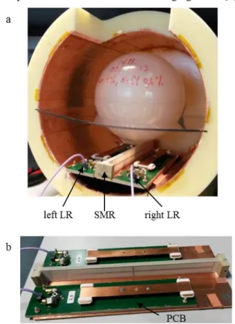
The setup is composed of two LRs in a shielded shell with a spherical phantom (Fig 1.a) and is designed for a 7 Tesla MRI. The shell of the coil is a 25 cm diameter cylinder, with an opening of 10x14 cm² provided for the eyes of the volunteer in functional imaging. The transceiver LR has been previously designed for a complete phased array coil used in parallel transmission for head imaging at 7 T [9].
Fig. 1. (a) Experimental setup with the SMR. (b) Position of the
SMR between the two LRs.
The two LRs are fed by a balun circuit included in the printed circuit board (PCB) and fixed to a copper plate connected to the shielding inside the shell (Fig. 1b). The two LRs are separated by a distance of 7.6 cm (0.08*λ0)
(Fig. 3a). They are capacitor-shunted at their extremities to reduce their length. To tune and match the LRs, a π-matching network is placed at the input of their feeding point. The matching network is composed of two 1.5-19 pF variable capacitors connected to the ground with a 53-71 nH variable inductor between them. This circuit can be seen on top of the PCB on the left of Fig. 1b for each LR. In simulation, the matching circuits are not visible in Fig. 3a. since they have been optimized using the RF circuit tools of the CST software. To mimic the human brain, we used a 15.6 cm diameter spherical phantom filled by an Agar-agar salted gel (r = 74.2, = 0.87 S/m).
2.2. SMR Design
For human head MRI at 7 T, the transmit elements of a phased array coil are usually separated by a distance around a tenth of the wavelength in free space λ0. This
short distance induces a strong coupling between the transmit elements that we propose to decrease with a metamaterial structure that has been designed by capacitive loaded loops (CLL) [22]. The unit structure is made of two CLL in the (x0z) plane, symmetrically placed with respect to the z-axis on a Rogers RO4003C 0.813 mm-thick substrate (cf. Fig. 2a).
Fig. 2. (a) Pattern of one SMR layer. Drawing is not to scale;
dimensions are in mm. Copper path (0.4 mm width, in orange) on substrate (white rectangle). (b) Left axis: RCS of the SMR structure when excited by a plane-wave (PW) with three different orientations. PW1: 𝑘⃗ =k𝑥 , 𝐸⃗ =E𝑧 , 𝐻⃗⃗ =H𝑦 . PW2: 𝑘⃗ =k𝑧 , 𝐸⃗ =E𝑥 , 𝐻⃗⃗ = -H𝑦 . PW3: 𝑘⃗ =-k𝑦 , 𝐸⃗ =E𝑧 , 𝐻⃗⃗ =-H𝑥 . The insert shows the magnetic field distribution on the SMR central layer at 290.4 MHz. Right axis, dotted purple line: directivity of the LR coupled with the SMR as a function of the frequency. (c) 3D directivity pattern of the LR with SMR at 6 different frequencies.
A periodic arrangement of this unit structure has featured good decoupling properties [23]. This planar design of CLL has been adapted to our case by limiting the number of layers due to space limitations in the MRI coil. The more you add layers, the better the decoupling until a number of layers where the best decoupling is reached. In our case, three layers of the unit cell with a period P=2.45 mm are needed for the best decoupling. The relative permittivity of the layer substrate is equal to
r= 3.38 with a dissipation factor tan(δ)= 0.0027. The
dimensions of the SMR structure have been optimized to exhibit the highest gain in directivity at the Larmor
frequency fL (see Figs.2b). To determine the
electromagnetic modes of the SMR structure with three layers, the radar cross section (RCS) is simulated in the frequency range [260-340] MHz with three plane-wave (PW) excitations [24] (Fig. 2b). We note that the SMR structure exhibits a resonance at 290.4 MHz when the magnetic component 𝐻⃗⃗ of the excitation is orthogonal to the SMR structure (PW1 and PW2). The insert in Fig. 2b displays the magnetic field distribution at resonance (290.4 MHz). As expected with scatterers satisfying the Kerker conditions extended to the case of a near field excitation [24], the maximum of directivity of a magneto-electric antenna does not occur at the maximum of the RCS since it results from a coupling between electric and magnetic modes [25]. We can observe in Fig.2b-c that the maximum gain in directivity appears at fL and is associated
with an almost complete suppression of lateral radiation.
2.3. Position of the decoupling structure
Let us now study the magnetic field transmitted by a single LR at the position of its neighboring LR (see insert in Fig. 3b). A single LR above a 200x300 mm² ground plane is simulated (only the right LR in Fig. 3a is present). The amplitudes of the three magnetic field components along the blue line (z-axis) are reported in Fig. 3b. It can be observed that the Hy component has the highest strength, meaning that the decoupling SMR structure must be oriented perpendicular to the y-axis to counteract the main magnetic field component [26].
3. Method
In order to analyze the interactions between the SMR and the emitting LR, the magnetic field distribution at the Larmor frequency is studied in simulation. Moreover, to assess the decoupling efficiency of the SMR, the scattering parameters are measured with and without SMR using a vector network analyzer. The reflection coefficients of both LRs are equivalent since the LRs are close to identical: S11 ≈ S22.
The experimental procedure is as follows. First, each LR is tuned and matched independently at fL in the presence of
the phantom. We call “isolated LR” the configuration where the LR is alone in the shell with the phantom. In the second configuration, the two LRs are located 7.6 cm apart (Fig. 3a). Finally, in the last configuration, the SMR is positioned between the LRs, 1 mm from the lower edge of the SMR substrate above the copper plate (Fig. 1b).
To check the influence of the SMR on the |B1+| field map,
the setup is placed in a Siemens Magnetom 7 T MRI scanner and a B1-field mapping sequence is launched for
each of the 3 configurations. During the image acquisition with two LRs, while one LR transmitted, the other one was loaded with 50 Ohms. So only one LR was transmitting
and receiving during the acquisitions of the flip angle (FA) maps.
Fig. 3. (a) Simulation of two adjacent LRs on a ground plane (b) Components of the simulated magnetic field stemming from
an isolated LR at the location of the second LR, at a height x= 12.3 mm from the ground plane (blue line on the insert).
For each measurement, FA maps are acquired with a 2D magnetization-prepared turbo-FLASH sequence (XFL) [27, 28], averaged over 10 acquisitions to increase SNR. The imaging parameters are: transversal acquisition;
resolution: 4 mm isotropic; field of view:
160x160x160 mm3. The FAs obtained with and without SMR are compared to the isolated LR case on a voxel-by-voxel basis inside the spherical phantom, allowing calculation of the normalized root mean square errors and correlation factors. To evaluate the SMR structure influence on the reception chain noise figure, background noise was measured, calculating its standard deviation from a 1000-voxel cubic box located in the corner of the 3D reconstructed stack of the “reference” XFL images. 4. Results
4.1. S-parameters
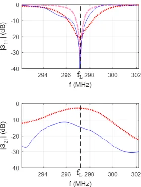
Two LRs with and without SMR were simulated in the shell in the presence of the phantom. Fig. 4 shows the calculated reflection coefficient S11 of the right LR, and
the transmission coefficient S21 between the two LRs. The
measurement results are displayed in Fig. 5 and they agree with the simulated results. Every result is compared to the case of the isolated LR. The isolated LR is well adapted at fL (dashed pink line): |S11| = -34.7 dB in simulation and
Fig. 4. Simulated S-parameters: reflection coefficient S11 of the right LR, and transmission coefficient S21 between the two LRs. Dashed pink line: isolated LR; dotted red line: LRs adapted together without SMR; blue line: LRs with SMR.
Experimentally, when the LRs individually tuned at fL are
positioned at 7.6 cm from each other, a strong coupling occurs (black line in Fig. 5). This coupling is characterized by a splitting of the resonance frequency of the LR with an increase of 29 dB of the reflection coefficient, and a high coupling between the LRs (|S21|= -5.2 dB).
Using the matching circuits of the two LRs, it is possible to reduce this coupling by suppressing the splitting observed on the resonant mode and compensate the mismatch (dotted red line). Indeed, the coupled LR is well matched at fL since we obtain |S11|= -20.0 dB in simulation
and |S11|= -15.6 dB in measurement. Nevertheless, the
coupling between the LRs remains high since |S21| is
higher than -10 dB at fL.
With the presence of SMR between the two LRs (blue line), the matching of the LR is similar to the isolated LR case. Moreover, the transmission coefficient S21 has been
reduced by more than 10 dB with SMR in simulation and measurement: from -2.7 dB without SMR to -14.4 dB with SMR in simulation, and from -6.7 dB to -20 dB in measurement.
4.2. |B1 +
| field maps
The FA maps of the phantom’s central axial slice are acquired with an input power of 200 W. Since the XFL FA-measurement is less and less precise as FA get close to 0° [29], a low threshold on the measured FA has been applied (minimum FA = 15°, which corresponds to a minimum |B1
+
| = 1.86 μT). Nevertheless, some artefacts are still present in areas with a low SNR due to eddy current in the copper plate where the two LRs are positioned.
Fig. 5. Measured S-parameters: reflection coefficient S11 of the right LR, and transmission coefficient S21 between the two LRs. Dashed pink line: isolated LR; black line: LRs adapted individually without SMR; dotted red line: LRs adapted together without SMR; blue line: LRs with SMR.
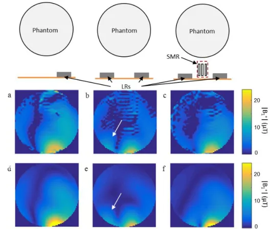
These FA maps are displayed in term of |B1 +
| field in Fig. 6a-c. The simulated |B1
+
| field maps are shown in Fig. 6d-f for an input power of 200 W. The simulated and measured spatial distributions are in good agreement. To compare the field maps, the isolated LR case is taken as the reference. The |B1
+
| field map of this reference is shown in Fig. 6a with the maximum |B1
+
| field at the position facing the right LR. At the position facing the left LR, we note that the |B1
+
| are very low, inferior to 4.4 μT.
The simulated and measured field maps with a single LR differ notably from those when the two LRs are present (Fig. 6b, 6e). Indeed, the LR coupling translates into two spots at the bottom of the phantom, as though there were two transmitters. Note that the coupling globally reduces the |B1
+
| values. Moreover, the |B1 +
| values at the position facing the left LR increase because of the coupling between the two LRs (white arrow in Fig. 6b, 6e). Yet the area where the B1
+
| values are superior to 10 μT is reduced by the coupling, leading to a reduced penetration depth into the phantom.
The measured and simulated |B1 +
| field maps with SMR (Fig. 6c, 6f) are close to those of an isolated LR case. The SMR inserted between the two LRs removes the second spot on the left. Thus, less power is dissipated in the left LR when the right LR is transmitting. The designed SMR can decouple two LRs and allow them to transmit signal just as if they were isolated. The |B1+| field maps of the
central axial slice show that |B1 +
| values are higher in average with SMR than without SMR.
Fig. 6. Field maps of the central axial slice of the right LR: isolated (a,d), without (b, e), and with (c, f) the SMR. Central axial slices
of the measured |B1+| maps with an input power of 200 W (a-c) and CST simulated |B1+| field maps (d-f) with the same input power.
Fig. 7. Scatter plots on the whole phantom volume: measured
|B1+| without (a) and with (b) SMR vs |B1+| of the isolated case; simulated |B1
+
| without (c) and with (d) SMR vs |B1 +
| of the isolated case. Normalized root mean square error NRMSE and correlation factors R indicated above figures.
Fig. 7 shows the comparison of the |B1 +
| obtained with and without SMR to those obtained in the isolated LR case, on a voxel-by-voxel basis inside the spherical phantom.
Fig. 7a shows the results in measurement and Fig. 7b shows the results in simulation. The |B1
+
| smaller than 1.86 μT in measurement are excluded from the comparison. The measured |B1
+
| with SMR is closer to the red line x=y in measurement and simulation. Moreover, the normalized root mean square error decreases by more than 14% and the correlation factor is increased by 13% with SMR in measurement and simulation. This confirms the observations made on the central axial slice. The designed SMR structure enhances the |B1
+
| field maps and approaches the isolated LR case.
The noise in each case is compared as well. Compared to the isolated case, the standard deviation of the noise is increased by 13.7 % when adding the second LR. The addition of the SMR reduces significantly this extra noise down to 1.5 %. We can conclude that the LR with SMR behaves almost like an isolated LR.
5. Conclusion
In this study, a new decoupling method for phased-array RF coils based on a metamaterial solution is investigated. Using the SMR structure between adjacent LRs has several benefits. The transmission coefficient between two LRs decreases from -6.7 dB to -20 dB. The RF field distribution becomes closer to that obtained in the case of an isolated LR. The second spot on the |B1+| field map due
to the coupled LR is eliminated. Moreover, the extra noise induced by the coupling is reduced by an order of magnitude. Thus the LR behaves like an isolated LR thanks to the decoupling structure.
The absence of connection between the SMR structure and the transmit phased-array coil is a decisive advantage of this passive solution. This makes easier the integration of the structure. Moreover, this decoupling structure allows using variable capacitors with lower withstanding voltage on the LRs. This decoupling structure can also decouple the elements of the phased-array coil in receive mode. By decreasing the extra noise due to the coupling, this structure can increase the SNR.
In conclusion, adding SMR structure in transmit-array coils enhances the performances in terms of decoupling, |B1
+
| efficiency and noise. Reducing the coupling between transmit elements will allow implementing RF coils with more elements thus improving the performance of array coils even more. The next step of our study is to implement a complete Tx-array coil with SMR structures in-between adjacent Tx-elements.
Acknowledgments
This work was supported by Conseil Général de l’Essonne, France (ASTRE -2012), France Life Imaging, and CMRI Carnot Star.
References
1. Vaughan JT, Garwood M, Collins CM, et al. 7T vs. 4T: RF power, homogeneity, and signal‐to‐noise comparison in head images. Magn Reson Med 2001;46:24-30. doi: 10.1002/mrm.1156
2. Wald LL, Wiggins GC, Potthast A, Wiggins CJ, Triantafyllou C. Design considerations and coil comparisons for 7 T brain imaging. Applied Magnetic Resonance 2005;29:19-37.
3. Pohmann R, Speck O, Scheffler K. Signal-to-noise ratio and MR tissue parameters in human brain imaging at 3, 7, and 9.4 tesla using current receive coil arrays. Magn Reson Med 2016;75:801-809. doi: 10.1002/mrm.25677.
4. Freire MJ, Marques R, Jelinek L. Experimental demonstration of a μ=− 1 metamaterial lens for magnetic resonance imaging. Applied Physics Letters 2008;93: 231108. doi: 10.1063/1.3043725.
5. Jouvaud C, Abdeddaim R, Larrat B, de Rosny J. Volume coil based on hybridized resonators for magnetic resonance imaging. Applied Physics Letters 2016;108:023503. doi: 10.1063/1.4939784.
6. Teeuwisse WM, Brink WM, Haines KN, Webb AG. Simulations of high permittivity materials for 7 T neuroimaging and evaluation of a new barium titanate‐based dielectric. Magn Reson Med 2012;67:912-918. doi: 10.1002/mrm.24176.
7. Teeuwisse WM, Brink WM, Webb AG. Quantitative assessment of the effects of high‐permittivity pads in 7 Tesla MRI of the brain. Magn Reson Med 2012;67:1285-1293. doi:
8. Cloos MA, Boulant N, Luong M, et al. kT‐points: Short three‐dimensional tailored RF pulses for flip‐angle homogenization over an extended volume. Magn Reson Med 2012;67:72-80. doi: 10.1002/mrm.22978.
9. Georget E, Ferrand G, Luong M, Giacomini E, Chazel E, Hang MF, Bernard J, Poupon C, Amadon A, A transmit-array RF coil with 12 transmit elements and 22 receive elements for an 8-channel parallel transmission system at 7T, 6th Annual Scientific Symposium Ultrahigh Field Magnetic Resonance,
June, 26th, 2015, Berlin.
10. Yazdanbakhsh P, Bitz An Orzada S, Kraff O, Ladd ME, Solbach K. In: Proceedings of the 17th Annual Meeting ISMRM, Honolulu, Hawaii, USA 2009 (p. 3385).
11. Ferrand G, Luong M, Cloos MA et al. SVD-based hardware concept to drive N transmit elements of a phased array coil with M≤N channels for high field MRI. In: Proceedings of the 17th Annual Meeting ISMRM, Honolulu, Hawaii, USA 2009 (p. 3018).
12. Roemer PB, Edelstein WA, Hayes CE, Souza SP, Mueller OM. The NMR phased array. Magn Reson Med 1990;16,192-225. doi: 10.1002/mrm.1910160203.
13. Li Y, Xie Z, Pang Y, Vigneron D, Zhang X. ICE decoupling technique for RF coil array designs. Med Phys 2011; 38:4086-4093. doi: 10.1118/1.3598112.
14. Yan X, Zhang X, Wei L, Xue R. Magnetic wall decoupling method for monopole coil array in ultrahigh field MRI: a feasibility test. Quantitative
imaging in medicine and surgery 2014;4:79-86. doi: 10.3978/j.issn.2223-4292.2014.04.10.
15. Jevtic J, Pikelja V, Menon A, Seeber D, Tatum N, Johnson W. Design guidelines for the capacitive decoupling networks. In: Proceedings of the 11th Annual Meeting ISMRM, Toronto, ON, Canada, 2003 (p. 428). 16. Wu B., Zhang X., Qu P., Shen G. X., Design of an inductively decoupled
microstrip array at 9.4 T. J Magn Reson 2006;182:126-132. doi: 10.1016/j.jmr.2006.04.013.
17. Wu B, Qu P, Wang C, Yuan J, Shen GX. Interconnecting L/C components for decoupling and its application to low‐field open MRI array. Concepts in Magnetic Resonance Part B: Magnetic Resonance Engineering 2007;31:116-126. doi: 10.1002/cmr.b.20087.
18. Avdievich N. I, Pan JW, Hetherington HP. Resonant inductive decoupling (RID) for transceiver arrays to compensate for both reactive and resistive components of the mutual impedance. NMR Biomed 2013;26:1547-1554. doi: 10.1002/nbm.2989.
19. Connell IR, Gilbert KM, Abou-Khousa M, Menon RS. MRI RF Array Decoupling Method With Magnetic Wall Distributed Filters. IEEE Trans Med Imaging 2015;34;825-835. doi:10.1109/TMI.2014.2378695.
20. Connell IR, Gilbert KM, Abou-Khousa M, Menon RS. Design of a Parallel Transmit Head Coil at 7T With Magnetic Wall Distributed Filters. IEEE Trans Med Imaging 2015;34:836-845. doi:10.1109/TMI.2014.2370533. 21. Hurshkainen AA, Derzhavskaya TA, Glybovski SB, et al. Element
Decoupling of 7T Dipole Body Arrays by EBG Metasurface Structures: Experimental Verification. J Magn Reson 2016;269:87-96. doi:10.1016/j.jmr.2016.05.017.
22. Ferrer PJ, González‐Arbesú JM, Romeu J, Cardama A. Bidirectional artificial magnetic reflectors at microwave frequencies. Microwave and Optical Technology Letters 2007;49:1949-1953. doi: 10.1002/mop.22567. 23. Ferrer PJ, González‐Arbesú JM, Romeu J. Decorrelation of two closely
spaced antennas with a metamaterial AMC surface. Microwave and Optical Technology Letters 2008;50:1414-1417. doi: 10.1002/mop.23365.
24. Rolly B., Stout B., and Bonod N., “Boosting the directivity of optical antennas with magnetic and electric dipolar resonant particles,” Opt. Express 2012;20:20376-20386. doi: 10.1364/OE.20.020376
25. Rolly B., Geffrin J.-M., Abdeddaim R., Stout B., Bonod N. Controllable emission of a dipolar source coupled with a magneto-dielectric resonant subwavelength scatterer. Scientific reports 2013;3:3063. doi:10.1038/srep03063.
26. Pendry JB, Holden AJ, Robbins DJ, Stewart WJ. Magnetism from conductors and enhanced nonlinear phenomena. IEEE Trans Microwave Theory and Techniques 1999;11:2075-2084. doi:10.1109/22.798002. 27. Chung S, Kim D, Breton E, Axel L. Rapid B1+ mapping using a
preconditioning RF pulse with TurboFLASH readout. Magn Reson Med 2010;64:439-446. doi: 10.1002/mrm.22423.
28. Amadon A, Mauconduit F, Vignaud A, Boulant N. Slice profile corrections in the XFL (magnetization-prepared turbo-FLASH) B1-mapping sequence. In: Proceedings of the 23th Annual Meeting ISMRM, Toronto, Canada, 2015; (Abstract #2377).
29. Fautz H-P. New Angles on B1 Mapping. Session introduction at the the 18th Annual Meeting ISMRM, Stockholm, Sweden, 2010.