HAL Id: tel-02402859
https://tel.archives-ouvertes.fr/tel-02402859
Submitted on 10 Dec 2019
HAL is a multi-disciplinary open access archive for the deposit and dissemination of sci-entific research documents, whether they are pub-lished or not. The documents may come from teaching and research institutions in France or
L’archive ouverte pluridisciplinaire HAL, est destinée au dépôt et à la diffusion de documents scientifiques de niveau recherche, publiés ou non, émanant des établissements d’enseignement et de recherche français ou étrangers, des laboratoires
Shuai Chen
To cite this version:
Shuai Chen. Investigation of FEM numerical simulation for the process of metal additive manufac-turing in macro scale. Mechanical engineering [physics.class-ph]. Université de Lyon, 2019. English. �NNT : 2019LYSEI048�. �tel-02402859�
N◦d’ordre NNT: 2019LYSEI048
THÈSE de DOCTORAT DE L’UNIVERSITÉ DE LYON
préparée au sein de
l’Institut National des Sciences Appliquées de Lyon
École Doctorale 162
Mécanique, Énergétique, Génie civil, Acoustique
Spécialité/ discipline de doctorat
GÉNIE MÉCANIQUE
Soutenue publiquement le 5 juillet, 2019, par:
Shuai CHEN
Investigation of FEM Numerical Simulation for the
Process of Metal Additive Manufacturing in Macro Scale
Devant le jury composé de:
Jean-Michel BERGHEAU Professeur (ENISE Saint-Etienne) Examinateur
Michel CORET Professeur (Ecole Centrale de Nantes) Rapporteur
Fabrice MORESTIN Professeur (INSA Lyon) Directeur de thèse
Pierre VACHER Professeur (Université Savoie Mont Blanc) Rapporteur
Laurent VAN BELLE Docteur (Centre Technique IPC) Examinateur
Hélène WALTER-LE BERRE Maître de conférences (INSA Lyon) Examinateur
Département FEDORA – INSA Lyon - Ecoles Doctorales – Quinquennal 2016-2020
SIGLE ECOLE DOCTORALE NOM ET COORDONNEES DU RESPONSABLE
CHIMIE CHIMIE DE LYON
http://www.edchimie-lyon.fr
Sec. : Renée EL MELHEM Bât. Blaise PASCAL, 3e étage
INSA : R. GOURDON
M. Stéphane DANIELE
Institut de recherches sur la catalyse et l’environnement de Lyon IRCELYON-UMR 5256
Équipe CDFA
2 Avenue Albert EINSTEIN 69 626 Villeurbanne CEDEX [email protected] E.E.A. ÉLECTRONIQUE, ÉLECTROTECHNIQUE, AUTOMATIQUE http://edeea.ec-lyon.fr Sec. : M.C. HAVGOUDOUKIAN [email protected] M. Gérard SCORLETTI
École Centrale de Lyon
36 Avenue Guy DE COLLONGUE 69 134 Écully
Tél : 04.72.18.60.97 Fax 04.78.43.37.17
E2M2 ÉVOLUTION, ÉCOSYSTÈME, MICROBIOLOGIE, MODÉLISATION
http://e2m2.universite-lyon.fr
Sec. : Sylvie ROBERJOT Bât. Atrium, UCB Lyon 1 Tél : 04.72.44.83.62 INSA : H. CHARLES
M. Philippe NORMAND
UMR 5557 Lab. d’Ecologie Microbienne Université Claude Bernard Lyon 1 Bâtiment Mendel 43, boulevard du 11 Novembre 1918 69 622 Villeurbanne CEDEX [email protected] EDISS INTERDISCIPLINAIRE SCIENCES-SANTÉ http://www.ediss-lyon.fr
Sec. : Sylvie ROBERJOT Bât. Atrium, UCB Lyon 1 Tél : 04.72.44.83.62 INSA : M. LAGARDE
Mme Emmanuelle CANET-SOULAS
INSERM U1060, CarMeN lab, Univ. Lyon 1 Bâtiment IMBL
11 Avenue Jean CAPELLE INSA de Lyon 69 621 Villeurbanne Tél : 04.72.68.49.09 Fax : 04.72.68.49.16 [email protected] INFOMATHS INFORMATIQUE ET MATHÉMATIQUES http://edinfomaths.universite-lyon.fr
Sec. : Renée EL MELHEM Bât. Blaise PASCAL, 3e étage
Tél : 04.72.43.80.46 Fax : 04.72.43.16.87 [email protected] M. Luca ZAMBONI Bât. Braconnier 43 Boulevard du 11 novembre 1918 69 622 Villeurbanne CEDEX Tél : 04.26.23.45.52 [email protected]
Matériaux MATÉRIAUX DE LYON
http://ed34.universite-lyon.fr
Sec. : Marion COMBE
Tél : 04.72.43.71.70 Fax : 04.72.43.87.12 Bât. Direction [email protected] M. Jean-Yves BUFFIÈRE INSA de Lyon MATEIS - Bât. Saint-Exupéry 7 Avenue Jean CAPELLE 69 621 Villeurbanne CEDEX
Tél : 04.72.43.71.70 Fax : 04.72.43.85.28
MEGA MÉCANIQUE, ÉNERGÉTIQUE, GÉNIE CIVIL, ACOUSTIQUE
http://edmega.universite-lyon.fr
Sec. : Marion COMBE
Tél : 04.72.43.71.70 Fax : 04.72.43.87.12 Bât. Direction [email protected] M. Jocelyn BONJOUR INSA de Lyon Laboratoire CETHIL Bâtiment Sadi-Carnot 9, rue de la Physique 69 621 Villeurbanne CEDEX [email protected] ScSo ScSo* http://ed483.univ-lyon2.fr
Sec. : Viviane POLSINELLI Brigitte DUBOIS
INSA : J.Y. TOUSSAINT Tél : 04.78.69.72.76 [email protected] M. Christian MONTES Université Lyon 2 86 Rue Pasteur 69 365 Lyon CEDEX 07 [email protected]
Acknowledges
This thesis is the result of a research work I have carried out between 2015 and 2018 at the Laboratory of Mechanic of Contacts and Structures (LaMCoS), funded by the China Scholarship Council.
I would like to express my gratitude to all those whole helped me during the comple-tion of the thesis. Without their support and encouragement, this thesis could not have reached its present form.
First and foremost, I want to extend my sincere gratitude to Ms. Hélène WALTER-LE BERRE, whose patient guidance, valuable suggestion and constant encouragement make me successfully complete this thesis. She has instructed me through all the stages of the accomplishment of this thesis. Her conscientious academic spirit and modest, open-minded personality inspire me both in academic study and daily life. She gives me much help and advice during the whole process of my research. Our frequent discussions make it possible for me to promote my study in the rapid development of additive manufactur-ing.
Second, I would like to express my heartfelt gratitude to Mr. Fabrice MORESTIN, who do me a great favour in the work of my thesis. He has many innovative ideas about additive manufacturing, and we have exchanged some interesting discussions in this work. His academic insight helped me to discover the value of my research. When I was con-fused during this work, his sagacious advice led me to return to the correct research di-rection.
The reviews and critics from my jury are also of importance for me to improve my the-sis’ quality. I’d like also deliver my thanks for their review work on my thesis manuscript. This thesis was one part of a large project of LaMCoS aiming at metal additive man-ufacturing, which involved multi-disciplinary aspects (macroscopic simulations, micro-scopic melt pool model, and automation, etc.). Mr. Daniel NÉLIAS has also helped me with the proposal of this thesis’s topic at the beginning. Here I’d like to express my thanks to him, too.
Moreover, I would like to express my gratitude to Mr. Ning DANG, a doctor in the laboratory MATEIS. We discussed a lot about the knowledge of metallurgical transfor-mation, which is of great significance for me to complete the multi-physics simulation.
Special thanks for all of my friends that are present in our laboratory: Alexis BONETTO, Chao ZHANG, Deqi LIU, Efoe WALLACE, Lv ZHAO, Meng WANG, Quanshangze DU, Thomas JAILIN, Tristan DJOURACHKOVITCH, Wenfeng YE, Wenjun GAO, Wenqi ZHU, Ye LU, Zikang LOW. During these four years, we enjoyed coffee breaks, lunches and so many other pleasant moments in LaMCoS. They helped me in many different manners, and I hope to continue to see them regularly.
I wish to appreciate all professors who have taught me in INSA de Lyon. Their in-structions have helped broaden my horizon and their enlightening teaching has provided me with a solid foundation to accomplish this thesis and will always be of great value for my future career and academic research.
Last but not least, I would like to deliver my special thanks to my parents, whose supports from more than 8000 kilometres have motivated me to overcome difficulties in study and life during these years.
Abstract
Additive manufacturing (AM) has become a new option for the fabrication of metallic parts in industry. However, there are still some limitations for this application, especially the unfavourable final shape and undesired macroscopic properties of metallic parts built in AM systems. The distortion or crack due to the residual stress of these parts leads usually to severe problems for some kinds of metal AM technology. In an AM system, the final quality of a metallic part depends on many process parameters, which are nor-mally optimized by a series of experiments on AM machines. In order to reduce the considerable time consumption and financial expense of AM experiments, the numerical simulation dedicated to AM process is a prospective alternative for metallic part fabri-cated by additive manufacturing. Because of the multi-scale character in AM process and the complex geometrical structures of parts, most of the academic researches in AM simulation concentrated on the microscopic melting pool. Consequently, the macroscopic simulation for the AM process of a metallic part becomes a current focus in this domain. In this thesis, we first study the pre-processing of AM simulation on Finite Element Method (FEM). The process of additive manufacturing is a multi-physics problem of cou-pled fields (thermal, mechanical, and metallurgical fields). The macroscopic simulation is conducted in two different levels with some special pre-processing work. For the layer level, the reconstruction of 3D model is conducted from the scan path file of AM machine, based on the inverse manipulation of offsetting-clipping algorithm. For the part level, the 3D model from CAD is reconstructed into a voxel-based mesh, which is convenient for a part with complex geometry. The residual stress of a part is analysed under different preheat temperatures and different process parameters. These simulations imply the po-tential technique of reducing residual stress by the optimisation of process parameters, instead of the traditional way by increasing preheat temperature.
Based on the FEM simulation platform above, two simulations at line level are also studied in this thesis, aiming at the relation between the AM process and part’s final quality. These examples demonstrate the feasibility of using macroscopic simulations to improve the quality control during the AM process. In the first task, dataset of heating parameters and residual stress are generated by AM simulation. The correlation between them is studied by using some regression algorithm, such as artificial neural network. In the second task, a PID controller for power-temperature feedback loop is integrated into AM process simulation and the PID auto-tuning is numerically investigated instead of using AM machine. Both of the two tasks show the important role of AM macroscopic process simulation, which may replace or combine with the numerous trial and error of experiments in metal additive manufacturing.
KEYWORDS:
Additive manufacturing, Numerical simulation, Finite element method,Multiphysics, Residual stress, Voxelization, PID controller, Regression, Artificial neural network
Résumé
La fabrication additive (FA) est devenue une nouvelle alternative pour la fabrication des pièces dans l’industrie. Cependant, il existe encore des limites pour ce procédé, en particulier la forme finale défavorable et les propriétés macroscopiques indésirables des pièces métalliques construites dans les systèmes de FA. La distorsion ou la fissure due à la contrainte résiduelle de ces pièces pose généralement de graves problèmes pour cer-tains types de technologie de la FA métallique. Dans un système de FA, la qualité finale d’une pièce métallique dépend de nombreux paramètres de procédé, qui sont normale-ment optimisés par une série d’expériences sur des machines de FA. Afin de réduire la consommation de temps et le coût financier qui sont considérables dans des expériences de FA, la simulation numérique dédiée au procédé de FA est une alternative potentielle pour les pièces métalliques fabriquées par la fabrication additive. En raison du carac-tère multi-échelle des procédés de FA et des structures géométriquement complexes, la plupart des recherches académiques qui travaillent sur la simulation de FA se sont concen-trées sur le bain de fusion microscopique. Par conséquent, la simulation macroscopique pour le procédé de FA d’une pièce métallique devient actuellement une priorité dans ce domaine.
Dans cette thèse, nous étudions d’abord le pré-processing de la simulation de FA par la méthode des éléments finis (FEM). Le procédé de fabrication additive est un phénomène multi-physique des champs couplés (champs thermique, mécanique et métallurgique). La simulation macroscopique est réalisée à deux niveaux différents. Au niveau de la couche, la reconstruction du modèle 3D est effectuée à partir du fichier de chemin de balayage de la machine de FA, basée sur la manipulation inverse de l’algorithme d’offsetting-clipping. Au niveau de la pièce, le modèle 3D de CAO est reconstruit dans un maillage des voxels, ce qui est pratique pour une pièce avec une géométrie complexe. Avec les températures de préchauffage différentes et les paramètres du procédé différents, la contrainte résiduelle d’une pièce est analysée. Ces simulations impliquent la technique potentielle pour réduire la contrainte résiduelle par l’optimisation des paramètres du procédé, au lieu de moyens traditionnels par augmenter la température de préchauffage.
Basées sur la plateforme de simulation de FEM ci-dessus, deux simulations au niveau de ligne sont également étudiées dans cette thèse, visant à la relation entre le procédé de FA et la qualité finale de la pièce. Ces exemples démontrent la possibilité d’utiliser des simulations macroscopiques pour améliorer le contrôle de la qualité pendant le procédé de FA. Dans la première tâche, l’ensemble de données des paramètres de chauffage et la contrainte résiduelle sont générés par la simulation de FA. La corrélation entre eux est étudiée en utilisant des algorithmes de régression, tel que le réseau neuronal artificiel. Dans la deuxième tâche, un contrôleur de PID pour la boucle de rétroaction puissance-température est intégré dans la simulation de procédé de FA et l’auto-réglage de PID est numériquement étudié au lieu d’utiliser la machine de FA. Les deux tâches montrent le rôle important de la simulation de procédé macroscopique de FA, qui peut remplacer ou combiner les nombreuses expériences essai-erreur dans la fabrication additive métallique.
Contents
Contents i
List of Figures v
List of Tables ix
General introduction 1
1 Basic knowledge on additive manufacturing 5
1.1 Fundamentals of additive manufacturing . . . 7
1.1.1 Advantages . . . 7
1.1.2 Limitations . . . 8
1.2 Typical metal additive manufacturing technologies . . . 9
1.2.1 Extrusion-based or sheet-based additive manufacturing . . . 10
1.2.2 Powder-based additive manufacturing . . . 12
1.3 Some problems in metal additive manufacturing . . . 15
1.3.1 Problems for designers before AM manufacturing . . . 15
1.3.2 Problems during AM process . . . 17
1.3.3 Problems after the printing of an AM object . . . 23
1.4 Some typical techniques for the AM simulation . . . 24
1.4.1 Numerical Methods for dynamic AM process . . . 24
1.4.2 Numerical methods for irregular and free boundary condition . . 27
1.5 Novelty of this work . . . 31
1.5.1 Pre-processing for macroscopic simulation . . . 32
1.5.2 Dynamic simulation at different levels . . . 32
1.5.3 Reduction of residual stress at lower preheat temperature . . . 33
1.5.4 Process parameters study and control loop platform . . . 35
2 Theoretical basis for additive manufacturing simulation 37 2.1 Thermal equation for temperature . . . 39
2.1.1 Basic heat equation for additive manufacturing . . . 39
2.2 Mechanical equation for residual stress . . . 43
2.3 Metallurgical phase models in macroscopic scale . . . 45
2.3.2 Diffusional transformation . . . 48
2.4 Conclusion . . . 52
3 Macroscopic AM simulation for multiphysics fields 55 3.1 Workflow of file formats for additive manufacturing process . . . 57
3.2 Pre-processing for 3D model with complex geometry . . . 60
3.2.1 Analysis G-code file and extraction of scan path information . . . 60
3.2.2 Reconstruction of 3D model at layer size: offsetting and clipping 62 3.2.3 Map of sets in orphan FEM mesh and in CAD geometry . . . 67
3.2.4 Reconstruction of 3D model at part size: voxelization . . . 70
3.3 FEM simulation for multi-physics fields . . . 73
3.3.1 Thermal simulation at layer-level . . . 75
3.3.2 Thermal-mechanical-metallurgical simulation at part-level . . . . 84
3.4 Study on AM process parameters for a part’s residual stress . . . 98
3.4.1 Influence of preheat temperature . . . 99
3.4.2 Influence of AM process parameters (Pi, ti) . . . 101
3.5 Conclusion . . . 108
4 Regression between process parameters and residual stress 111 4.1 Influence of multi-parameters on residual stress . . . 113
4.2 A basic thermal-mechanical AM simulation of a zigzag line . . . 115
4.3 Post-processing of AM simulation with regression . . . 120
4.4 Regression implementations . . . 122
4.5 Artificial neural network for regression . . . 123
4.5.1 Fundamentals of back-propagation algorithm . . . 124
4.5.2 Construction of artificial neural network . . . 125
4.5.3 Regression after AM simulations . . . 126
4.6 Conclusion . . . 128
5 Simulation for the control of the process in additive manufacturing 131 5.1 Preparation for the study of AM thermal system’s control . . . 133
5.2 PID controller in feedback loop . . . 139
5.3 AM simulation with PID power controller for temperature . . . 142
5.4 PID parameters tuning . . . 143
5.4.1 Manual PID tuning . . . 143
5.4.2 Auto-tuning . . . 143
5.5 Conclusion . . . 149
General conclusions and perspectives 151
A Additive manufacturing’s workflow in industry 155
Contents
C Reconstruction of tracks in one layer from G-code 161
D Script for simulating a feedback loop 167
E Subroutines for simulating Ti6Al4V phase transformation 169 F Abaqus post-process program to extract von Mises stress 175
List of Figures
1 Overall structure of this thesis . . . 4
1.1 Bound Metal Deposition[MET 17] . . . 11
1.2 Laminated Object Manufacturing[MEK 16] . . . 12
1.3 Selective Laser Melting(SLM)[YAS 18] . . . 13
1.4 Interaction of laser-material in Selective Laser Sintering (SLS)[KOL 17] . 13 1.5 Electron Beam Melting (EBM)[QUR 18] . . . 14
1.6 Laser deposition device (DMD)[THO 15] . . . 15
1.7 Design of a part’s support structure in additive manufacturing[WRI 15] . 16 1.8 Different printing qualities varying with part’s orientation[WAR 16] . . . 17
1.9 Variation of the residual stress of different types along a line[WIT 01] . . 18
1.10 Crack caused by residual stress[COM 17] . . . 19
1.11 Two mechanisms of residual stress [WIT 07] . . . 19
1.12 A beam’s wrapage induced by residual stress [FRU 15] . . . 20
1.13 Recoater tolerance[AUT 18] . . . 20
1.14 Blade crash of a part’s shape in additive manufacturing[MCG 17] . . . 21
1.15 A part with optimal orientation suffers less from recoater blade interfer-ence effect[ZEL 15] . . . 22
1.16 Incompleted parts induced by lack of fusion[MCG 17] . . . 22
1.17 Balling effect on part’s surface in EBM, caused by overheating[ZÄH 10] . 23 1.18 Wrapping of substrate after AM fabrication[ZEL 15] . . . 24
1.19 Difficulty in the removal of support structure without damage[STA 17] . . 24
1.20 Thermal simulation with DEM for powder-bed AM system. [STE 16a] . . 26
1.21 Computational domain with different mesh densities[STA 18] . . . 27
1.22 Dynamic mesh refinement preparing for heat affected zone[PAT 15] . . . 27
1.23 A scoliosis-brace-model reconstructed by voxelization[FRA 17] . . . 28
1.24 Interfaces tracked by the level set method[ZHA 18] . . . 29
1.25 Simulation results for keyhole and melt pool formation by volume of fluid[OTT 10] . . . 30
1.26 Concept of finite cell method [TAG 18] . . . 30
1.27 Difficulty of connecting AM machine data with FEM simulation . . . 31
1.28 Material deposition at line level[FAL 11] . . . 33
1.29 Different levels for birth and death method . . . 33
1.31 Preheating hardware for powder-injection based techniques[BRA 16] . . 35
1.32 Hardware for the temperature closed-loop of an AM machine[FAR 16] . . 36
2.1 Interactions between multiphysics processes in additive manufacturing . . 39
2.2 Moving free boundary during material deposition . . . 41
2.3 Laser profiles of different TEM[MOR 17] . . . 42
2.4 Goldak heat source model[GOL 84] . . . 42
2.5 Volumetric heat source model . . . 43
2.6 Temperature-induced martensitic transformation[VAN 13] . . . 46
2.7 Basic algorithm for calculating fα0 . . . 47
2.8 Kinetic parameters k(T ) at n = 2.5for diffusional transformation[AHN 16] 48 2.9 Generalization of the Johnson-Mehl-Avrami equation for non-isothermal transformations [CRE 11] . . . 49
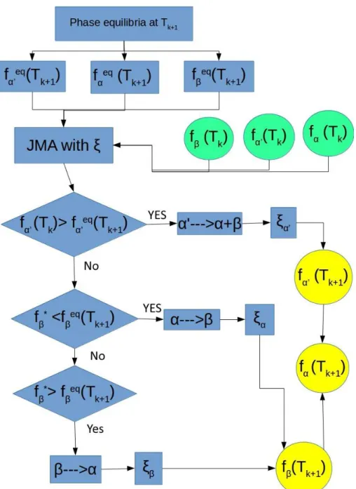
2.10 Algorithm flow chart for diffusional transformation with modified JMA model . . . 52
3.1 Basic workflow in additive manufacturing[TAU 13] . . . 57
3.2 File format conversion from CAD to FEM analysis . . . 58
3.3 A part with complex geometry in slicer software(CuraEngine) . . . 59
3.4 G-code generated by CuraEngine . . . 61
3.5 Reconstruction of a 3D thin-wall structure . . . 63
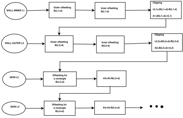
3.6 Inner offsetting of a polygon[CHE 05] . . . 63
3.7 Clipping for a rectangle[HSI 95] . . . 63
3.8 Generation scan path in one layer, (a) is the background paths before clip-ping (b) is the final path [DIN 15a] . . . 65
3.9 Flowchart for partitions in one layer, opposite to slicer’s manipulation . . 65
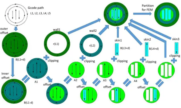
3.10 Generation of the partition for FEM simulation from gcode scan paths . . 66
3.11 Detailed view of one layer in a thin wall during the pre-process . . . 67
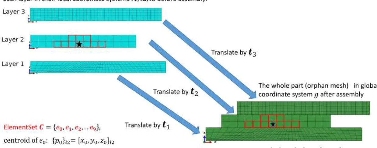
3.12 Loss of ElementSet definition during assembly between different coordi-nates . . . 68
3.13 Flowchart of the algorithm to map ElementSet between two coordinates . 69 3.14 File format conversion in voxelization . . . 71
3.15 3D model of a turbine blade with a twist in vertical direction . . . 72
3.16 Approximation of a blade by voxelization (length of voxel is 1.333mm) . 72 3.17 Geometrical approximation of voxelization . . . 73
3.18 Basic steps of AM simulation using birth and death technique . . . 75
3.19 The first 4 layers of a wall structure (red, yellow, blue, green) . . . 75
3.20 The scan path partition for the 4th layer . . . 76
3.21 The mesh of 4 layers and their substrate. . . 76
3.22 Mechanical property of Maraging steel at different temperatures[VAN 13] 77 3.23 Screenshots of the AM deposition process (546 lines in total, 4 layers), the temperature unit is◦C . . . 82
List of Figures
3.25 Temperature evolution at 4 sensor points . . . 84
3.26 Mesh of the turbine blade (partition of 30 layers) and its substrate . . . . 85
3.27 Ti6Al4V’s material properties which depend on temperature . . . 87
3.28 Mechanical boundary condition at the substrate’s bottom face . . . 88
3.29 Position of 30 sensor points in each layers of the blade . . . 88
3.30 Screenshots of thermal simulation (◦C) in part-level for a blade . . . 90
3.31 Temperature evolution at 30 sensor points . . . 90
3.32 Simple example of substrate effect . . . 91
3.33 Fraction of each layer’s volume Viin whole part Vall. . . 92
3.34 Decoupling of three multi-physics field in this thesis. . . 92
3.35 Screenshots of the simulation for α phase during AM process . . . 93
3.36 Screenshots of the simulation for β phase during AM process . . . 94
3.37 Screenshots of the simulation for martensite α0during AM process . . . . 94
3.38 α phase’s evaluation at 30 sensor points . . . 95
3.39 β phase evaluation’s at 30 sensor points . . . 95
3.40 Evolution of temperature rate dT/dt at 30 sensor points . . . 96
3.41 Final displacement (mm) at environment temperature . . . 97
3.42 Final von Mises residual stress (MPa) at environment temperature with different views . . . 98
3.43 Temperature evaluation of the case in which the preheat temperature Tpre is 500◦C. . . 99
3.44 Final residual stress (MPa) with different preheat temperature Tpre= 500◦C and Tpre= 240◦C(Reference case)(Other AM process parameters are the same) . . . 100
3.45 The input power and heating time for different AM simulation cases. . . . 102
3.46 The coefficient Cifor the input power of the case D. . . 102
3.47 Temperature evolution at 30 sensor points for different simulation cases (Each different colour represents one layer.) . . . 103
3.48 The AM thermal process of Case Ref and Case D. . . 104
3.49 Residual stress σvonMises (MPa) distribution for different simulation cases 104 3.50 Histogram of σvonMises throughout the blade for different simulation cases 105 3.51 PDF of AM case with different preheat temperature Tpre = 500◦C and Tpre= 240◦C(Reference case). . . 106
3.52 PDF of AM cases (Case D and Reference Case). . . 107
3.53 PDF of AM cases (Case A,Case B, Case C and Reference Case). . . 107
4.1 Quality control in powder bed fusion[SAM 16] . . . 113
4.2 Influence of process parameters on the final quality of a part in additive manufacturing . . . 114
4.3 Detailed view of the zigzag track’s mesh . . . 115
4.4 A zigzag track and its substrate . . . 116
4.5 Mesh and mechanical boundary condition . . . 116 4.6 Screenshots of thermal simulation (◦C) for a zigzag track in AM process . 118
4.7 Residual stress (Pa) as tensor components . . . 119
4.8 Residual stress σvonMises (Pa) for a zigzag track line . . . 120
4.9 PDF of the uniform distribution U[0.1, 10.0] . . . 121
4.10 Basic structure of an artificial neuron . . . 123
4.11 Artificial neural network with multiple neurons and layers . . . 125
4.12 Regression using artificial neural network in Tensorflow . . . 127
4.13 Regression using different algorithms in Scikit-learn . . . 128
5.1 Powder-injection based AM system (LENS)[GU 15] . . . 133
5.2 Influence of process parameters (Heat source control) on the quality of component made by AM[VAN 13] . . . 134
5.3 Whole field (multiple points)’s control depends on scan path for an AM system . . . 135
5.4 Difference in temporal respond between LTI system and non-LTI system . 136 5.5 Block diagram of an open-loop AM system . . . 136
5.6 5 simulations for the open-loop AM system . . . 137
5.7 The difference of crowdedness for two deposits . . . 138
5.8 Block diagram of PID controller’s internal structure . . . 140
5.9 Block diagram of a close-loop AM system with a PID controller . . . 140
5.10 Flow chart of PID controller’s algorithm . . . 141
5.11 Relay method for auto-tuning [WIL 05] . . . 144
5.12 Flow chart of relay method for a PID controller’s auto-tuning . . . 145
5.13 Block diagram of a close-loop with relay method for PID auto-tuning . . 146
5.14 Relay method, Ppreset = 6.0 × 10¹¹W/m3, Tpreset = 1600◦C . . . 147
5.15 PID control in AM simulation with different controllers . . . 148
List of Tables
1.1 Catalogue of some AM technologies . . . 9
1.2 Some commerical AM machines and their preheat temperature . . . 34
3.1 Some G-code keywords in CuraEngine . . . 61
3.2 Material property and process parameters in simulation . . . 78
3.3 Ti6Al4V’s material parameters and AM process parameters . . . 86
3.4 Johnson-Cook plastic properties for Ti6Al4V[ZHA 15] . . . 86
3.5 Some cases for AM process parameters adjustment . . . 101
3.6 Statistic results and Burr XII coefficients . . . 106
4.1 Steel parameters and some process parameters . . . 117
4.2 The input parameters and output criteria in 1 time of AM simulation . . . 121
5.1 Ziegler-Nichols auto-tuning method for PID controller . . . 144
General introduction
Additive manufacturing (AM) is becoming more and more important in the fabrication of parts in industry [MIL 17] and it has become a multi-disciplinary hot spot for academic researchers during the last decade. For these metallic part built by additive manufacturing, their qualities aren’t always satisfactory[THO 15]. In metal additive manufacturing, both the shape and property of a part are impacted by AM process, and some problems may limit the application of metallic part made by AM[MOY 13][YAN 17b], such as resid-ual stress, dimensional accuracy, surface qresid-uality, mechanical properties, porosity/density, and fatigue, etc. These problems are generally studied by experiments and numerical simulations. The simulation of AM process provides an important mean to "virtually" run experiments. It is more cost-effective and less time-consuming relative to trial-and-error experimentation with difficult measurement techniques. Now researchers need AM macroscopic simulation as a more convenient tool to discover new techniques for some typical problems in additive manufacturing, such as reduction of residual stress (The older technique by increasing preheat temperature has physics limit). Although numerical sim-ulation has many advantages in AM research, there are still some challenges to solve:• Multi-scale modelling for AM process
The process of additive manufacturing is a multi-physics problem from micro-scale (melting pool) to macro-scale (track, layer, part). The separation of these scales makes it quite difficult to describe the complex phenomena in the AM process as a unique model[KIN 15][GHO 18]. In AM macroscopic simulation, the free surface boundary conditions is an unavoidable problem for the material addition and multi-track deposition effects of 3D objects.
• Geometric irregularity
The pre-processing is often a challenge for AM simulation in macro scale. This is one of the reasons why the majority of AM simulation focused on the thin wall or single line building process [MUK 17] [MIC 14][MAR 14][LIO 15]. The work-flow of additive manufacturing from CAD to CAM, is established on knowledge of computer graphics [LIV 17]. Currently, most CAD software is based on parametric NURBS system. They are well suited to modelling geometries associated with con-ventional manufacturing processes (extrusions, revolves,lofts, etc.) but often inad-equate for the more complex geometrical shapes. Moreover, it isn’t easy to acquire multi-scale geometrical models (melting pool, track line, layer, part, etc.) from a 3D
object in traditional CAD software[THO 16]. Additionally, the scan path generated by slicer algorithms [STE 16b] can’t be directly imported into FEM analysis. Be-cause of the geometric irregularity of an object built by AM, it is necessary to apply special algorithms to reconstruct the 3D model in additive manufacturing[BAD 18]. • Control loop
In an open-loop AM system, fluctuations in the process parameters (e.g., laser power, scanning speed, and powder flow rate) often deflect the process from the poptimized condition, resulting in defects in the finished components. Some re-searchers have developed sensing and control system for the robotically controlled AM systems[MAN 15][SHA 15]. The process monitoring offers a way to ensure part quality and process efficiency. Nevertheless, these real-time systems are still in their infancy[DIN 16d][EVE 16], because they rely on not only hardware but also the understanding of the responsive behaviours of AM systems to process parame-ters.
• Process parameter optimization
The quality of an AM-fabricated component exhibit high dependence on input pro-cess parameters. By appropriately selecting the optimum parameter values, the quality of a part fabricated by AM machine can be improved. It is generally hard to obtain the explicit formulation between process parameters and quality criteria, due to the complexity of AM process. However, the real-time feedback control loop in an AM system relies strongly on the rapid calculation of correlation between input parameters and output parameters. Thus this correlation should be acquired before the start of AM process. The method to reveal phenomenological correlation from datasets of experiments or simulations will be helpful for the quality control in additive manufacturing.
• Ecosystem of AM simulation tools
The additive manufacturing is a rapidly developing area. Many companies adopt the sale strategy of machine-material-software, which makes metal additive man-ufacturing’s ecosystem quite complex [GAO 15]. It isn’t always easy to convert different file formats in the workflow of AM simulation. The majority of in-house or commercial software are close-source. Academic researchers often need more flexible tool to study the detail of simulation detail. Thus it is essential to con-struct numerical platforms based on general-purpose FEM software and explore the methodology of AM simulation.
In this thesis, we investigate the macroscopic AM process of a metallic part by FEM simulation, mainly around the problems above. Here is the structure of this thesis:
In Chapter 1, the current situation of additive manufacturing is introduced, as well as its problems in the application of metallic part fabrication. Some trends in numerical simulation for additive manufacturing are also briefly introduced. The classification of
General introduction
additive manufacturing is various according to different aspects. The mainstream of metal additive manufacture is generally powder-bed based or powder-injection based. For a metallic part fabricated on AM systems, its shape and properties may not be satisfactory as designed. Some numerical methods are applied for the macroscopic simulation of additive manufacturing by academic researchers and proprietary software. The novelty of this thesis is also summarized at the end of this chapter
In Chapter 2, additive manufacturing is mathematically described as a multi-physics coupling problem. The macroscopic behaviours of a building part and its substrate are decoupled into three aspects: thermal field, mechanical field, and metallurgical field. Heat source models are introduced in thermal analysis besides basic governing equa-tion. Elasto-plastic equations are combined with Johnson-Cook hardening model so as to calculate residual stress. For the evolution of metallurgical phases, we take titanium al-loy Ti6Al4V as an example and two-phase transformation models, Koistinen-Marburger (KM) model and modified Johnson-Mehl-Avrami (JMA) model, are briefly introduced.
In Chapter 3, the special problems on pre-processing are investigated for the AM simulation on different levels: layer level and part level. We construct the platform for macroscopic FEM simulation by using polygon offsetting/clipping algorithm and vox-elization method. Because of numerous repeated operations in AM FEM simulation, these pre-processing work are completed by programming instead of manual manipula-tion. In layer level simulation, text-processing on G-code file and coordinates transfor-mation on database are accomplished, which overcome some obstacles of simulating an object with complex geometry. Then the thermal field of 4 thin layers is simulated during their dynamic AM process. Additionally, we use voxelization representation as an ap-proximation of the object created by boundary representation (B-Rep), then voxelization is proved to be a convenient method for part level’s simulation of additive manufactur-ing. Multi-physics fields are simulated for a twisted turbine blade’s printing process. Its residual stress is analysed with different preheat temperature or with different process pa-rameters. This implies a new potential technique to reduce residual stress at lower preheat temperature.
In Chapter 4, some regression analysis is conducted to reveal the statistic relation be-tween AM process parameters and the final quality of the product made by additive manu-facturing. Artificial neural network and other algorithms are compared as post-processing for data acquired from AM macroscopic simulation. The maximum residual stress of part is chosen as the criterion of the product’s final quality while three parameters (deposi-tion order, heat source power and heating time) represents the intricate process in additive manufacturing. With some regression tools, we attempt to obtain the phenomenological relation which estimates quantitatively the influence of these three process parameters on residual stress.
In Chapter 5, the evolution of temperature in an AM thermal field is simulated to demonstrate the feasibility of simulating the feedback control loop in additive manufac-turing. The one-point temperature control is the fundamental framework for AM process control-loop. PID controller and its parameter auto-tuning are investigated by iterations of calculating and post-processing. Regulation of heat source power is conducted so as
to control part’s maximum temperature. A PID controller is integrated into AM simula-tion in which the temperature’s sampling is employed by post-processing work. Ziegler-Nichols method and relay method are adopted, aiming to improving the efficiency of PID controller’s auto-tuning.
General conclusions and perspectives of this work will be given at the end of this manuscript.
Chapter 1
Basic knowledge on additive
manufacturing
This chapter presents the current situation of additive manufacturing, and its problems in the application of metallic
part fabrication. Some trends in numerical simulation for additive manufacturing are also briefly introduced. The
1.1.1 Advantages . . . 7 1.1.2 Limitations . . . 8 1.2 Typical metal additive manufacturing technologies . . . 9 1.2.1 Extrusion-based or sheet-based additive manufacturing . . . 10 1.2.2 Powder-based additive manufacturing . . . 12 1.3 Some problems in metal additive manufacturing . . . 15 1.3.1 Problems for designers before AM manufacturing . . . 15 1.3.2 Problems during AM process . . . 17 1.3.3 Problems after the printing of an AM object . . . 23 1.4 Some typical techniques for the AM simulation . . . 24 1.4.1 Numerical Methods for dynamic AM process . . . 24 1.4.2 Numerical methods for irregular and free boundary condition . . . 27 1.5 Novelty of this work . . . 31 1.5.1 Pre-processing for macroscopic simulation . . . 32 1.5.2 Dynamic simulation at different levels . . . 32 1.5.3 Reduction of residual stress at lower preheat temperature . . . 33 1.5.4 Process parameters study and control loop platform . . . 35
Fundamentals of additive manufacturing
1.1
Fundamentals of additive manufacturing
Additive manufacturing (AM), also known as 3D printing, is the general term for those technologies that create digitally 3D physical objects by successive addition of material. In additive manufacturing, a 3D object is usually built from a digital model into its de-signed shape using layer by layer process. In comparison with formative (eg. casting, forging, mould or dies, plastic injection) or subtractive (e.g. carving, milling, drilling, grinding) manufacturing, additive manufacturing is fundamentally different in method-ologies and it can significantly simplify the process of producing complex 3D objects. Nowadays, Additive manufacturing technologies have already been used for various ap-plications in the engineering industry as well as other areas of society, such as medicine, education, architecture, entertainment, jewellery, and so on[TOF 18].
All AM machines presently use a layer-based approach, in which each layer is a thin cross-section of the part derived from the original Computer Aided Design (CAD) data[ONS 18]. The final part made by AM technology can be considered as a geometri-cal approximation of the originally designed data. The additive manufacturing is broadly applicable in different material categories, including metals, ceramics, polymers, compos-ites and biological materials. Correspondingly, additive manufacturing applies different technologies for the material joining process. Hence, the categories of additive man-ufacturing technologies are still increasing with the rapid development of AM in both industrial and academic research.
1.1.1
Advantages
Additive manufacturing provides many opportunities to design and improve products. Since the first stereolithography fabrication system in the 1980s, additive manufacturing has been revolutionizing the way things are made for more than 30 years. The product portfolio and product life-cycle, such as design (CAD), engineering (CAE), manufac-turing (CAM) and manufacmanufac-turing operations management (MOM), will benefit from the advantages of AM technologies including:
1. Geometrical complexity
Weight is an important parameter in automotive industry and aeronautic industry, cor-relating to fuel consumption. Additive manufacturing’s flexibility in highly complex ge-ometries gives the designer more freedom during the design process to optimize the prod-uct. The lightweight design of parts can be developed with less manufacturing constraints after topology optimization.
2. Less assembly
In additive manufacturing, detailing screw holes and assembly drawing is greatly re-duced by combining features into single-piece part [CUE 18]. Therefore, AM technology is an alternative option for solving geometric dimensioning and tolerancing (GD&T) is-sues in assembly.
in comparison with subtractive manufacturing the required material can be signifi-cantly reduced in additive manufacturing. The use of material can be minimised while part’s strength/weight ratio is still retained after optimization.
4. Highly customizable On-demand production
With the help of AM, manufacturers can increase the diversity of product offerings which are currently too small to specialize due to costs of mould, die or tooling. With a more affordable price, the consumer can buy built-to-order products more closely suitable for individual needs and wants. Without the need for moulds and dies, AM enables the engineers or designer to try multiple iterations simultaneously with less costs. It is also the reason why AM is also sometimes named as Rapid Prototyping.
1.1.2
Limitations
Additive manufacturing has distinct advantages and disadvantages. Thus AM is not al-ways the best choice for all kinds of products. Before the application of additive manu-facturing, designers and engineers should take the trade-off into consideration between its benefits and its limitations. Some limitations restrict the application of AM technology and overcoming these problems is still challenging for scientists and researchers. These limitations are partially summarized as follow:
1. Poor mechanical property and excessive distortion
Due to the layer-by-layer fabrication process, usually some properties of a part is non-isotropic. Therefore, parts made by some AM technologies, especially metallic parts, are often weaker in strength and endurance than their traditionally manufacturing counter-parts. Distortion may occur in the AM process and this may lead to the bad quality of shape, even to the cease of fabricating process.
2. Hardware expense
As opposed to conventional manufacturing machine, additive manufacturing is rela-tively more expensive for large production runs. Specialized equipment, such as devices of high-voltage power supply, are essential for some AM machines. Some auxiliary mod-ules should be installed as well. For example, large numbers of ultra-fine powder or some hazardous volatile organic compounds may be emitted during printing. The de-vices treating harmful emission are indispensable in these AM systems. The integration of sophisticated devices makes the price of AM machines still expensive for industrial application.
3. Limited component size and slow build rate
Many AM machines lay down material in small building chambers and it assures printing resolution with nozzles or other delicate deposition devices. The limited volume of AM system and the speed of material deposition often makes additive manufacturing less competitive in part size and building rate than conventional manufacturing.
4. Difficult process configuration and control
AM machine works digitally from CAD file to its final part. It involves many process parameters impacting the final quality of product. The configuration and control is usually empirical on AM machines. If one factor is changed in AM, the other parameter should be
Typical metal additive manufacturing technologies
re-determined after a series of trial. This is one reason why some AM machine companies often sell their machine bundled with their special raw material. The configuration and control of these parameters during process relies on a better understanding of AM systems and improvement of hardware.
1.2
Typical metal additive manufacturing technologies
The range of materials usable for AM technologies is very wide. Parts can be printed from different plastics like Nylon, polystyrene to metals (steel, titanium, aluminium or other alloys). Today there are so many kinds of materials in AM systems, and even the same kinds of material can be treated by different forming methods in additive manufacturing [CHU 14]. It is quite hard to categorize AM technologies into logical groups. Here is only a brief summary of current additive manufacturing, based on three aspects: material chemical composition, material initial state, and technological method. Since the devel-opment of AM technologies is fast in recent decades and inventions of new systems are still continued in industrial and academic domain, the categorization of AM technologies only includes here some relatively mature technologies.
Table 1.1: Catalogue of some AM technologies
Technology Material Phase Heat
Selective Laser Melting(SLM) metal powder laser
Selective Laser Sintering(SLS) plastics, ceramics powder laser
Electron Beam Melting(EBM) metal powder electron
Laser Engineered Net Shaping /Directed Light Fab-rication /Laser solid Forming /Laser Metal Deposi-tion(LENS/DLF/LSF/LMD)
metal powder laser
Wire Arc Additive Manufacture(WAAM)[DIN 15b] metal wire arc welding
Electromagnetic-Compressed Plasma Deposition Manu-facturing(EPDM)
metal powder plasma
Shaped Metal Deposition(SMD) metal wire TIG welding
Direct Metal Deposition(DMD) metal powder laser
Uniform Droplet Spray/Net Droplet-Based Manufactur-ing(UDS/NDM)
metal droplet induction coil
Electron Beam Freeform Fabrication (EBF3) metal wire electron
Laminated Object Manufacturing(LOM) metal,non-metal laminate heated roller
Laser Cladding(LC) metal,non-metal powder/wire laser
Different AM technologies can be distinguished by the material chemical composi-tion including paper, polymers, wax, resins, metals, ceramics and the mixture of them [IAN 15]. Extensive knowledge of material is necessary for an appropriate choice of forming methods.
Metal is one of the essential materials widely used in current AM systems. Met-als have generally higher yield strength among conventional structural materiMet-als. Their
applications for AM systems are widely researched as its important role in industry, archi-tecture, jewellery and bio-medicine, etc. Nevertheless, for some metal AM systems based on melting or sintering, heat process such as sintering during manufacturing will cause rapid temperature gradients and residual stress or cracking occurs. Nowadays, metal AM technologies have still some severe problems in comparison to conventional subtractive metal manufacturing. Laser and electron beam are usually be used as heat source in metal AM system.
A final workpiece fabricated by additive manufacturing is usually a solidified object. However, the joining process of material depends on the different initial states of raw material in different AM systems [MEL 14]. Powder materials are usually used for metal printing. Powder material can be processed by partially or fully melting and fusing to-gether, creating a solid part with "powder bed fusion" or "directed energy deposition" technologies. Laser or electron beam can be used to melt the powder. Also, the powder can be glued by a special substance called binder. The physics properties of discrete metal powder and a solidified metal sample are generally different because of their difference in scales.
In the development of AM technologies, patents have significant influence on the technical solution. During the validity of one patent, relevant companies often work on similar basic AM systems with certain specific improvement. which makes the nomen-clature of AM technologies quite ambiguous and confusing. Different companies often name their AM system with different names to apply for patents, however, the fundamen-tals of their approaches often have certain similarities. Here we need to review briefly commercialized AM technologies neglecting details in differences between AM compa-nies and trademarks. Different metal additive manufacturing technologies are introduced following.
1.2.1
Extrusion-based or sheet-based additive manufacturing
Some metal additive manufacturing technologies use the metal material whose initial state is semi-liquid or solid sheet. These materials at macro scale are often adopted by some low-cost AM metal systems. In comparison with these powder-based AM technologies (vacuum or inert gas are needed for active micro powder), these macroscopic material require less in terms of working environment.
Bound Metal Deposition
Bound Metal Deposition is an extrusion-based metal additive manufacture technology[NIC 18][BOS 18]. In this AM technology (see Figure 1.1), metal compo-nents are constructed by extrusion of a powder-filled thermoplastic media. Bound metal rods (metal powder held together by wax and polymer binder) are heated and extruded onto the build plate, shaping a part layer-by-layer. The printer of Bound Metal Depo-sition is similar to a printer of FDM (Fused DepoDepo-sition Modelling [MEL 14]) with two extruders. Two different materials are deposited by extrusion, called bound metal rods and ceramic interface media rods. These two materials are fed from the cartridges into the ex-truder, heated to soften the binder, then dispensed through the nozzle. The part and its
Typical metal additive manufacturing technologies
supports are printed using bound metal rods, however, the interface layers between them are printed using ceramic interface media rods. The printed part is placed in the debinder where most of binder can be removed by chemical dissolution. Since the bound metal rod is a mixture of metal and binder. After the process of debinder, An open-pore structure is created in the printed part. Then the part will be sent into sintering furnace like the process of the metal injection moulding (MIM) technology. The part is heated at sintering temperature. Remaining binder is vaporized and metal particles fuse together. During the densification of metal, the interface layer printed between the part and its supports doesn’t bond to metal since this interface is printed of ceramic. This design of separation makes it easy to remove parts from their supports after sintering. In this FDM-like technology, the controlling of shrinkage due to sintering is critical to guarantee the geometrical accuracy of metal part.
Figure 1.1: Bound Metal Deposition[MET 17]
Laminated Object Manufacturing
Laminated Object Manufacturing (LOM) is an AM technology where the part cross-section is laminated sequentially. In this technology[MEK 16], the metal sheet with thin thickness is precisely cut to the shape of one layer by laser cutting tool, then this layer is bonded to the previous layer. Combining subtractive/additive manufacturing, this layer stacking and bonding process enables the relative quick and cheap printing of part. In LOM technology, the bonding between layers can be activated by solid-state diffusion (see Figure 1.2) at high temperature or by ultrasonic welding.
Figure 1.2: Laminated Object Manufacturing[MEK 16]
1.2.2
Powder-based additive manufacturing
In this thesis, we concentrate mainly on the AM technologies dedicating to the fabrication of metallic part. Special attention is paid here to metal additive manufacturing technolo-gies. Currently, most of popular metal AM systems in industry are based on powder-bed or powder-injection.
Powder-bed based technologies
Selective Laser Sintering (SLS) and Selective Laser Melting(SLM) are two kinds of powder-based AM technology[SON 15][WAH 16]. The equipment of SLM and SLS are similar, while the normal materials used in these two systems are different [HEJ 17]: SLM works generally with metal, such as stainless steel, aluminium and titanium alloys. SLS works usually with plastics, glass, ceramics and so on. In these kinds of systems, a thin layer of heat-fusible powder is deposited onto the part-building chamber. Laser device and optics scanning mirror are installed above powder bed in the vacuum or inert-gas filled chamber. The powder is held in a cartridge which might be pre-heated by infra-red. The build platform moves downwards by one layer thickness after one layer of a part is built. Then the new powder layer will be spread uniformly and precisely onto the previous powder bed by a levelling roller or a blade. After the deposition of new powder layer, the zone of cross-section of layers is melted or is sintered selectively by the heat of laser. In SLS/SLM system, the support of part is not necessary since the powder bed can support newly built cross-section layer. The post-process is quite important for these technologies, the whole part must be cool down slowly to avoid warping and curling.
Typical metal additive manufacturing technologies
Figure 1.3: Selective Laser Melting(SLM)[YAS 18]
In SLM, powder is melted and the material consolidates in a welding pool. This different feature makes the final part made by SLM has less porosity than that made by SLS, as the powder is heated below its melting point in SLS. In SLS, solid is formed by the fusion between material particles (sintering). For both systems of SLM and SLS, the control of laser energy input is of significance for the quality of part[VAI 15]. The parts made by SLM/SLS often require stress relieving and annealing to reduce internal residual stress.
Figure 1.4: Interaction of laser-material in Selective Laser Sintering (SLS)[KOL 17]
The electron beam melting (EBM) is an AM technology similar to SLS/SLM [ZÄH 10]. The EBM (see Figure 1.5) uses electron beam as heat source instead of laser in
SLS/SLM. Only materials with high electrical conductivity can be used in EBM technol-ogy. In EBM system, electron beam is focused by deflection coil surrounding the beam. The movement of electron beam’s focus is driven magnetically instead of the mirror gal-vanometers in SLS/SLM. Because of the different mechanisms between the interaction of material/electron beam and that of material/laser, usually EBM is much more efficient in terms of energy absorptivity.
Figure 1.5: Electron Beam Melting (EBM)[QUR 18]
Compared to SLS/SLM system, parts made by EBM technology generally have less precision, worse surface resolution and bigger grain sizes. However, EBM has advantages in less cost and faster scan speed. This makes EBM an important technology in metal additive manufacturing.
Powder-injection based technologies
Direct Metal Deposition (DMD) is a typical powder-jet based AM technology [LAB 17]. This technology can be used not only to manufacture new parts, but also to repair/ rebuild worn or damaged components and to apply wear- and corrosion-resistant coatings [AHS 11]. In DMD system (see Figure 5.1), the metal powder is injected from the coaxial nozzle (see Figure 1.6) into a molten pool, which is created by heat source (usually laser). The powder nozzle moves with the laser beam back and forth, then leaves a track of solidified material. Shield inert gas is also fed with the sprayed metal powder stream. The DMD printer head (nozzles of powder/inert gas, laser beam) is usually inte-grated into CNC/robotic system. With some feedback sensors for melt pool, DMD can be controlled by a closed loop to maintain the quality of a part.
Some problems in metal additive manufacturing
Figure 1.6: Laser deposition device (DMD)[THO 15]
The DMD involves complicated interactions between the laser beam, metal powders, the substrate, and processing gases. The physical phenomena in DMD include laser-powder-melt pool interactions, heat transfer, fusion, fluid flow, and solidification. Com-pared with powder bed based AM technologies, the printing speed of DMD is faster with higher roughness and DMD allows building or repairing larger parts.
DMD technology isn’t only applied in additive manufacturing of new parts, but also in refurnishing-repairing of damaged parts.
Laser Engineered Net Shaping (LENS) and laser cladding are powder-injection based AM technology similar to DMD technology[MAH 14], because they are different patents issued to companies or individuals.
1.3
Some problems in metal additive manufacturing
In industrial application of metal additive manufacturing, the quality of a metallic part isn’t always satisfactory as its design, in terms of both geometrical shape and properties. Some severe problems in macro scale may even lead to the cease of fabrication. Here are some typical macroscopic problems in metal additive manufacturing. Solutions for these issues are still being studied by researchers with experiments or simulations
1.3.1
Problems for designers before AM manufacturing
Before the printing process of additive manufacturing, designers and engineer should consider some problems as follow:
Figure 1.7: Design of a part’s support structure in additive manufacturing[WRI 15]
In the stage of AM design, not only the workpiece’s 3D geometry should be designed in CAD software, but also its support structure should be generated and optimized manu-ally or automaticmanu-ally in some special AM software. The support structure (see Figure 1.7) plays a significant role in the quality of final part[HU 15][JÄR 14]. Generally, two func-tions of support structure should be considered in AM modelling of 3D geometry. Me-chanical supports help prevent overhangs from deformation from gravity or growth stress. Thermal supports allow applied energy a conductive path away from the melt surface, so as to optimize the temperature field distribution [COO 18]. In practice, the maximum overhang angle is an important parameter before the generation of support structure, in-cluding internal support, external support. In support design, the minimization of contact surface between workpiece and its support should also be considered, aiming to reduce the difficulty of support removal in post-processing [DAS 17].
2. Part orientation optimization
Optimization of part’s orientation is an important task in file preparation stage of the AM process chain to achieve better quality product[DAS 15]. In AM pre-process soft-ware, the part’s geometry can be rotated around the axes of AM machine’s coordinate system. The determination of the final orientation in the AM build space depends on sev-eral trade-off actors, thus this is a multi-objective optimization where the designer has to decide the priority among different objectives.
Some problems in metal additive manufacturing
Figure 1.8: Different printing qualities varying with part’s orientation[WAR 16] Common objective functions to optimize the part orientation selection are to improve surface finish (reduce roughness and the risk of wrapping), increase part strength in a specific direction, reduce support volume, minimize build time and maximizing part geo-metric accuracy[TAU 13].
In AM systems, the orthogonal shape is produced almost continuous while the part production in build direction is discontinuous in discrete steps of one layer thickness. Most of parts built by AM technologies have inherently anisotropic properties, usually their strengths are much weaker in Z direction (building direction ) than the XY direction [CAR 15]. Due to the staircase effect caused by adjacent layers, an appropriate orientation of part will eliminate dimensional inaccuracy and is helpful to attain the desired surface finish of workpiece.
1.3.2
Problems during AM process
In the stage of producing a part by AM technology, we should always monitor the property and shape of this part, since the AM part’s quality isn’t always satisfactory.
1. Distortion and crack caused by residual stress
Residual stress is the stress that remains inside a material, when it has reached equi-librium with its environment. Residual stress is generally classified according to the scale (see Figure 1.9) at which they occur[EVE 18]. The type I residual stress (macroscopic ho-mogeneous residual stress) vary over several crystal grains. The type I residual stress can lead to part’s large deformations. The type II residual stress (microscopic homogeneous residual stress) are introduced by different phases in the material. The type III residual stress (microscopic heterogeneous residual stress) occurs due to dislocations at atomic scale. The measurement resolution of most test methods is not precise enough to measure
type II and type III residual stress. Moreover, they are of less importance for the macro-scopic quality of part. Thus most of investigation for part’s scale consider principally the type I residual stress.
Figure 1.9: Variation of the residual stress of different types along a line[WIT 01]
Residual stress is not always disadvantageous, for example, in the produce of tem-pered glass, annealed glass plates are rapidly cooled by forced air. This procedure can introduce compressive stress in the surface area of the plate, thus increasing the overall loading resistance and preventing crack growth at the surface. However, in most cases, residual stress is harmful to the quality of workpiece, since they result in deformations from the intended shape [RAD 92]. Moreover, tensile pre-stress will be added to the stress caused by external loads, thus reducing the strength of the parts and favouring propagation of cracks from the surface.
The metal part’s AM processes, especially these powder-based AM systems, can in-troduce large amounts of residual stress, due to the large thermal gradients which are present inherently in the frequent heating-cooling cycles. It is one of the major issues for the additive manufacturing of metallic parts and it will negatively impact the mechan-ical properties of the final part [YAD 15] [VAN 16]. The residual stress leads to part’s distortion (see Figure 1.12) or crack (see Figure 1.10) during building process and the premature failure during use.
Some problems in metal additive manufacturing
Figure 1.10: Crack caused by residual stress[COM 17]
When molten metal is deposited on a cold underlying layer, the thermal contraction of the solidified material occurring during solidification creates tensile stress in the de-posit and compression stress in the underlying layer. Since this dede-position is repeated frequently in AM process, the residual stress of final part can reach a remarkable level.
Two mechanisms can be distinguished which cause residual stress (see Figure 1.11). The first mechanism introducing residual stress is the temperature gradient mechanism. The second mechanism is the cooling of molten top layers mechanism[WIT 07][VOR 17].
Figure 1.11: Two mechanisms of residual stress [WIT 07]
The temperature gradient mechanism explains the generation of residual stress in heating step [MER 06]. It results from the large thermal gradients that happen around the spot of laser or electron beam. Because of the rapid heating of the upper deposit in AM process and the rather slow heat conduction, a steep temperature gradient devel-ops. When material is deposited on a cold underlying layer, this newly deposited heated layer’s expansion is restricted by its underlying layer, then elastic compressive strains are induced[CAS 11]. When the material’s yield strength is reached, the top layer will be plastically compressed[VOR 17]. In the absence of mechanical constraints, a counter bending away from the heat source would be perceived. During the cooling, the plasti-cally compressed upper layers start shrinking and a bending angle towards the laser beam develops. In fact, even the material isn’t molten yet in heat step, the residual stress can occur just because of the different behaviours of thermal expansion between layers.
The cooling of molten top layers mechanism can explain the residual stress induced in the cooling step. In the cooling step, The molten top tends to shrink due to the thermal
contraction[CAS 11]. This deformation is inhibited again by the underlying solidified layers, thus introducing tensile stress in the added top layer and compressive stress in the underlying layers[VOR 17].
Figure 1.12: A beam’s wrapage induced by residual stress [FRU 15]
In additive manufacturing of metallic part, the local temperature at the spot of heat source is very high and the material bears rapid heating and cooling cycle. These features make it complex to foreseen the residual stress in parts made by AM systems. Control-ling of detrimental residual stress and reducing its magnitude to a manageable level are inevitable tasks for most of AM technologies dedicating to metallic part. In practice, some heat treatments are executed as post-process of stress relief for the fabricated workpiece. When excessive distortion or shrinkage due to residual stress can be predicted, the initial geometry file of workpiece can be modified and some compensation design can be added before the AM building process so as to improve part’s final quality
2. Recoater interference (blade crash)
For the AM technologies based on powder bed system, one of the factors that im-pacts quality is the recoater. Recoater is a device in powder delivery system of power-bed based AM machine, which is able to spread the powder in a homogeneous way. Before the construction of one layer, it spreads the powder from one side of the build platform to the other, then the new powder layer is prepared with accurate thickness. Accord-ing to the material of blade, two kinds of recoaters are used in powder-bed based AM machines[AUT 18]. The soft recoater’s blade is made from silicon, rubber or soft carbon fibre (for instance a brush recoater). The hard recoater’s blade is made of steel or ceramic.
Some problems in metal additive manufacturing
Because of its flexibility, the soft recoater can give way slightly in case of a collision with any metal parts being built[MCG 17]. The hard recoater, in comparison with the soft recoaters, exerts pressure on the powder and doesn’t allow much part deformation. This also means that when the hard recoater collides with a part, the build stops or some of your models are dragged across the powder bed [MOY 13][LIO 14]. In order to mea-sure the interference of recoater blade on the powder layer previously deposited, recoater clearance is configured in powder-bed based AM system. Recoater clearance is the per-centage of the next powder layer that is not impinged upon by the upward deflection of the component[AUT 18], as is shown in Figure 1.13. A low recoater clearance leads po-tentially to the damage of newly built layers (see Figure 1.14)or the recoater blade itself.
Figure 1.14: Blade crash of a part’s shape in additive manufacturing[MCG 17]
In practice, designers need to optimise the part’s orientation (see Figure 1.15) before the fabrication using additive manufacturing, depending on experience from trial-and-error.
Figure 1.15: A part with optimal orientation suffers less from recoater blade interference effect[ZEL 15]
3. Lack of fusion or overheating
The quality of workpiece depends on the temperature control in AM process. Delam-ination, swelling and excess porosity are the unfavourable phenomena caused by inaccu-rate energy input control [TAN 17].
Due to incomplete melting of powder or insufficient re-melting of the underlying solid, delamination may occur and it may lead to interlayer cracking. A lack of layer adherence may also induce delamination when the temperature of the material isn’t high enough to reach its melt temperature.
Figure 1.16: Incompleted parts induced by lack of fusion[MCG 17]
If the material is overheated, the melted material may solidify into spheres instead of solid layers. In macroscopic scale, the materials humps above the underlying layer and the swelling happens. In fact, these are caused by the surface tension effect in the melt pool at excessive temperature.
Some problems in metal additive manufacturing
Figure 1.17: Balling effect on part’s surface in EBM, caused by overheating[ZÄH 10]
It is still hard to control precisely the input power in AM building process as the reaction between the material and heat source is quite complex. For parts with excessive porosity, isostatic pressing (HIP) is often used as densification post-processing of AM systems, especially those based on sintering.
1.3.3
Problems after the printing of an AM object
After the end of AM process, there are still some problems should be taken into consid-eration.
Removal/cutting of the part from substrate
In an AM machine, metal workpieces are usually built on a substrate with which the first layer forms ductile interface. As a consequence, the part’s removal from its substrate is necessary during post-processing. Additionally, the substrate, a plate usually made of metal, is also affected by the heating process in additive manufacturing (see Figure 1.18). It may warp and cause the distortion of workpiece’s geometry. This wrapping may result in permanent plastic deformation [PRA 15]. The distortion will be more severe when the materials of workpiece and its substrate have different thermal expansion coefficient. In practice, the substrate is often pre-heated before the deposition of the first layer. More-over, skilful operations are often needed for a part with complex support structure like the object in Figure 1.19.
Figure 1.18: Wrapping of substrate after AM fabrication[ZEL 15]
Figure 1.19: Difficulty in the removal of support structure without damage[STA 17]
1.4
Some typical techniques for the AM simulation
Investigations of the problems in metal additive manufacturing usually depend on lots of expensive/extensive experiments. Additionally, measuring the evolution of multi-physics fields during AM process is often restricted by hardware limitation. Numerical simula-tions, especially these macroscopic simulations for the AM process, provide an important alternative of for engineers and researchers[MIN 15]. Because of the complexity of AM process, this simulation often apply some special method to resolve the multi-scale and multi-physics problem. Here are some brief introductions for the trends of AM simula-tions.
1.4.1
Numerical Methods for dynamic AM process
In the dynamic process in additive manufacturing, the metal material is deposited on its substrate or its previous layer one chunk by one chunk. All of these complex phe-nomenon (stacking of material, moving heat source, interaction of new melt powder/so-lidified metal, etc.), require some special numerical method for AM process simulation. 1. Birth and death technique in FEM
![Figure 1.15: A part with optimal orientation suffers less from recoater blade interference effect[ZEL 15]](https://thumb-eu.123doks.com/thumbv2/123doknet/14690389.745238/43.892.255.635.166.484/figure-optimal-orientation-suffers-recoater-blade-interference-effect.webp)
![Figure 1.17: Balling effect on part’s surface in EBM, caused by overheating[ZÄH 10]](https://thumb-eu.123doks.com/thumbv2/123doknet/14690389.745238/44.892.255.634.171.431/figure-balling-effect-surface-ebm-caused-overheating-zäh.webp)
![Figure 1.20: Thermal simulation with DEM for powder-bed AM system. [STE 16a]](https://thumb-eu.123doks.com/thumbv2/123doknet/14690389.745238/47.892.145.759.227.479/figure-thermal-simulation-dem-powder-bed-ste-a.webp)
![Figure 1.32: Hardware for the temperature closed-loop of an AM machine[FAR 16]](https://thumb-eu.123doks.com/thumbv2/123doknet/14690389.745238/57.892.194.687.189.488/figure-hardware-temperature-closed-loop-machine-far.webp)
![Figure 2.9: Generalization of the Johnson-Mehl-Avrami equation for non-isothermal transformations [CRE 11]](https://thumb-eu.123doks.com/thumbv2/123doknet/14690389.745238/70.892.149.762.407.928/figure-generalization-johnson-mehl-avrami-equation-isothermal-transformations.webp)