HAL Id: tel-01418983
https://tel.archives-ouvertes.fr/tel-01418983
Submitted on 18 Dec 2016
HAL is a multi-disciplinary open access archive for the deposit and dissemination of sci-entific research documents, whether they are pub-lished or not. The documents may come from teaching and research institutions in France or abroad, or from public or private research centers.
L’archive ouverte pluridisciplinaire HAL, est destinée au dépôt et à la diffusion de documents scientifiques de niveau recherche, publiés ou non, émanant des établissements d’enseignement et de recherche français ou étrangers, des laboratoires publics ou privés.
Sari Lakkis
To cite this version:
Sari Lakkis. New Gas Sensor for Exhaust Emissions of Internal Combustion Engines.
Op-tics [physics.opOp-tics]. Université de Versailles-Saint Quentin en Yvelines, 2014. English. �NNT :
Ecole Doctorale Sciences et Technologies de Versailles, N° 539
Pour l’obtention du grade de
Docteur de l’Université de Versailles Saint Quentin en Yvelines
New Gas Sensor for Exhaust Emissions of
Internal Combustion Engine
Présenté par :
Sari Lakkis
Spécialité : Electrique, Electronique, Photonique et Systèmes Le 17 Décembre 2014
Devant le Jury composé de :
M. Patrick Meyrueis, Professeur, Université de Strasbourg, Président M. Frederic Magoules, Professeur à l’Ecole Centrale de Paris , Rapporteur M. Karim Djouani, Professeur à l'Université de Paris XII , Rapporteur
Mme Fadila Maroteaux, Professeur à l'Université de Versailles Saint Quentin, Examinatrice M. Yasser Alayli, Professeur à l'Université de Versailles Saint Quentin, Directeur de thèse M. Rafic Younes, Professeur à l'Université Libanaise, Co-Directeur de thèse
2
Abstract
Gases represent one of the most important key measurands in many industrial and domestic activities. One of the most important applications of gas sensing is in the concentration measurement of exhaust emissions in internal combustion engines. The variety of gases emitted by these engines and the necessity for a precise measurement of their concentrations are the major incentives for researchers to develop gas sensors that are not only limited to a certain type of gases but to a variety of gases. The most interest gases include CO, NO, NO2, NH4, SO2, CO2, CH4 and other hydrocarbons. These gases can be harmful to human health if present beyond a certain concentration.
The analysis of exhaust emissions of internal combustion engines has traditionally been achieved in laboratories using bulk gas analyzers and costly equipments. In order to create a system which can do the work of these analyzers, a sensor that can measure the concentration of multiple gases at the same time is needed. Instead of using a sensor for each gas which is costly and introduce another complexity to the analysis procedure due to the different technologies that are used in the detection of different types of gases. This directly translates into loss of financial and human resources that could otherwise be productively used. In an effort to remedy this situation, this dissertation proposes an alternate approach that uses one sensor to analyze multiple gases simultaneously. This has a significant potential in reducing the aforementioned complexity, size and data collection tasks, and at the same time can lower the cost of the overall system.
This dissertation presents the design, methodology, and development of a new method for gas concentration measurement using digital image processing through modeling the color mixing of light emissions in gas discharge tube. The application of the inverse model allows us to get the percentages of each gas in a mixture of up to four gases knowing already the color of emission of the whole mixture and the color of emission of each gas alone. It also discusses the miniaturization potential of some of the methods that are promising in the ability of their miniaturization but suffer from different problems. A comparison is also done among the miniaturized sensors in terms of different parameters like sensitivity, selectivity, cost and other terms.
In achieving the research objectives, major technical challenges such as color mixing modeling, imaging sensor calibration, and measurements’ error handling have been successfully identified and addressed.
3
Résumé
Dans plusieurs applications industrielles et domestiques, les gaz sont des éléments de mesure importants. L’une entre elles est la mesure de la concentration des gaz d'échappement des moteurs à combustion interne. La variété des gaz émis par ces moteurs et la nécessité d'une mesure précise de leurs concentrations sont les principales motivations des chercheurs quant au développement de capteurs à gaz. Ces derniers peuvent détecter un ou plusieurs types de gaz tels que CO, NO, NO2, NH4, SO2, CO2, CH4 et d'autres hydrocarbures, car ils sont nocifs pour la santé humaineau-delà d'une certaine concentration.
L’analyse des gaz d’échappement des moteurs à combustion interne a été traditionnellement réalisée en laboratoires en utilisant des analyseurs de gaz en vrac avec des équipements coûteux. Afin de créer un système capable de réaliser le travail de ces analyseurs, un capteur pouvant détecter plusieurs gaz simultanément est indispensable pour en mesurer la concentration. En effet, utiliser un capteur pour chaque gaz est couteux et peut amener à des procédures complexes d’analyse en raison des différentes technologies utilisées. De plus, l’utilisation de multiples capteurs donne lieu à une perte de ressources financières et humaines. Pour pallier ce problème, une approche alternative proposée dans cette thèse consiste à utiliser un seul capteur pour l’analyse simultanée des différents gaz. Cette approche contribue à réduire la complexité des analyses, la taille et la collecte de données des mesures de gaz mentionnés précédemment. Elle permet également la baissedu coût de l’ensemble du système des mesures.
Cette thèse présente la conception, la méthodologie et le développement d’une nouvelle approche pour la mesure de la concentration de gaz utilisant le traitement d’images numériques à travers la modélisation du mélange des couleurs d’émission de lumière dans le tube de décharge de gaz. L’application du modèle inverse permet d’obtenir le pourcentage de chaque gaz dans un mélange contenant jusqu'à quatre gaz connaissant la couleur d’émission du mélange et la couleur d’émission de chaque gaz. Nous discutons aussi le potentiel de certaines méthodes quant à leurs propriétés de miniaturisation et leurs limites. Une comparaison entre les différents capteurs miniaturisés est réalisée en termes suivant la sensibilité, la sélectivité, le coût et d’autres conditions. Pour atteindre les objectifs de recherche, les problèmes techniques rencontrés tels que la modélisation de mélange des couleurs, l’étalonnage de capteurs pour l’acquisition d’images, et le traitement des erreurs de mesures ont été identifiés et des solutions ont été proposées.
4 To My Family
And
5
Acknowledgments
During my PhD study, I had the privilege to work with Professor Yasser Alayli who was my supervisor at UVSQ. During this period, he has been extremely helpful. I would like to take this opportunity to specially thank him for his sincere support. I really appreciate his every effort and help to achieve the objectives of the presented work. I would also like to appreciate the support of co-supervisor Professor Rafic Younes who was my teacher and also my supervisor at the Faculty of Engineering in the Lebanese university. I am grateful for his guidance, advices and suggestions to improve the quality of my work. His deep insight and advice improved the quality of this research and provided me with the necessary boost that helped accomplish the work in a timely manner. Also Special thanks to the other members of my Ph.D. committee, Professors Frederic Magoules, Karim Djouani, Mustapha Ouladssine, and Fadila Maroteaux for their contributions to the presented work, and for providing me with invaluable advice and deep insight and suggestions. I would like also to mention Professor Mazen Ghandour at the Lebanese University for his contributions to the presented work, and for providing me with invaluable advices. I am also grateful to Professor Mohamad Sawan at the Ecole Polytechnique of Montreal for his confidence in and support of my research.
I would like to express my great appreciation to my wonderful parents, my aunt, my brother, and my sister, who have always been a major source of motivation and support for me in every minute of my life. I strongly believe if it were not for their encouragements and persevering endeavor, I could not achieve any progress in my life, education, and career. My special thanks go to my friend Dr. Sawsan Kanj, who was a constant support for me to accomplish this thesis.
I am very thankful to all my friends, especially Ali Hallal, Marwa El-Hajj, Ghada Beydoun, and Kassem abudeed for their sincere friendship and help during the past years.
6
Table of Contents
Dedication………...……2 Acknowledgments……….….3 List of Figures……….….…..7 List of Tables………..9 Abstract……….10 Chapter 1. INTRODUCTION ... 151.1 IMPORTANCE OF THE RESEARCH ACTIVITY ... 16
1.2 APPLICATIONS OF GAS SENSORS ... 17
1.3 PRIOR STATE OF KNOWLEDGE ... 18
1.4 RESEARCH OBJECTIVES ... 20
1.5 RESEARCH METHODOLOGY ... 21
1.6 DISSERTATION OUTLINE ... 22
1.7 REFERENCES ... 23
2. REVIEW OF RECENT TRENDS IN GAS SENSING TECHNOLOGIES AND THEIR MINIATURIZATION POTENTIAL 25 2.1 INTRODUCTION ... 25
2.2 STATE OF THE ART ... 25
2.3 CONDUCTING POLYMER GAS SENSORS ... 26
2.3.1 Conducting Polymer Chemiresistor Gas Sensors ... 26
2.3.2 Conducting Polymer Transistor and Diode Gas Sensors... 27
2.4 PIEZOELECTRIC CRYSTAL GAS SENSORS ... 28
2.5 CARBON NANOTUBES (CNTS)BASED GAS SENSORS. ... 32
2.6 OPTICAL GAS SENSORS ... 34
2.6.1 Optical Spectroscopy ... 34
2.6.2 Ellipsometric Gas Sensor ... 36
2.6.3 Non Dispersive Infrared (NDIR) Gas Sensor ... 37
2.6.4 Photoacoustic Gas Sensor ... 37
2.6.5 Active Laser Gas Sensor ... 38
7
2.6.7 Optical Fiber Gas Sensors ... 40
2.7 SEMICONDUCTOR GAS SENSORS ... 41
2.7.1 Metal-Oxide Semiconductor (MOS) Gas Sensors ... 41
2.7.2 Zeolite-Based Semiconductor Gas Sensors... 42
2.7.3 Metal Dielectric Material Semiconductor (MDS) Sensor ... 44
2.8 ELECTROCHEMICAL GAS SENSORS ... 44
2.8.1 Potentiometric Sensors ... 45
2.8.2 Amperometric Sensors ... 46
2.8.3 Field Effect Sensors ... 46
2.9 IONIZATION GAS SENSORS ... 47
2.10 OTHER TYPES OF GAS SENSORS ... 48
2.10.1 Ultrasound Gas Sensor ... 48
2.10.2 Silicon Micromachined Gas Chromatography System... 49
2.11 ELECTRONIC NOSE (E-NOSE) AND MACHINE OLFACTION ... 50
2.12 DISCUSSION OF THE MINIATURIZATION POTENTIAL OF GAS SENSORS ... 52
2.13 CONCLUSION ... 55
2.14 REFERENCES ... 57
3. CHAPTER THREE: GAS DISCHARGE PLASMAS ... 65
3.1 INTRODUCTION ... 65
3.2 STATE OF THE ART ... 66
3.3 ATOMIC TRANSITIONS AND LIGHT EMISSION ... 66
3.4 THE EMISSION SPECTRUM ... 67
3.5 CASE OF MOLECULES ... 69
3.6 GAS DISCHARGE PLASMAS ... 69
3.6.1 Direct current (d.c.) glow discharges ... 69
3.6.2 Capacitively coupled (cc) ... 71
3.6.3 Pulsed glow discharges ... 72
3.6.4 Atmospheric pressure glow discharges (APGDs) ... 72
3.6.5 Dielectric barrier discharges (DBDs) ... 73
3.6.6 Corona discharges ... 73
3.6.7 Magnetron discharges ... 74
3.6.8 Inductively coupled plasmas (ICPs) ... 74
3.6.9 Microwave induced plasmas ... 75
8
3.8 GAS DISCHARGE TUBE ... 76
3.9 GLOW DISCHARGE OPTICAL EMISSION SPECTROSCOPY ... 77
3.10 THE PLASMA PARAMETERS: ... 78
3.10.1 Electron temperature: ... 79
3.10.2 Electron density ... 79
3.10.3 Electron drift velocity ... 80
3.10.4 Electron energy distribution function ... 80
3.10.5 Electron molecule collision cross section ... 80
3.10.6 Collision Frequency or Rate ... 80
3.11 CONCLUSION ... 81
3.12 REFERENCES ... 82
4. GAS CONCENTRATION MEASUREMENT USING DIGITAL IMAGE PROCESSING ... 84
4.1 INTRODUCTION ... 84
4.2 STATE OF THE ART ... 85
4.3 PRINCIPLE ... 86
4.3.1 Spectrum Addition of the Emission of a Mixture of Two Gases ... 86
4.3.2 Emission Measurement ... 87
4.3.3 Case of Mixture of Four Gases ... 89
4.4 NEW APPROACH FOR GAS CONCENTRATION MEASUREMENT... 90
4.5 THE EXPERIMENTAL SYSTEM ... 91
4.5.1 Mechanical System ... 92
4.5.2 Electrical System ... 93
4.5.3 Optical System ... 94
4.6 OPERATION MECHANISM OF THE EXPERIMENTAL SYSTEM ... 95
4.7 THE SOFTWARE AND THE USER INTERFACE ... 96
4.8 RESULTS AND DISCUSSION ... 100
4.9 SENSITIVITY OF THE IMAGING SENSOR TO COLOR VALUE MEASUREMENT ... 104
4.10 CONCLUSION AND PERSPECTIVES ... 108
4.11 REFERENCES ... 110
9
List of Figures
FIGURE 2.1-THE GENERAL STRUCTURE OF A CHEMRESISTOR. ... 27
FIGURE 2.2-THIN FILM TRANSISTOR (TFT) WITH ACONDUCTING POLYMERACTIVE LAYER. ... 28
FIGURE 2.3-THE PRINCIPLE OF PIEZOELECTRIC DEVICE. ... 28
FIGURE 2.4-SCHEMATIC DIAGRAM OF A SAW SENSOR. ... 29
FIGURE 2.5-SCHEMATIC DIAGRAM OF AT-CUT QUARTZ CRYSTAL.. ... 30
FIGURE 2.6-SCHEMATIC DIAGRAM OF A PORTABLE PIEZOELECTRIC-RESONANCE GAS ANALYZER. ... 31
FIGURE 2.7-A SINGLE-WALLED NANOTUBE STRUCTURE. ... 32
FIGURE 2.8-SENSORS BASED ON (SS-DNA) AND SWNT(FETS). ... 33
FIGURE 2.9-SCHEMATICOFANICPTORCH. ... 35
FIGURE 2.10-OPTICAL SETUP OF THE ELLIPSOMETRIC GAS SENSOR SYSTEM. ... 36
FIGURE 2.11-PRINCIPLE OF A PHOTOACOUSTIC GAS SENSOR WITH IR-EMITTER, SURVEILLANCE. ... 38
FIGURE 2.12-SPR-BASED SENSOR SCHEMATIC DIAGRAM. ... 39
FIGURE 2.13-STRUCTURE OF A CONDUCTIVITY SENSOR. ... 41
FIGURE 2.14-STRUCTURE OF DIFFERENT TYPICAL ZEOLITE WINDOWS WITH 8,10 AND 12-RING OF TO4 UNITS. ... 42
FIGURE 2.15-MOLECULAR SIEVE EFFECT. ... 43
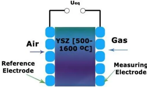
FIGURE 2.16-POTENTIOMETRIC NERNST SENSOR. ... 45
FIGURE 2.17-STRUCTURE OF FET-TYPE SOLID ELECTROLYTE OXYGEN GAS SENSOR. ... 46
FIGURE 2.18-SCHEMATIC DIAGRAM OF A MOSFET GAS SENSOR. ... 47
FIGURE 2.19-ULTRASOUND TRANSMITTER AND RECEIVER UNITS EMBEDDED IN THE CHAMBER... 48
FIGURE 2.20-FUNCTIONAL BLOCK DIAGRAM OF THE MICROMACHINED GAS CHROMATOGRAPHY (GC) SYSTEM. ... 50
FIGURE 3.1-TWO KINDS OF ATOMIC TRANSITIONS EXCITATION AND DE-EXCITATION... 67
FIGURE 3.2-DE-EXCITATION TRANSITIONS OF HYDROGEN ATOM ... 68
FIGURE 3.3-SCHEMATIC DIAGRAM OF THE SPATIAL REGIONS PRESENT IN D.C. GLOW DISCHARGES ... 70
FIGURE 3.4-SCHEMATIC REPRESENTATION OF AN ATMOSPHERIC PRESSURE GLOW DISCHARGE (APGD) ... 73
FIGURE 3.5-SCHEMATIC REPRESENTATION OF AN ANALYTICAL ICP TORCH. ... 74
FIGURE 3.6-THE ELECTROMAGNETIC SPECTRUM ... 77
FIGURE 4.1-EXPERIMENTAL SYSTEM. ... 96
10
FIGURE 4.3.O2(80%)+AR(20%) ... 101
FIGURE 4.4.AR(20%)+HE(40%)+CO2(40%) ... 101
FIGURE 4.5.AR(33%)+HE(33%)+CO2(33%) ... 101
FIGURE 4.6.AR(40%)+HE(40%)+CO2(20%) ... 102
FIGURE 4.7AR(10%)+CO2(20%)+O2(10%)+HE(60%) ... 102
FIGURE 4.8-AR(20%)+CO2(10%)+O2(10%)+HE(60%) ... 103
FIGURE 4.9-AR(20%)+CO2(20%)+O2(30%)+HE(30%) ... 103
FIGURE 4.10-AR(25%)+CO2(25%)+O2(25%)+HE(25%) ... 103
FIGURE 4.11-AR(40%)+CO2(10%)+O2(10%)+HE(40%) ... 103
FIGURE 4.12.THE DISTRIBUTION OF THE TEN COLOR MEASUREMENTS AT THE X-CHANNEL ... 105
FIGURE 4.13.THE DISTRIBUTION OF THE TEN COLOR MEASUREMENTS AT THE Y-CHANNEL ... 106
11
List of Tables
TABLE 2.1-THE TRADE-OFF BETWEEN THE DISCUSSED TYPES OF SENSORS CONCERNING THE DIFFERENT PARAMETERS ... 55 TABLE 3.1-EMISSION LINES AND THEIR CORRESPONDIG PHOTON WAVELENGTH. ... 68 TABLE 4.1-MEAN M AND VARIANCE V OF THE DISTRIBUTION OF THE COLOR MEASUREMENT ERROR. ... 108
12
Abstract
Gases represent one of the most important key measurands in many industrial and domestic activities. The need to detect single gas or a group of gases at the same time varies from one application to another. One of the most important applications of gas sensing is in the concentration measurement of exhaust emissions in internal combustion engines. The variety of gases emitted by these engines and the necessity for a precise measurement of their concentrations are the major incentives for researchers to develop gas sensors that are not only limited to a certain type of gases but to a variety of gases. The most interest gases include CO, NO, NO2, NH4, SO2, CO2, CH4 and other hydrocarbons. These gases can be harmful to human health if present beyond a certain concentration.
The analysis of exhaust emissions of internal combustion engines has traditionally been achieved in laboratories using bulk gas analyzers and costly equipments. In order to create a system which can do the work of these analyzers, a sensor that can measure the concentration of multiple gases at the same time is needed. Instead of using a sensor for each gas which is costly and introduce another complexity to the analysis procedure due to the different technologies that are used in the detection of different types of gases. This directly translates into loss of financial and human resources that could otherwise be productively used. In an effort to remedy this situation, this dissertation proposes an alternate approach that uses one sensor to analyze multiple gases simultaneously. This has a significant potential in reducing the aforementioned complexity, size and data collection tasks, and at the same time can lower the cost of the overall system.
This dissertation presents the design, methodology, and development of a new method for gas concentration measurement using digital image processing through modeling the color mixing of light emissions in gas discharge tube. The application of the inverse model allows us to get the percentages of each gas in a mixture of up to four gases knowing already the color of emission of the whole mixture and the color of emission of each gas alone. It also discusses the miniaturization potential of some of the methods that are promising in the ability of their
13 miniaturization but suffer from different problems. A comparison is also done among the miniaturized sensors in terms of different parameters like sensitivity, selectivity, cost and other terms. In achieving the research objectives, major technical challenges such as color mixing modeling, imaging sensor calibration, and measurements’ error handling have been successfully identified and addressed.
14
New Gas Sensor for Exhaust Emissions of Internal
Combustion Engines
15
1. Introduction
This research objective was to find a new gas sensor used especially in measurement of the concentrations of exhaust emissions of internal combustion engines. The variety of gases emitted by these engines and the necessity for a precise measurement of their concentrations are the major incentives for researchers to develop gas sensors that are not only limited to a certain type of gases but to a variety of gases. The most interest gases include CO, NO, NO2, NH4, SO2, CO2, CH4 and other hydrocarbons. These gases can be harmful to human health if present beyond a certain concentration [1].
Gas sensors have gained a lot of attention in the last decades due to their wide role ranging from industrial applications to atmospheric monitoring. Gas sensing methods are numerous due to the variety of physical parameters that can be measured and can reflect the gas concentration. However, each technology has its strengths and weaknesses and there is no one perfect solution for all applications.
The principle function of a gas sensor is to obtain quantitative or qualitative information about specific gases in a selected ambient; quantitative information like concentrations and partial pressures of specific components or classes of chemical compounds with similar properties such as their flammability in air and qualitative information like the presence or absence of certain odors, detection of organic volatiles exceeding a certain threshold-limited value (TLV), or the lower explosive limits (LEL) of combustible gases.
Depending on the application, the gas sensor has to be carefully designed taking into consideration many factors that affect its performance. The improvement of the sensor sensitivity, selectivity, response time, cost, power consumption and size are the basic goals for research in the field of gas sensing.
In order for a gas sensor to be used effectively in real life applications, the initial and operation costs must be taken into consideration. The miniaturization of the gas sensor can decrease both the cost and power consumption of the sensor, this opened the door toward using gas sensors in new applications and on-site measurements that were only possible in laboratories. Such sensors
16 are intensively searched and many miniaturized sensors have been made [2]. Most of the sensing technologies can lead to a miniaturized sensor with each method has its own pros and cons, however no single technology is the best candidate for miniaturization and it depends on the factors that are mostly important for the application.
1.1 Importance of the Research Activity
Gas sensing is a critical component of constructing and operating of a wide range of applications. A good sensor that can provide fast and accurate measurements of different kind of gases is a key to significant saving in time and costs, and at the same time results in providing important information for decision making and control systems. The ability of measuring concentrations of several gases at the same time with minimum amount of time spent on measurement process, that in many applications are not directly related to the scope of the project, is an important factor in realizing many real-life projects like pollution monitoring or real time industrial control systems. This ability to use one sensor for measuring several gases concentrations at the same time reduces the cost and complexity of the whole operation. This is a major incentive for using such sensor in applications like measuring emissions’ concentrations in internal combustion engines in order to identify and measure gases produced during engine examination and testing or during the course of the real operation. This can identify potential engine related issues and problems that may cause unexpected failure or fuel consumption inefficiency, and plan ahead of time to avoid during actual operation.
For a relatively small number of distinct gases to be measured in a certain application the operation, interpreting, verifying, and validating of the results of measurements can be done manually using a sensor for each gas and numerical tools. However, as the size of the measured gases increases and with the limitation caused by size, cost, power consumption and the need for automating the whole process of measurement, all of these make the presence of one low cost sensor that can measure several gases simultaneously turns into a crucial need.
Amongst several approaches of gas sensing methods, Optical Emission Spectroscopy (OES) has gained significant credibility since it can detect and analyze almost any kind of gas and it results in an accurate measurement of concentration. OES provide both quantitative (gas concentration) and qualitative (gas identification) results. One of the effective methods of interpreting the
17 results of an OES system is to use digital spectroscopes. However the cost of using such system is relatively high and their sizes limit the overall miniaturization potential of the sensor. The introducing of the digital image processing for the spectrum of the gases can be an effective mean to achieve this objective and reduce the need of complex bulk spectroscopes to analyze the optical emission of gases under measurement.
The application of image processing in plasma imaging has been investigated by several researchers [3]. In contrast, there have been very few studies conducted in gas sensing primarily due to the fact that the successful implementation of a digital imaging system requires addressing several critical challenges and problems in order to produce an acceptable degree of reliability and credibility in the measured results.
Gas sensing technology can offer high potential for significant improvement in many scientific and engineering domains such as industrial, medicine and manufacturing. For example, using gas sensors in space missions can allow the monitoring of oxygen levels and detect toxic gases in space shuttles. It can also be applied to detect pollution levels within the atmosphere and in living areas like big cities where exceeding a certain limit of some gases can be considered as a life threatening issue. Gas sensing can also help car manufacturers in providing required percentage of pollutants and design different components to enhance fuel efficiency.
1.2 Applications of Gas Sensors
Gas sensors are widely used in many fields ranging from industrial to domestic applications. The application where the sensor is used is the key factor behind choosing the type of the gas sensor as not all types fit all applications. Some of the applications are:
Air pollutant measurement.
Human breath analysis and disease detection. Life support in manned space applications. Car ventilation control.
Gasoline vapor detection. Alcohol breath tests.
Safety (Fire detection, Leak detection). Toxic/flammable/explosive gas detectors.
18 Indoor air quality.
Air purifiers. Ventilation control.
Environmental control (Weather stations & Pollution monitoring). Food quality and Process control.
Industrial production like in fermentation control. Medical Breath analysis.
Prevent of industrial gases emissions especially near large towns, plants.
1.3 Prior State of Knowledge
Gas sensing related research has been conducted in a growing number of scientific and engineering disciplines. Integration of a gas sensor in many products helps manufacturing companies (e.g. automotive, airlines, etc.) to monitor gas emissions concentrations and pollution. The gas sensing technologies are wide and diverse due to the several physical and chemical effects that can be measured and reflect the gas characteristics [4]. Commercial and conventional methods in gas sensing like infrared spectroscopy, gas chromatography or mass spectrometry (GC/MS) are considered to be good methods, they have good detection limits and fast response times but they are relatively bulky and expensive [5]. Thus new methods for gas sensing were needed to take place the conventional ones, however most of the new emerged sensing techniques still depend on the same principles of the old ones.
The conducting polymer gas sensors have been in continuous research for liquid petroleum gas sensing [6] and humidity sensors [7] and showed a good selectivity and sensitivity. Piezoelectric gas sensors measures variations in the propagation of acoustic waves, or the changes of physical properties of interfacial thin films caused after exposition to an analyte, they are divided into two parts: bulk acoustic wave (BAW) or quartz crystal microbalance (QCM) and surface acoustic wave (SAW) detectors [8]. The ultrasound based sensor [17] can detect the changes in the gas concentrations by measuring the attenuation of the ultrasound waves caused by the gas under measurement. Carbon nanotubes CNT-based gas sensors can be classified into chemical and physical types. Chemical CNTs gas sensors depend on the changes of their conductivity and permittivity due to the gas adsorption. Several sensors of this type have been reported [9]. They have extremely small size, high sensitivity, and low cost of manufacturing and a good electrical
19 response even at room temperature [10]. Physical CNTs gas sensors utilize the gas ionization technique invoked by applying high voltage [11]. CNTs suffer from a problem that they could be oxidized and degraded easily in the presence of oxygen. Semiconductor gas sensors are typically based on metal oxides (like SnO2, TiO2, etc.) they have many advantages like low cost, high sensitivity, simplicity and its easy integration with other elements [2] but with poor reproducibility and long-time instability due to aging, nonlinearity, and lack of selectivity of certain gas measurement when different reactive gases exist in the same atmosphere that cause interference.
Optical methods in gases detection are numerous like ellipsometry, spectroscopy, interferometry and surface plasmon resonance (SPR) [12]. Optical emission spectroscopy (OES) techniques are often used in chemical laboratories as analyzers, also they have been used in instruments for air pollutant measurements [13] also a small sized OES based sensor for exhaust emission has been reported [14]. Optical spectroscopy gas detection techniques are rapid and often provide highly selective means of measuring gas concentration with good sensitivity they also have a good precision, their disadvantages are in being expensive and the measured gas must have a significant and distinct absorption, emission or scattering in a convenient region of the optical spectrum in order to be detectable [15]. Optical fiber based gas sensors have small size and light weight, remotely operated, they have an electromagnetic immunity which enable them to work in high noise environment, and they are also passive devices and require no electric power in the sensing zone which makes them reliable in environments with flammable gases [16].
Each of the above mentioned sensors, however, was focused on developing a domain specific gas sensor that was intended for a very specific purpose, thereby limiting its widespread applicability. For example, some methods were developed for the detection of a single gas and others required specific conditions to work. In addition, prior research in gas sensing:
Does not consider using same sensor for measuring multiple gases simultaneously in a real time scenario.
Does not afford unrestricted mobility to the gas sensor to be used on-site in applications that require dynamic way of measurements like in moving vehicles.
20 Does not consider the cost and operation costs of using multiple sensors to measure
multiple gases in the same application.
Does not consider problems associated with using gas sensors in unprepared environments.
1.4 Research Objectives
In order to address the limitations in the existing state of knowledge, the overall objective of this research was to develop a relatively low cost gas sensor, with the ability to measure multiple gases concentrations at the same time, which can be used for measuring the concentration of gases emitted by internal combustion engine. Also this research investigates the miniaturization potential of several gas sensing technologies for recommending the best candidate among the studied sensors for miniaturization.
The specific objectives of this research were identified as follows:
Study both existed and novel methods used in gas sensing technologies and sensor design methods determining the required parameters (i.e. sensitivity, selectivity, power consumption, and size) that can evaluate the sensor efficiency.
Study the methods used in various sensors to obtain and retrieve the sensor’s data to determine the complexity, response time and cost in processing data gathered by the sensor. As in the optical emission spectroscopy where the using of a spectrometer implies a high cost and increase in the size of the overall system.
Review and discuss the miniaturization potential of the most existed and novel gas sensors and search for best candidate among them based on several criteria.
Investigate feasible methods to apply to obtain a sensor that can measure multiple gases at the same time, with a relatively low cost, in order to apply on the internal combustion engines’ emissions measurement. For our goal we found that the optical methods and especially the ones that depend on gas emissions under electric fields is a good candidate due to its high selectivity and sensitivity.
Develop an expressive yet simple method to analyze the gas emissions to replace the spectroscopes and spectrographs. The developed method depends on digital image processing to register and process the color emitted by gas under experiment.
21 Identify and effectively address issues such as errors in measurements that significantly affect the precision and credibility of the sensor. Such issues arise from the imaging sensor and the impurities in the gas mixtures.
This dissertation presents the developed methodology and the design of an optical based gas sensor with the detailed study the state of the art gas sensing technology. It explains the operation mechanism, data processing algorithms, and sensor calibration together with their practical implementation inside an experiment. The designed sensor provides a convenient method to automatically measure a mixture of up to four gases simultaneously using a low cost technique. The results of the research have been tested and validated by the experiment and the measurement error has been determined by making several controlled measurements using different gas mixtures.
1.5 Research Methodology
In order to effectively achieve the objectives of this research, the identified problems and challenges were clustered into several groups for investigation. The following is an abridged list of the major steps followed in this research to fulfill the requirements of a functional, reliable, and practical gas sensor capable of measuring the concentration of several gases simultaneously that can be conveniently used in internal combustion engines gas emissions and in many other applications:
Studied the details of involved parameters in gas sensing without dependence on any type of sensors or applications that might possibly limit the criteria of parameter selection. Reviewed the existed and novel gas sensing technologies and discussed their
miniaturization potential making a comparison between the most important categories for the aim of miniaturization.
Created a model for light color mixing in gas discharge emissions to understand the phenomena and applied the reverse model to determine the gas concentration in the discharge from the color emitted.
Build an experiment to validate the proposed model of light mixing in gas discharge tube and for the testing and validation of the proposed gas sensing method that rely on the image processing of the color emitted by the gas under the discharge tube.
22
1.6 Dissertation Outline
During the course of this research, the author produced several scientific manuscripts in the form of journal papers as each identified challenge or research problem was successfully addressed. Each chapter serves as a stand-alone document that describes the details of individual scientific questions successfully addressed, major challenges involved, and algorithms and methods studied, adopted, developed, and implemented in achieving a particular research objective. Each Chapter concludes with an extensive list of references (books, papers, and internet URLs) that direct the reader to further resources related to the main topic of the chapter. In Chapter 2, the review of recent trends in gas sensing technology and their miniaturization potential is introduced and described. The pros and cons of each studied technology and the comparison between these methods for the aim of sensor miniaturization are presented. Chapter 3 describes the theory of plasma emission and gas discharge tube, optical emission spectroscopy. In Chapter 4, we introduced the color mixing model, and the theoretical model of the proposed sensor in this research and its integration into a real experiment, the experiments were done to test and validate the results from several validation experiments that has been conducted to evaluate the functionality and reliability of the developed sensor.
23
1.7 References
[1] Sharma, S. and Madou, M. (2011), “A new approach to gas sensing with nanotechnology”, Phil. Trans. R. Soc. A, Vol. 370, pp. 2448-2473.
[2] Pearce, T.C., Schiffman, S.S., Nagle, H.T. and Gardner, J.W. (2003), Handbook of Machine Olfaction, Wiley-VCH, Weinheim.
[3] Doroodmand , M. M. and Darabpour, M. (2014), “Image processing of non-thermal glow discharge plasma during gas ionization process as a novel hydrogen detection system at parts per billion levels”, International Journal of Hydrogen Energy, Vol. 39, Iss. 7, pp. 3564–3571
[4] Sari Lakkis, Rafic Younes, Yasser Alayli, Mohamad Sawan, (2014) "Review of recent trends in gas sensing technologies and their miniaturization potential", Sensor Review, Vol. 34 Iss: 1, pp.24 – 35.
[5] Akbar, S. (2006), “High-temperature ceramic gas sensors: a review”, International Journal of Applied Ceramic Technology, Vol. 3 No. 4, pp. 302-311.
[6] Aashis, S.R., Machappa, T., Prasad, A. and Koppalkar, R.A. (2011a), “Sensitivity and selectivity studies on polyaniline/ molybdenum trioxide composites to liquid petroleum gas”, Sensors & Transducers Journal, Vol. 125 No. 2, pp. 220-228.
[7] Parveen, A., Koppalkar, A.R. and Roy, A.S. (2012), “Surfacemodified CaTiO3 loaded in polyaniline by sodium dodecyl benzene sulphonic acid for humidity sensor”, IEEE Sensors Journal, Vol. 12 No. 9.
[8] Gabl, R., Feucht, H.-D., Zeininger, H., Eckstein, G., Schreiter, M., Primig, R., Pitzer, D. and Wersing, W. (2011), “Gas sensors based on gravimetric detection: a review”, Sensors and Actuators B, Vol. 160, pp. 804-821.
[9] Kong, J., Franklin, N.R., Zhou, C., Chapline, M.G., Peng, S., Cho, K. and Dai, H. (2000), “Nanotube molecular wires as chemical sensors”, Science, Vol. 287, pp. 622-625.
[10] Kim, S. (2006), “CNT sensors for detecting gases with low adsorption energy”, Ionization Sensors, Vol. 6, pp. 503-513.
24 [11] Gavrilov, S.A., Il’ichev, E ´ .A., Poltoratskii, E ´ .A., Rychkov, G.S., Dvorkin, V.V., Dzbanovsky, N.N. and Suetin, N.V. (2004), “Carbon nanotube field emitters for planar emission vacuum micro- and nanoelectronics”, Tech. Phys. Lett., Vol. 30, pp. 609-611.
[12] S. Capone, A. Forleo, L. Francioso, R. Rella, P. Siciliano, J. Spadavecchia, D. S. Presicce, A. M. Taurino, Solid State Gas Sensors: State Of The Art and Future Activities. Journal of Optoelectronics and Advanced Materials Vol. 5, No. 5, p. 1335 – 1348, (2003).
[13] Lee, D. D. and Lee D. S., (2001a), “Environmental Gas Sensors”, IEEE Sensors Journal, Vol. 1, No. 3, (2003).
[14] Mello, M., De Risi, A., Passaseo, A., Lomascolo, M. and De Vittorio, M., “Carbon-monoxide (CO) Real Time Monitoring in Combustion Engines by an Optical Detection System”. IEEE Research in Microelectronics and Electronics, PP. 433 – 436, (2006).
[15] Dakin, J. P. and Chambers, P., Review of Methods of Optical Gas Detection by Direct Optical Spectroscopy, with Emphasis on Correlation Spectroscopy, Optical Chemical Sensors, pp. 457–477, (2006).
[16] Elosu, C., Matias, I.R., Bariainemail, C. and Arregui, F.J., “Development of an In-Fiber Nanocavity Towards Detection of Volatile Organic Gases”, IEEE Sensors, Vol. 6, pp. 578-592, (2006).
[17] Toda, H. and Kobayakawa, T. (2008), “High-speed gasconcentration measurement using ultrasound”, Sensors and Actuators A, Vol. 144, pp. 1-6.
25
2. Review of Recent Trends in Gas Sensing Technologies and their
Miniaturization Potential
2.1 Introduction
Gases represent one of the most important key measurands in many industrial and domestic activities. The most interest gases include CO, NO, NO2, NH4, SO2, CO2, CH4 and other hydrocarbons. These gases can be harmful to human health if present beyond a certain concentration [1]. The applications of the sensors vary from the need to detect single gas or a group of gases at the same time; this is expressed by the term selectivity which is the ability of the sensor to detect what is interest over what is not interest [2].
The diversity in gas sensing methods are due to the several physical and chemical effects that can be measured and reflect the gas characteristics. However, each technology has its strengths and weaknesses and there is no one perfect solution for all applications.
A great deal of research is directed toward the miniaturization of gas sensors, this can lead to reduced weight, lower power consumption, and lower cost gas sensors. Recently, new sensing technologies appeared where they offer good promises for the design of robust miniature sensors. In this review we will discuss the conventional and the novel techniques used in gas sensors. We will also discuss the research done in the miniaturization of these sensors and compare between them to find the best candidate for miniaturization.
2.2 State of the Art
Many reviews of gas sensors had been published but most of them are specific to a certain type of sensors, due to the diversity of technologies used, or specific to a certain application. Metal Oxide Semi Conductor (MOS) gas sensors were reviewed by many [1,7,11,12,92,94]. In [1] Sharma and Madou reviewed the evolution in both the gas-sensitive materials used and the heater structures of MOS, they discussed the miniaturization from macro to nanosize of both the sensor and its heating element. In [7] the 1-D nanostructured Metal-Oxides based sensors were
26 reviewed evaluating their performance.In [92] MOS gas sensors specific to Environmental Monitoring were reviewed. Bai and Shi in [18] reviewed gas sensors based on conducting polymers, they discussed the sensing mechanism, configurations and the factors that affect the performance, listing some of the disadvantages. Gas sensors based on gravimetric detection was reviewed by L. Duraffourg et al in [10], Xu et al. reviewed the Zeolite-based materials for gas sensors in [66] highlighting the potential of these materials in gas sensing especially in terms of sensor selectivity. Kauffman and Star in [37] reviewed the carbon nanotube gas and vapor sensors considering it a promising new technology in terms of sensitivity and selectivity. Ceramic gas sensors that operate at high temperatures were reviewed by Akbar et al in [3]. Gas sensors based on electrospun nanofibers was reviewed by Ding et al. in [93] featuring them in terms of sensitivity and response time over sensors based on flat films. A review of gas sensors employed in electronic nose applications was done by Arshak et al. in [5].
In this chapter, we will review most of the methods used in gas sensing and discuss their miniaturization potential delimiting our research to a certain type of technology or application.
2.3 Conducting Polymer Gas Sensors
The first type of gas sensors to be discussed is the conducting polymer gas sensors.They have been in continuous research for Liquid Petroleum Gas sensing [16, 17] and humidity sensors [19, 22] and showed a good selectivity and sensitivity.
2.3.1 Conducting Polymer Chemiresistor Gas Sensors
Chemiresistor polymer gas sensors [18] consist of a layer of conducting polymer connected to one or several pairs of electrodes, as illustrated in Figure 2.1.
27 Figure 2.1 - The General Structure of a Chemresistor.
The electrical resistance change of the sensing material, due to gas interaction, is measured as the output. A constant current or potential can be applied on the sensor, and the measuring output signal is their changes, respectively. Also alternating current (AC) can be used [20, 26], in this case the capacitance C and inductor L should be included since they are both affected by the gas interaction with the sensing film. Another value can be taken into account; the value of dissipation factor (resistance/absolute value of reactance) that changes with frequency, where the peak position in the dissipation versus frequency curve is shifted when exposed to different gases. This shift is unique for each gas [23] and can be used to detect the type of the gas.
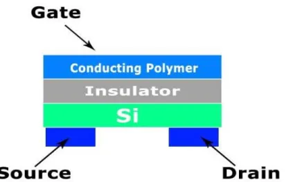
2.3.2 Conducting Polymer Transistor and Diode Gas Sensors
Transistors and diodes have more parameters for measurements than the chemiresistor polymer and have better detection limit and sensitivity because of the signal amplification of transistor devices and diode conducting polymers are simpler than transistors. Based on semiconductor properties, the polymer transistor gas sensors works by applying a source-drain voltage and measuring a source-drain current modulated by a gate potential as an output. The output current is changed when the polymer sensing film interacts with an analyte (Figure 2.2). Conducting polymer transistors are classified according whether the current passes through the conducting polymer or not [18].
28 Figure 2.2 - Thin film transistor (TFT) with aconducting polymeractive layer.
There are other types of polymer based gas sensors like the optical polymer gas sensors [24, 25] where gas can be analyzed when it is in contact with the conducting polymer film by measuring transmittance or absorbance changes. Conducting Polymers can also be used in piezoelectric crystal sensors. Recently research is focusing on enhancing certain parameters like sensitivity [21] by incorporating different materials.
2.4 Piezoelectric Crystal Gas Sensors
Piezoelectricity was observed by Pierre and Jacques Curie in 1880, when a quartz crystal is compressed, an electric potential is produced. On contrary, if an alternating electric potential is applied on a piezoelectric material, an acoustic waves in solids is generated, see Figure 2.3.
29 Piezoelectric crystal gas sensors are divided into two parts; bulk acoustic wave (BAW) or quartz crystal microbalance (QCM), and surface acoustic wave (SAW) detectors (Figure 2.4). For a detailed review of SAW and BAW gas sensors refer to [10].
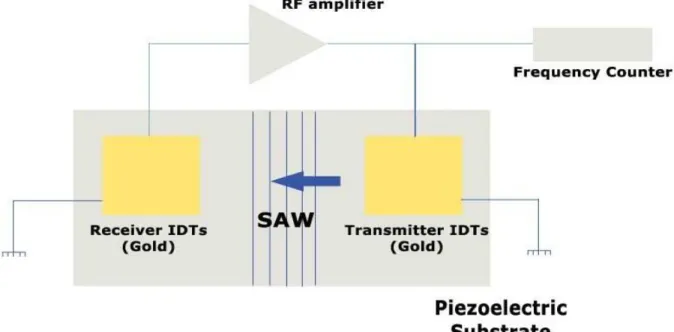
Figure 2.4 - Schematic diagram of a SAW sensor.
In both types, the sensor is made of a piezoelectric substrate coated with a suitable sorbent coating where the gases are detected by their effect on the propagation of the acoustic wave causing changes in the resonant frequency and the wave velocity as the adsorption of gas onto the coating surface cause a shift in the oscillation frequency corresponding to the mass of the adsorbed compound. [6].
Sensing in piezoelectric gas sensors is done by measuring variations in the propagation of acoustic waves, or the changes of physical properties of interfacial thin films caused after exposition to an analyte. Sensors based on ultrasound technique [81] can detect the changes in the gas concentrations by measuring the attenuation of the ultrasound waves caused by the gas under measurement.
30 Figure 2.5 - Schematic diagram of AT-cut quartz crystal. (a) The structure of AT-cut quartz crystal, A: Quartz crystal, B: Electrode, C: Lead wire. (b) The principle of piezoelectric quartz crystal and oscillation model. (c) Electrical equivalent circuit. (d) Mechanical model.
The QCM (Figure 2.5) detection principle is based on the fact that the change in resonance frequency of a thin quartz crystal covered with a gas sensitive layer is proportional to the additional mass of the adsorbed gas atoms. The detection limits of the QCMs are in the parts-per-million (ppm) range [10].
31 Figure 2.6 - Schematic diagram of a portable piezoelectric-resonance gas analyzer: (1) permeable filter with a selective adsorbent; (2) switching valve; (3) CPRMS; (4) micropump; (5, 6) high-frequency oscillators; (7) reference resonator (or SWA sensor); (8) frequency transformer; (9) control and data processing unit; (10) indicator; (11) power supply unit.
In SAW, the sensor consists of two separated electrode pairs on a substrate playing a role of a transmitter and receiver of acoustic waves. The separation region is coated with gas sensitive substances that allow adsorption of gas atoms that change the phase and/or amplitude of the SAW. SAW devices operate at much higher frequencies than BAW systems (about 10 times). The lower detection limit for these SAW sensors lies in the range of a few ppb [10].
The sensitivity in SAW is directly proportional to the square root of resonant frequency, and inversely proportional to the surface area which is very small. SAW devices have a relatively low fabrication cost and they can be miniaturized with precise and reproducible characteristics using photo-lithographic techniques [9]. However AT-cut quartz is more stable than SAW device.
32 Chemical piezoelectric-resonance mass sensors (CPRMSs) for gas sensing application had also been intensively developed [29-31]. These sensors (Figure 2.6) usually have a fast response and long lifetime.
The advantages of piezoelectric gas sensors are in being sensitive, relatively cheap and have a fast response time. Their disadvantage is their limited selectivity which depends on the availability of coating layers. Other special issues related to SAW detectors are noise and higher costs for materials due to the higher operating frequency.
2.5 Carbon Nanotubes (CNTs) Based Gas Sensors.
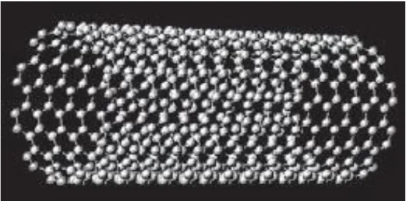
CNTs are hexagonal networks of carbon atoms; they are about 1 nm in diameter and from 1 to 100 microns in length. There are two types of nanotubes: single-walled nanotubes (SWNTs) and multi-walled nanotubes (MWNTs); SWNTs have only one layer of graphene cylinders (Figure 2.7); while MWNTs have about 50 layers.
Figure 2.7 - A single-walled nanotube structure.
Carbon nanotube (CNT)-based gas sensors can be classified into chemical and physical types. Chemical CNTs gas sensors depend on the changes of their conductivity and permittivity due to the gas adsorption. Several sensors of this type have been reported [33 - 36].
They have extremely small size, high sensitivity, and low cost of manufacturing [37] and a good electrical response even at room temperature [38].
33 Physical gas sensors utilize the gas ionization technique invoked by applying high voltage [39, 40]. They have stable structure under high electric fields and considered one of the best field emitters among conventional field emitting metals.
Kong et al [33] showed that the electrical resistance of semiconducting SWNTs changes when exposed to gaseous molecules, having a response time of at least an order of magnitude faster than those based on solid state sensors. They have small size and operate at room temperature with a high sensitivity.
In another study by Modi et al. [41] proposed sensors that have good selectivity and sensitivity, and were unaffected by various environmental conditions (moisture, temperature, and gas-flow), featuring the electrical breakdown of gases mixtures at the tips of CNTs, the cathode of the sensor was made of aluminum and the anode was vertically aligned MWNT film. The proposed method was for solving what they called certain limitations of sensors based on electrical conductance changes (poor diffusion kinetics, inability to identify gases with low adsorption energies and high sensitivity to changes in moisture, temperature and gas-flow velocity).
Surface acoustic waves (SAWs) sensors coated by CNTs with high sensitivity were also reported [42]. The sensor was used for the detection of volatile organic compounds.
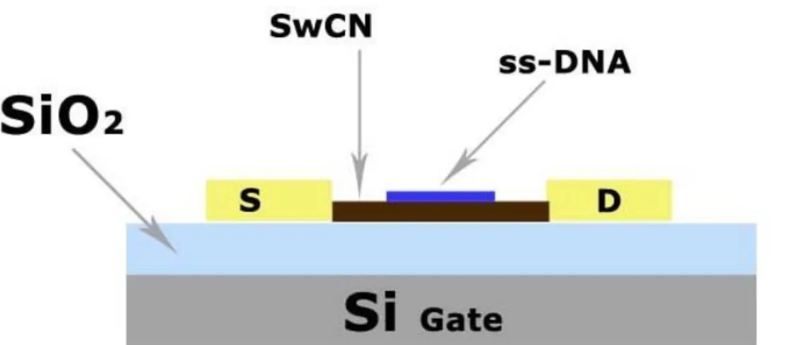
Sensors based on single-stranded DNA (ss-DNA) and SWNT field effect transistors (FETs) have been proposed [43], the sensor (Figure 2.8) can detect variety of gases with rapid response time and have a fast recovery time.
34
2.6 Optical Gas Sensors
Optical methods in gas sensing are diverse; some are widely used like spectroscopy and surface plasmon resonance (SPR) while others are less known like ellipsometry [53].
2.6.1 Optical Spectroscopy
Optical spectroscopy gives quantitative and qualitative information of gases [12]. The emitted or absorbed electromagnetic radiation spectrum tells us about the concentration or the quantitative information, while the qualitative information is related to the wavelengths of the spectrum. Mainly three different techniques are used: atomic absorption spectrometry (AAS), optical emission spectrometry (OES) and atomic fluorescence spectrometry (AFS). These techniques are often used in chemical laboratories as analyzers, also they have been used in instruments for air pollutant measurements [13].
The first optical gas sensors were based on the absorption spectrum difference measurement like the infrared IR gas detectors which have been in use for long time ago, they have long life time with greater stability over time. Their disadvantages are that they can only detect gases that are strongly absorbent in the infrared spectrum like hydrocarbons, they require a relatively large volume of gas for response testing and their ambient temperature is limited to 70oC [7].
Inductively Coupled Plasma-Atomic Emission Spectroscopy (ICP-AES) (Figure 2.9) is one of several techniques available in analytical atomic spectroscopy. ICP-AES utilizes plasma as the atomization and excitation source. Plasma is an electrically neutral, highly ionized gas that consists of ions, electrons, and atoms. The ICP is a radiofrequency-(RF, 27.12 MHz, 40 MHz) induced plasma that uses an induction coil to produce a magnetic field (H). The ICP operates between 1 and 5 kilowatts. The induction coil is wrapped two or three times around the ICP torch and has water flowing through it for cooling purposes. All ICPs have a capacitor bank that is continuously tuned to match the plasma’s inductance. In order for the RF to travel along the surface of the hollow coil with minimum resistance, the coil is either gold or silver plated since neither gold nor silver forms metal oxides upon contact with air. Although the RF power supply maintains the plasma, a tesla coil is used to ignite the plasma through the generation electrons and ions that couple with the magnetic field.
35 Figure 2.9 - SCHEMATIC OF AN ICP TORCH.
Small sized OES based sensor for exhaust emission has been reported [44] and another handheld micro-system to analyze chemicals both in vapor and liquid phases using discharge spectroscopy was presented in [46]. Furthermore, the design and fabrication of micro-machined silicon plasma igniters, that can operate at atmospheric pressure and under a relatively low voltage (400V), for using in gas sensing was reported in [45].
36 Optical spectroscopy gas detection techniques are rapid and often provide highly selective means of measuring gas concentration with good sensitivity they also have a good precision, their disadvantages are in being expensive and the measured gas must have a significant and distinct absorption, emission or scattering in a convenient region of the optical spectrum in order to be detectable [14].
2.6.2 Ellipsometric Gas Sensor
An optical gas sensor, with sensitivity in the ppm range for vapors of alcohols, based on polarizer compensator sample analyzer (PCSA) ellipsometric readout system working in the off-null mode (Figure 2.10) was reported in [53]. The principle of this sensor is based on the detection of the intensity change of polarized light that is reflected by a sensing layer exposed to gas in oblique incidence; this intensity change holds the information about gas concentrations.
Figure 2.10 - Optical setup of the ellipsometric gas sensor system.
The sensing layers suitable for this system are thin layers (0.01–10 m) thickness deposited on silicon or metal substrates where their refractive index and/or thickness can change reversibly due to the gas exposure.
37 2.6.3 Non Dispersive Infrared (NDIR) Gas Sensor
Gas molecules selectively absorb radiation according to their quantized vibrating energy; the absorption degree is proportional to the concentration of the gas [47]. The principle of this sensor is bases on the absorption of infrared (IR) light by the gas to be measured [48], where a source of light with a radiated energy I is emitted and directed through a path of length l containing the gas sample, with concentration and absorptivity C and α, then the radiated energy I0 after absorption is detected by the IR detector according to Beer-Lamberts law (eq.1).
I(t)=I0(t)exp(-α()LC)
(eq.1)
Where I(t)is the output light intensity, I0(t) is the input light intensity, α is the absorption coefficient, L is the optical path length, C is the concentration of gas sample. Using a monochromatic beam with a large absorptivity enables the detection of the concentration of the target gas without interfering with the other gases [47].
A similar technology is used in photoacoustic gas sensor [54, 48] where the ratio I/I0is detected using a pressure sensor as a varying over time pressure signal.
NDIR sensor is selective and several commercial sensors detection exists with detection limit down to 30 ppm for CO2 [49] and 200 ppm for hydrocarbons [50] with size in order of centimeters.
2.6.4 Photoacoustic Gas Sensor
The principle of this sensor is similar to the (NDIR) technique where the ratio I/I0is detected using a pressure sensor as a varying over time pressure signal.
38 Figure 2.11 - Principle of a photoacoustic gas sensor with IR-emitter, surveillance.
As illustrated in (Figure 2.11) the absorption of the IR radiation by the target gas, enclosed in the absorption chamber of the PA cell, heats up the gas which increase the pressure in the absorption chamber. The incident light is modulated at a given frequency which gives a periodic pressure variation in the absorption chamber
The target gas which is presented in the surveillance path, will cause absorption of the IR radiation by the tested gas outside the PA cell and therefore reduce the radiation intensity that is entering the absorption chamber. This will cause a less heating of the enclosed gas in the PA cell, and invoke a reduction in the amplitude of the periodic pressure signal. This reduction in pressure amplitude is logarithmic and it is proportional to the concentration of the target gas in the surveillance path.
2.6.5 Active Laser Gas Sensor
Active Laser gas sensors have a major application in the remote measurement of gas concentrations like the in situ measurements of impurity gases of the atmosphere [51]. The principle of these sensors depends on the reflection of the laser beam, emitted by the sensor, from various obstacles like earth surfaces, buildings, roads, etc.), the measurement of the reflected light is done at specified wavelengths corresponding to the absorption ones of gases to be measured and this allows the determination of their concentrations.
39 When employing a high power pulsed solid state laser [52] particle concentrations can be determined at distances up to 1–2 km with an accuracy of about 0.1 ppm which is high enough for the monitoring of SO2, NO and NO2 gases in the atmosphere.
2.6.6 Surface Plasmon Resonance (SPR) Gas Sensors
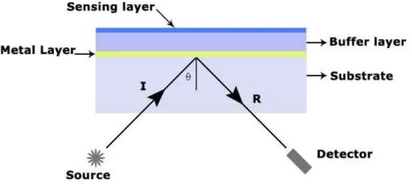
SPR sensors are based on Kretchmann-Raether geometry [55]; they consist of thin metal film deposited on the surface of a glass substrate (Figure 2.12).
Figure 2.12 - SPR-based sensor schematic diagram.
In their functioning principle the source light is a p-polarized incident light excites an electrondensity surface plasmon wave (SPW) along the metal. In SPR based sensor, the angle of incidence of the light beam is varied at fixed wavelength and the intensity of reflected signal is measured, the change in the refractive index of the sensing medium shifts the resonance to a different value [56]. Measuring the light reflected from the sensor interface can be done by several methods. These include analysis of angle modulation, wavelength modulation, intensity modulation and phase modulation. Many gases like toxic gases such as ammonia, toluene, xylene, ethylacetate, 4-methyl-2-pentanone and propionic acid can be detected by measuring the SPR using angle modulation [6].
40 2.6.7 Optical Fiber Gas Sensors
Optical Fiber Gas Sensors appeared lately in the past two decades. For their application in gas sensing, the optical changes in the optic fiber are used as the response mechanism for the detection of gases or odors. The sides or tips of the optic fibers are coated with a fluorescent dye encapsulated in a polymer matrix, when interacted with gases the dye’s optical properties such as intensity, spectrum, lifetime or wavelength shift in fluorescence are changed [5].
Absorption spectrum optical sensors are considered kind of practicality sensors [57-59] since they are more sensitive than other optical sensors, can conduct higher respond speeds, less affected by temperature or humidity and have a simpler structure and higher credibility.
A method based on harmonic detection was developed by [59], according to the Beer-Lambert Law, in this sensor the light intensity is attenuated when it passes through the gas sample due to the absorption effect. In this sensor the wavelength of light source is modulated and the wavelength scan is made through the entire absorption peak periodically according to sine function. The harmonic is produced due to the interaction between light and gas absorption peak and from this harmonic analysis the concentration of gas sample is calculated where the fundamental wave component is obtained from the difference between referenced light intensity and metrical light intensity and the gas concentration is then obtained from detecting the 2nd harmonic of the difference signal. The sensor was able to detect concentration of acetylene greater than 20ppm and has a linear output proportion to gas concentration, if the gas concentration is greater than 40ppm.
Another sensor that is based on thermal lens (TL) spectroscopy was also reported in [60] as an all-fiber TL gas sensor system with a fiber ring laser, which was a new approach for TL techniques, featuring an optical absorption path with a shorter length than other optical spectroscopic techniques. The proposed sensor effectively enhanced sensitivity and increased the limit of detection by twice.
Optical fiber based gas sensors offers some important advantages; they have small size and light weight, remotely operated, they have an electromagnetic immunity which enable them to work in high noise environment, they are also passive devices and require no electric power in the sensing zone which makes them reliable in environments with flammable gases [61].
41
2.7 Semiconductor Gas Sensors
Semiconductor are chemoresistive or Conductometric gas sensors, they are typically based on metal oxides (like SnO2, TiO2, etc.). Metal oxides are deposited as thin films through vacuum deposition onto a silica or aluminum oxide substrate in a similar process to that used for fabricating semiconductors. Semiconductor gas sensors are used for the detection of combustible gases at low concentration levels and in toxic gas detection. They are robust but also very sensitive to humidity and have low selectivity.
2.7.1 Metal-Oxide Semiconductor (MOS) Gas Sensors
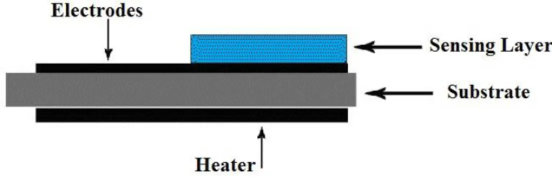
Semiconductor gas sensors are typically based on metal oxides (like SnO2, TiO2, etc.) their interaction with the gas results a reversible and significant change in electrical resistance due to phenomena occurring at the surface like: reduction/oxidation processes, adsorption of the gases and surface chemical reactions between the different adsorbed chemical species. The sensor detects gases from the change in the electrical resistance of a porous sensing body [4].The sensitivity depends on the sensor’s film thickness and the operation temperature, where thinner films being more sensitive [5]. A heating element is used to elevate the sensor’s temperature in order to reduce response and recovery times. The heating element can be a platinum or platinum alloy wire, a resistive metal oxide, or a thin layer of deposited platinum (Figure 2.13).
42 The selectivity of the sensor can be changed to detect different gases or compounds by changing the operating temperature of the sensor or by modifying the sensing films [6].
Semiconductor metal oxide-based gas sensors can be divided into two principal types according to changes in the surface conductance or changes in the bulk conductance during the gas/solid interactions [11]. The working temperature varies depending on the target gas and on the sensor material.
Ralf Moos et al. in their review [62] discussed the novel trends in semiconductor gas sensors differentiating between the n-type, p-type and zeolites. The n-type (zinc oxide, tin dioxide, titanium dioxide or iron (III) oxide) responds to reducing gases where the redox process occurs at surface and p-type (nickel oxide, cobalt oxide) responds to oxidising gases [63, 5] wherethe reduction process affects the entire bulk [64].
2.7.2 Zeolite-Based Semiconductor Gas Sensors
Zeolites have a particular interest in the field of gas sensing, they were mainly used in gas sensing indirectly [65- 67] for example as a filter for the interfering or as gas-sensitive agent encapsulation, however, recent researches were done on using the zeolite itself as the sensitive element in the gas sensor.
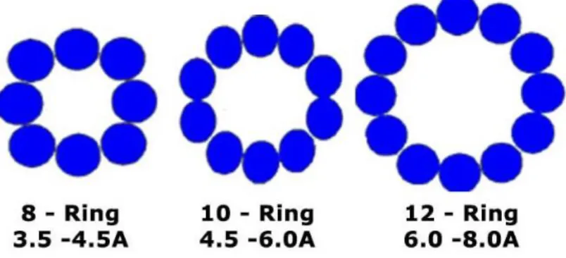
Zeolites are class of aluminosilicates that consist of Si or Al denoted by T that form a framework of tetrahedral building units of TO4 (Figure 2.14).
Figure 2.14 - Structure of different typical Zeolite windows with 8, 10 and 12-ring of TO4 units.
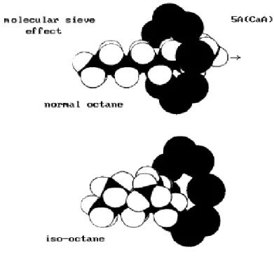
The molecular sieve effect is caused by the different cages with different window sizes that allow some molecules to pass through or not. The ion-exchange with different cations causes the
43 modification of the pore size, the ion conductivity, the adsorption and catalytic selectivity (Figure 2.15).
Figure 2.15 - Molecular Sieve Effect.
Zeolite-based gas sensors were reported in several publications, a robust impedimetric zeolite sensor [68] was used for automotive exhaust gas applications; it didn’t show any significant cross-interference of hydrocarbons, CO2, CO, and O2 when operated at 420 °C. Other sensors were also reported for O2, CO2, CO, NH3 and amine [69], humidity, combustible gases, NO, SO2, Hydrocarbon and organic molecules.
The semiconductor gas sensors have many advantages like low cost, high sensitivity, simplicity and its easy integration with other elements that simplifies the design of a sensor, a detection limit up to 100 ppm of CO could be achieved, which is higher than the highest values, so far achieved with various devices, by two orders of magnitude. Also they have many disadvantages like poor reproducibility and long-time instability due to aging, non-linearity, cross sensitivity effect when measuring a certain gas concentration, where the sensor response is affected by other gases; this is fixed by using more than one sensor or more than one operation modes of the same