HAL Id: lirmm-00348606
https://hal-lirmm.ccsd.cnrs.fr/lirmm-00348606
Submitted on 19 Dec 2008
HAL is a multi-disciplinary open access
archive for the deposit and dissemination of
sci-entific research documents, whether they are
pub-lished or not. The documents may come from
teaching and research institutions in France or
abroad, or from public or private research centers.
L’archive ouverte pluridisciplinaire HAL, est
destinée au dépôt et à la diffusion de documents
scientifiques de niveau recherche, publiés ou non,
émanant des établissements d’enseignement et de
recherche français ou étrangers, des laboratoires
publics ou privés.
A Lossy JPEG2000-based Data Hiding Method for
Scalable 3D Terrain Visualization
Khizar Hayat, William Puech, Gilles Gesquière
To cite this version:
Khizar Hayat, William Puech, Gilles Gesquière. A Lossy JPEG2000-based Data Hiding Method for
Scalable 3D Terrain Visualization. EUSIPCO: EUropean SIgnal Processing COnference, Aug 2008,
Lausanne, Switzerland. �lirmm-00348606�
A LOSSY JPEG2000-BASED DATA HIDING METHOD FOR SCALABLE 3D
TERRAIN VISUALIZATION
Khizar Hayat
a, William Puech
aand Gilles Gesquiere
b aLIRMM, UMR CNRS 5506, University of Montpellier II161, rue Ada, 34392 MONTPELLIER CEDEX 05, FRANCE
bLSIS, UMR CNRS 6168, Aix-Marseille University
IUT, rue R. Follereau, 13200 ARLES, FRANCE
[email protected], [email protected], [email protected]
ABSTRACT
The data needed for 3D terrain visualization consists, essen-tially, of a texture image and its corresponding digital el-evation model (DEM). A blind data hiding method is pro-posed for the synchronous unification of this disparate data whereby the lossless discrete wavelet transformed (DWTed) DEM is embedded in the tier-1 coded quantized and DWTed Y component of the texture image from the lossy JPEG2000 pipeline. The multiresolution nature of wavelets provides us the scalability that can cater for the diversity of client capacities in terms of computing, memory and network re-sources in today’s network environment. The results have been interesting and for a bitrate as low as 0.012 bit per pixel (bpp), a satisfactory visualization was realized. We com-pare the obtained results with those of a previous method that interrupt the lossless JPEG2000 codec immediately af-ter the DWT step and embeds lossless DWTed DEM in the reversibly DWTed Y component of texture. The proposed method proved to be more effective in the sense that for the same bitrate one observed lesser quality loss for respective resolutions.
1. INTRODUCTION
Terrain visualization in three dimensions requires at least two files: texture images and a set of coefficients obtained by dig-itizing the elevation of terrain, called Digital Elevation Model (DEM). Each of the DEM coefficient represents the altitude of a particular square block of texture pixels and the process of visualization is the overlaying of texture over a regular triangle network [10] obtained from the DEM. With today’s technology, the 3D visualization quality may be very high but the client/server environments are very diverse in terms of network, computation and memory resources. For cater-ing each of the perspective client it is advisable to encode the data in a scalable way, unified into one standard format file. The JPEG2000 format [4] offers the scalability thanks to the multiresolution nature of its discrete wavelet transform (DWT). For the integration of all the data into one file one can rely on the technique of data hiding due to the smaller size of the DEM file as it can be embedded in the bulky tex-ture image1. But this embedding must be carried out in such a way that the JPEG2000 file format is conserved and there is no need of any new format. In addition the embedding must not interfere with the scalability and for each of the possi-ble resolutions, the corresponding texture and its DEM must
1In our industrial project, DEM corresponds to a distance of 50 meters
between two points.
be recoverable at the decoder. Keeping these requirements in mind we hereby propose a data hiding based strategy that would embed the DWTed DEM in the T1-coded DWTed Y component of the texture from a lossy JPEG2000 pipeline. The strategy is synchronous in the sense that the level of transform of both the carrier and the message is the same. For example, low energy subbands carry the lower subband co-efficients of DWTed DEM. Hence from any available subset subbands one can recover the corresponding subset for DEM. The multiresolution nature of DWT fulfills our requirement of scalability.
Few of the previous work on wavelet-based data hiding are compatible with the JPEG2000 scheme. The data hiding methods for JPEG2000 images must process the code blocks independently [13] which implies that methods like inter-subband embedding [5], hierarchical multi-resolution em-bedding [7] and correlation-based method [17] do not serve the purpose. There are methods [6] of embedding invisible watermarks by adding pseudo-random codes to large coeffi-cients of the high and middle frequency bands of DWT but the methods have the disadvantage of being non-blind. The blind scheme proposed in [16] is to integrate data hiding with the ”Embedded Block Coding with Optimized Trun-cation (EBCOT)” and embed data during the formation of compressed bit stream. The scheme is claimed to have ro-bustness and good perceptual transparency. One particular technique [12] embed watermark in the JPEG2000 pipeline after the stages of quantization and region of interest (ROI) scaling but before the entropy coding. For reliability pur-poses the finest resolution subbands are avoided. A window sliding approach is adopted for embedding with the lowest frequencies having higher payload. Piva et al. have pro-posed an authentication scheme that embeds an image digest in a subset of the subbands from the DWT domain [15]. The image digest is derived from the DCT of the level 1 DWT
LLsubband of the image. The resultant DCT coefficients are scaled down by quantization and ordered from most to least significant through a zig-zag scan. A most significant sub-set, after discarding the DC coefficient, is quadruplicated for redundancy and then rescaled and scrambled by using two different keys. This gives the message which is substituted to the subbands selected from a set obtained by the further wavelet decomposition of the level 1 HL and LH subbands of the original image. One blind method [9] transforms the original image by one-level wavelet transform and sets the three higher subbands to zero before inverse transforming it to get the reference image. The difference values are used to ascertain the potential embedding locations of which a subset
is selected randomly for embedding. While explaining their method of embedding biometric data in fingerprint images, Noore et al. [14] argue against the modification of the lowest subband to avoid degradation of the reconstructed image as most of the energy is concentrated in this band. Instead they propose to redundantly embed information in all the higher frequency bands. Of the various practical efforts, to inte-grate the visualization data, are solutions like GeoJP2 [2] and GMLJP2 [8] but these serve the purpose partially since the data is not synchronized and there is an increase in the orig-inal size of the JPEG2000 file. We follow a different course, to have the advantage of synchronization without any change in the JPEG2000 file size, by applying a scalable data hiding algorithm.
The rest of the paper is arranged as follows. Our pro-posed method is explained in Section 2. We present and ana-lyze results in Section 3 and Section 4 concludes this paper.
2. THE PROPOSED METHOD
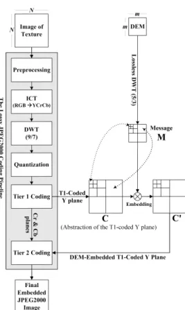
In a typical lossy JPEG2000 pipeline the two key steps with potential loss of data are quantization and tier-1 (T1) cod-ing. These two steps come after the the irreversible color and DWT (9/7) transforms. For the lossless case the quantization is reversible and that is why in the earlier version [3] the in-tervention came immediately after the DWT(5/3) step. For the lossy case we have changed the strategy since quantiza-tion is now inevitable. What we did is to interrupt the flow after the T1 coding as shown in Fig. 1.
2.1 Description of the Method
In T1 coding, which is the first of the two coding stages of JPEG2000, for each subband, the quantized coefficients are partitioned into rectangular code blocks. The nominal di-mensions of a given code block should be dyadic and their product not exceed 4096. The partitioned code blocks are coded independently using the bit-plane coder thus generat-ing a sequence of symbols with some or all of these may be entropy coded2. Due to this independent encoding of code blocks, the correspondence between the lossless DWTed DEM and lossy DWTed Y plane of texture is maintainable. The T1 coded symbols from a given block vary in energy and the low index symbols are more energetic than the higher in-dex ones. What we do is to use the least energetic of these symbols, from the tail of the stream for each code block, for LSB embedding implying non-random allocation. There is, however one problem in that the T1 coded symbols have smaller word size resulting in smaller embedding capacity and higher rate of distortion in quality as a result of embed-ding. This policy is not, however, advised in the lossless case since word sizes of the coefficients are longer at the earlier steps thus leading to lesser distortions as result of embed-ding. Hence one can embed immediately after the DWT step at the earliest.
2.2 The Data Hiding Step
From a N×N pixel texture image and the corresponding map of m2altitudes, we deduce the embedding factor E = m2/N2
coefficients per pixel. The image of texture will, there-fore, have to be divided into square blocks of size equal
2http://www.ece.uvic.ca/
∼mdadams/jasper/
Figure 1: Description of the method
to⌈1/E⌉ pixels and every such block would hide one alti-tude coefficient. In the first place, the T1-coded quantized level L DWTed Y component (say carrier C) of the texture image is extracted from the lossy JPEG2000 pipeline that employs the irreversible Daubechies (9/7) [1]. A discrete wavelet transformation (DWT) is separately applied to the DEM coefficients at the same level L to get the message M, as illustrated in Fig. 1. The implementation of the discrete wavelet transformation (DWT) of the DEM is based on the lifting method [11] that employs the JPEG2000 supported re-versible Daubechies (5/3) [1]. It has been ensured that both
M and C are at the same level of transformation and em-bedding is according to the correspondence of subbands, i.e. lower frequency subbands of cover carry the lower subband coefficients of message as illustrated in Fig. 1. One impor-tant point to mention is that in this work neither any copy-right problem is solved nor is there any threat to the security of message. What we want is to carry out embedding with-out significant loss in the visual quality of the 3D rendering. At the same time, the hiding capacity is also important since day by day the resolution quality is improving at the expense of data size. Hence, of the traditional requirements of data hiding, we are more particular about perceptual transparency and payload which implies that robustness and tamper resis-tance are secondary in imporresis-tance.
To ensure a spatial coherence between the altitudes and the texture, the cover C is partitioned into square blocks of ⌈1/E⌉ coefficients for data embedding and every such block would hide one transformed altitude coefficient of the mes-sage M. We thus achieve a synchronization in the embedding as far as the incremental levels of the wavelets are concerned,
i.e. low resolution coefficients of the altitude map are embed-ded in the low resolution subbands of texture whereas high resolution coefficients of the altitude map are embedded in the high resolution subbands. In this way the transmission of the part concerned with the low resolution of the texture map enables us to directly access the corresponding low res-olution part of the altitude map. For perceptual transparency, an embedding strategy based on least significant bit (LSB) substitution is proposed. The data embedding is carried out by modifying the LSB’s of coefficients of the T1-coded low-est energy symbols resulting in C′. The final encoded image (.jp2) thus carries the DEM coefficients hidden in some T1-coded symbols from the Y component data.
2.3 The Extraction/Reconstruction Step
The above coded image can be utilized like any other JPEG2000 image and sent across any communication chan-nel. The blind decoding is the reverse of the above process. Just before the T1 stage of the JPEG2000 decoder the DEM can be blindly extracted using the above mentioned parti-tioning scheme. All the DEM bits are LSBs of the lowest energy symbols for each of the given code block from the T1-coded quantized DWTed Y component. One advantage of the method is in the fact that the DEM and texture can be reconstructed with even a small subset of the coefficients of the carrier. The resolution scalability of wavelets and the synchronized character of our method enable a 3D visualiza-tion even with fewer than original resoluvisualiza-tion layers as a result of partial or delayed data transfer. The method thus enables to effect visualization from a fraction of data in the form of the lowest subband, of a particular resolution level. It is al-ways possible to stuff 0’s for the higher bands. The idea is to have a 3D visualization utilizing 3L′+1 parts out of the initial 3L + 1 parts (L′≤ L), by stuffing the rest of L−L′parts with 0’s.
3. THE SIMULATION RESULTS
We have applied our method to a 2048× 2048 pixel exam-ple3texture image (Fig. 2.a) and its corresponding DEM of 64 × 64, 16 bit altitudes implying one altitude per 32 × 32 pixel texture block. By adding a suitable header to the DEM it is converted to a gray-scale image (Fig. 2.b) with whiter parts of the image representing high and black parts repre-senting the low altitudes.
(a) (b)
Figure 2: Original data: a) Texture image, b) Corresponding DEM of the texture image.
We chose to subject the texture to lossy JPEG2000 en-coding at L = 5. For the sake of comparison our
refer-3provided by IGN France (http://www.ign.fr/)
ence will be the lossless method reported in [3] wherein the level L transformed DEM coefficients were embedded in the corresponding Y plane texture coefficients. This step is done immediately after the level L DWT step of the lossless JPEG2000 pipeline using a pseudo-random number genera-tor (PRNG) for allocation. The reason for not using the same point of intervention for lossless version has already been ex-plained in Section 2.
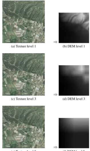
(a) Texture level 1
⇒
(b) DEM level 1
(c) Texture level 3
⇒
(d) DEM level 3
(e) Texture level 5
⇒
(f) DEM level 5
Figure 3: For level 1, 3 and 5 respectively: a), c), e) Re-construction of the approximation image of texture, b), d), f) From the corresponding texture: extraction of the data and reconstruction of DEM.
Level L coded embedded texture image can give L + 1 possible approximation images upon decoding that pertains to resolutions numbered 0, 1, . . . , L in descending order of quality. An L approximate image is constructed from data amounting to 100/4L% of the total coefficients with the rest
of coefficients (missing) being replaced by 0’s before inverse DWT. This is true for all the components. Thus, a level 5 image of approximation is constructed only with 0.1% of the coefficients. Since the data hiding method is synchronous, the level of approximation of both the texture and DEM for a given chunk of available coefficients is the same. Fig. 3.a, c and e show the reconstruction of the images of texture by stuffing 0’s for higher subbands of the level 1, 3 and 5 lowest subbands and inverse DWTing the result to get the images of approximation. From the corresponding textures, level 1, 3 and 5 respectively, we can extract the hidden data and
recon-struct the DEM, as illustrated Fig. 3.b, d and f. One observes that, with a naked eye, degradation in the quality of DEM is more as compared to the texture.
(a)
(b)
Figure 4: a) DEM: RMSE vs Bits per coefficient, b) Texture: MSE vs Bitrate
(a) L′=1 (3.34 bpp) (b) L′=1 (4.20 bpp)
Figure 5: 3D Visualization based on level 1 approxima-tion images from: a) The proposed method, b) Previous method [3].
A quantitative comparison can be done in terms of the images of difference by observing the measures, like MSE or PSNR, as a function of compression rate. It must be noted, that irrespective of the method used, the results are the same as far as the quality of the reconstructed DEM is concerned.
(a) Original (b) L′=0 (10.67 bpp)
(c) L′=2 (0.80 bpp) (d) L′=3 (0.192 bpp)
(e) L′=4 (0.048 bpp) (f) L′=5 (0.012 bpp)
Figure 6: 3D Visualization based on level L′approximation images when level 5 DWTed DEM is embedded in level 5 DWTed texture
Fig. 4.a depicts the trend of these results when√MSEis plot-ted as a function of bits per coefficient for DEM. We have plotted √MSE against bits per coefficient due to the fact that rather than the whole JPEG2000 encoding only DWT has been applied to the DEM coefficients. Since DEM was losslessly DWTed, the resultant quality is the same irrespec-tive of whether the cover Y texture transformed using lossy or lossless DWT before embedding. Fig. 4.b compares the texture quality with MSE for the proposed method with the previous method [3] in function of the bitrate (bpp). It is pertinent to note that for the same bitrate one gets a better quality texture image with the proposed method. For exam-ple, for level 1 extracted and reconstructed texture image, with the previous method [3] one got a PSNR of 31.3 dB and a compression ratio of 5.71. With the proposed method the results are much better because with a PSNR of 31.6 dB we get a compression ratio of 7.19. The 3D visualization with the two methods can be compared by observing Fig. 5. The corresponding 3D visualization images of the original exam-ple and the rest of the levels of approximation in case of the proposed method are given in Fig. 6. It can be seen that even with a very tiny fraction (for example 0.2 bpp for level 3) of data one can have a good visualization.
4. CONCLUSION
In this paper we presented a new method for a scalable 3D terrain visualization through reversible JPEG2000-based blind data hiding. This paper is focused on the topic of data synchronization and scalability. The results reveal that the proposed method offers at least three advantages. First is the synchronized integration of a regular grid of elevations into one whole by the application of data hiding. The second advantage is the scalability in 3D visualization through the utilization of JPEG2000 supported DWT. Last, but not the least, is the integrability of the method with the JPEG2000 encoders to result in a monolithic standalone JPEG2000 for-mat file that eliminates the need to develop any additional technology or data format, thus implying portability and con-formance which is asked by our industrial constraints. In addition the approach is cost effective in terms of memory and bandwidths. The results shown in the case of our exam-ples are witness to this fact since even with a tiny number of coefficients a comparatively better 3D visualization was effected. The resolution scalability of wavelets enables this 3D visualization to improve incrementally with the reception of higher subbands. Besides, this property is helpful in real-time environment when quicker transfer of data is required. The results of 3D visualization simulation give a useful in-sight to the effectiveness of our method in various network conditions.
In the continuation of this work it would be worthwhile to address the fact that loss in quality is not as well marked in the case of texture than in the DEM. Using a desynchronized algorithm, i.e using a subset rather than all of the subbands of Y texture for embedding and lesser DWT decomposition of DEM, would be a good way and should be taken into con-sideration in the near future. It will be important to explore some other embedding strategies, like the spread spectrum embedding, in order to keep DEM quality high for the recon-struction. As far as triangulation is concerned, there is also every likelihood of using a non-uniform grid on various lev-els of details, thus allowing a considerable reduction in the number of triangles necessary for a good representation of the terrain.
5. ACKNOWLEDGMENT
This work was supported in part by the Higher Education Commission (HEC) of Pakistan.
REFERENCES
[1] I. Daubechies and W. Sweldens. Factoring Wavelet Transforms into Lifting Steps. Fourier Anal. Appl., 4(3), 1998.
[2] M. P. Gerlek. The “GeoTIFF Box” Specification for JPEG 2000 Metadata - DRAFT version 0.0. LizardTech, Inc. 1008 Western Ave Suite 200 Seattle, WA 98104 USA, April 2004.
[3] K. Hayat, W. Puech, and G. Gesqui`ere. An Efficient Data-Hiding Method Based on Lossless JPEG2000 for a Scalable and Synchronized Visualization of 3D Ter-rains. In Proc. 15th European Signal Processing
Con-ference (EUSIPCO 07), pages 2519–2523, Poznan, Poland, September 2007.
[4] ISO/IEC. ISO/IEC 15444-1: Information technology,
JPEG2000 image coding system, Part 1: Core
cod-ing system. ISO Central Secretariat: CH-1211 Geneva, Switzerland, 2004.
[5] D. Kundur. Improved Digital Watermarking Through Diversity and Attack Characterization. In Proc. ACM
Workshop on Multimedia Security’99, pages 53–58, Or-lando, FL, USA, Oct. 1999.
[6] D. Kundur and D. Hatzinakos. A Robust Digital Image Watermarking Scheme Using the Wavelet-Based Fu-sion. In Proc. IEEE International Conference on Image
Processing (IEEE ICIP 97), volume 1, pages 544–547, Santa Barbara, CA, USA, Oct. 1997.
[7] D. Kundur and D. Hatzinakos. Digital Watermark-ing UsWatermark-ing Multiresolution Wavelet Decomposition. In
Proc. IEEE International Conference on Acoustic, Speech and Signal Processing (IEEE ICASP 98), vol-ume 5, pages 2969–2972, Seattle, WA, USA., May 1998.
[8] R. Lake, D. Burggraf, M. Kyle, and S. Forde. GML in
JPEG 2000 for Geographic Imagery (GMLJP2) Imple-mentation Specification. Number OGC 05-047r2. Open Geospatial Consortium (OGC), 2005.
[9] J. L. Liu, D. C. Lou, M. C. Chang, and H. K. Tso. A Ro-bust Watermarking Scheme Using Self-Reference Im-age. Computer Standards & Interfaces, 28:356–367, 2006.
[10] F. Losasso and H. Hoppe. Geometry Clipmaps: Terrain Rendering Using Nested Regular Grids. ACM Trans.
Graph., 23(3):769–776, 2004.
[11] S. Mallat. A Wavelet Tour of Signal Processing. Aca-demic Press, 1998.
[12] P. Meerwald. Quantization watermarking in the JPEG2000 coding pipeline. In R. Steinmetz, J. Dittmann, and M. Steinebach, editors, Proc.
Com-munications and Multimedia Security Issues of The New Century, IFIP TC6/TC11 Fifth Joint Working Con-ference on Communications and Multimedia Security, CMS ’01, pages 69–79, May 2001.
[13] P. Meerwald and A. Uhl. A Survey of Wavelet-Domain Watermarking Algorithms. In Proc. SPIE, Electronic
Imaging, Security and Watermarking of Multimedia Contents III, volume 4314, pages 505–516, San Jose, CA, USA, January 2001. SPIE, IS&T.
[14] A. Noore, R. Singh, M. Vatsa, and M. M. Houck. En-hancing Security of Fingerprints through Contextual Biometric Watermarking. Forensic Science Interna-tional, 169(2–3):188–194, 2007.
[15] A. Piva, F. Bartolini, and R. Caldelli. Self Recovery Authentication of Images in The DWT Domain. Int. J.
Image Graphics, 5(1):149–166, 2005.
[16] P. C. Su, H. J. Wang, and C. C. J. Kuo. An Inte-grated Approach to Image Watermarking and JPEG-2000 Compression. Journal of VLSI Signal Processing
Systems, Special Issue on Multimedia Signal Process-ing, 27(1-2):35–53, Jun. 1997.
[17] H. J. Wang and C. C. Kuo. An Integrated Approach to Embedded Image Coding and Watermarking. In Proc.
IEEE International Conference on Acoustic, Speech and Signal Processing (IEEE ICASSP 98), pages 3271– 3275, Seattle, WA, USA, May 1998.
![Figure 5: 3D Visualization based on level 1 approxima- approxima-tion images from: a) The proposed method, b) Previous method [3].](https://thumb-eu.123doks.com/thumbv2/123doknet/14575701.728452/5.918.81.421.169.736/figure-visualization-approxima-approxima-images-proposed-method-previous.webp)