Journal of Craniovertebral
Junction and Spine
J J C V S Editor-in-Chief : Atul Goel (INDIA) Open Access HTML Format
For entire Editorial Board visit : http://www.jcvjs.com/editorialboard.asp
Original Article
Validation protocol for assessing the upper cervical
spine kinematics and helical axis: An in vivo
preliminary analysis for axial rotation, modeling,
and motion representation
Pierre-Michel Dugailly
1,2, Stéphane Sobczak
3, Alphonse Lubansu
3, Marcel Rooze
1,3,
SergeVan Sint Jan
3, Véronique Feipel
1,31Laboratory of Functional Anatomy, Department of Physiotherapy and Rehabilitation, Faculty of Motor Sciences, Free University of Brussels, Brussels,
Belgium, 2Research Unit of Osteopathy, Department of Osteopathic Sciences, Faculty of Motor Sciences, Free University of Brussels, Brussels, Belgium, 3Laboratory of Anatomy, Biomechanics and Organogenesis, Department of Anatomy, Faculty of Medicine, Free University of Brussels, Brussels, Belgium
Corresponding author: Dr. Dugailly Pierre-Michel, Laboratory of Functional Anatomy, Faculty of Motor Sciences (CP619), Université Libre de Bruxelles (ULB), Route de Lennik 808, B-1070 Bruxelles, Belgium. E-mail: [email protected]
Journal of Craniovertebral Junction and Spine 2013, 4:3
Abstract
Context: The function of the upper cervical spine (UCS) is essential in the kinematics of the whole cervical spine. Specifi c motion patterns are described at the UCS during head motions to compensate coupled motions occurring at the lower cervical segments. Aims: First, two methods for computing in vitro UCS discrete motions were compared to assess three-dimensional (3D) kinematics. Secondly, the same protocol was applied to assess the feasibility of the procedure for in vivo settings. Also, this study attempts to expose the use of anatomical modeling for motion representation including helical axis. Settings and Design: UCS motions were assessed to verify the validity of in vitro 3D kinematics and to present an in vivo procedure for evaluating axial rotation. Materials and Methods: In vitro kinematics was sampled using a digitizing technique and computed tomography (CT) for assessing 3D motions during fl exion extension and axial rotation. To evaluate the feasibility of this protocol in
vivo, one asymptomatic volunteer performed an MRI kinematics evaluation of the UCS for axial rotation. Data
processing allowed integrating data into UCS 3D models for motion representation, discrete joint behavior, and motion helical axis determination. Results: Good agreement was observed between the methods with angular displacement differences ranging from 1° to 1.5°. Helical axis data were comparable between both methods with axis orientation differences ranging from 3° to 6°. In vivo assessment of axial rotation showed coherent kinematics data compared to previous studies. Helical axis data were found to be similar between in vitro and in vivo evaluation. Conclusions: The present protocol confi rms agreement of methods and exposes its feasibility to investigate in
vivo UCS kinematics. Moreover, combining motion analysis, helical axis representation, and anatomical modeling,
constitutes an innovative development to provide new insights for understanding motion behaviors of the UCS. Key words: Helical axis, in vivo kinematics, modeling, motion representation, upper cervical spine, validation
INTRODUCTION
Regarding the global kinematics of the cervical spine, the major role of the suboccipital spine (UCS) resides in the completion of specific movements to compensate coupled motions occurring at the lower cervical segments.
Access this article online
Quick Response Code:
Website: www.jcvjs.com
DOI:
Journal of Craniovertebral Junction and Spine 2013, 4:3
In the clinical evaluation of cervical spine function, motion impairments can be demonstrated as both quantitative and qualitative disturbances. Additionally, these kinematic features could be frequently accompanied by pain or discomfort.[1,2]
Examination methods for assessing segmental motion of the cervical spine usually use medical imaging system exposing subject to ionizing radiation such as computed tomography (CT) or radiography.[3-5] Recently, innovative procedures using
magnetic resonance imaging (MRI) have succeeded in analyzing three-dimensional (3D) motions and morphology.[6,7]
For 3D motion analysis, rotation axis orientation is also described to provide qualitative data for kinematics disorders assessment. With regard to the cervical spine, such data are mainly suggested for global head movement[2,8,9] or segmental displacements of the
lower cervical spine.[10] Yet, only few studies have reported such
data in two-dimensional (2D) for the UCS.[11,12]
Despite representative data reported for the in vivo kinematics of the UCS, there is a paucity of studies reporting such data including helical axis computation and motion representation. Th e purpose of this study is to validate a method for assessing UCS 3D motions and to evaluate the feasibility of such a procedure for in vivo conditions. Also, this study att empts to expose the use of anatomical modeling for motion representation including helical axis.
MATERIALS AND METHODS
Kinematics validation method
In the fi rst part of this protocol, one unembalmed human specimen was processed based on a previously described experimental procedure related to UCS kinematics.[13] Aft er soft tissue dissection
and prior to motion assessment, technical markers (TM = aluminum balls, 4 mm diameter) were pasted on the UCS bones (occiput (C0), atlas (C1), and axis (C2)). Discrete motions were considered using diff erent UCS poses of fl exion extension (FE) and axial rotation (AR). Validation was carried out using two diff erent acquisition methods, a digitizing procedure using a 3D digitizer (FARO, B06/Rev 18; Technologies Inc; USA), and CT (Siemens SOMATOM, helical mode, reconstruction: slice thickness = 0.5 mm, interslice spacing = 1 mm, image data format = DICOM 3.0). For each UCS att itude, TMs spatial locations were computed successively from 3D digitizing (TMdig) and CT imaging (TMCT), using a customized experimental jig providing similar control of joint displacements in each method.[14] Five discrete
poses were collected through the entire range of motion in each plane of interest.
Also, to obtain 3D models of all UCS bones (C0, C1, and C2), CT data were processed following a data segmentation procedure using dedicated soft ware (Amira 3.0®, Germany).
In vivo assessment
To evaluate the feasibility of the above protocol, one asymptomatic volunteer (37 years) was selected to perform
an MRI kinematics assessment of the UCS for axial rotation (Philips Achieva 3T MRI, 3 Tesla, Philips Health Care, Best, Th e Netherlands, thickness = 1 mm, fi eld of view = 160 mm, reconstruction pixel size 0.7 × 0.7 mm 2 averages). Motion evaluation was carried out according a method previously developed by Ishii et al.[6] for fi ve UCS discrete positions in AR
from neutral position to maximal physiological active rotation with an intermediate att itude on both sides. Th e subject was in supine position with a head support. For assuring pure axial rotation, the head was held perpendicular to the MRI table under supervision of one operator using the Frankfurt plane as a reference. For each UCS att itude, MRI acquisition lasted 5 min approximately.
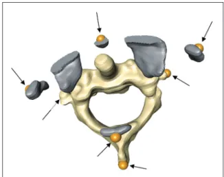
In addition, the volunteer had performed a CT scan evaluation during an earlier clinical routine assessment less than 2 years. Th e latt er examination was not related with cervical complaints. Imaging data (CT and MRI) were processed to create individual anatomical models using the above mentioned soft ware. On each MRI model, anatomical landmarks were defi ned by virtual palpation as represented in Figure 1 to compute discrete kinematics data. Reproducibility of this method is described elsewhere reporting an average palpation error less than 1 mm.[13] CT data was only used to provide accurate 3D UCS
model for motion representation.
Data registration, kinematics and motion
representation
To combine motion visualization of the collected bone segments and their associated discrete kinematics, a registration method was used as described in details previously.[13,15] Registration
was performed using a computer graphics environment, LHP FusionBox soft ware (www.openmaf.org) for providing data fusion. For each bone, motion was computed according its spatial position and orientation within the local anatomical coordinate system as defi ned earlier.[13] Th us C0-C1 and C0-C2 motions were defi ned in
Figure 1: Three-dimensional (3D) atlantoaxial magnetic resonance imaging (MRI) model. Location of technical markers (arrows) following virtual palpation of anatomical landmarks. Model of C1 includes only necessary bone segments
the C1 and C2 reference systems, respectively. From the above data, fi nite helical axis (FHA) parameters (i.e., orientation and position) were determined and integrated into the 3D model to represent axis behavior over the range of motion for each UCS level.
RESULTS
Kinematics validation
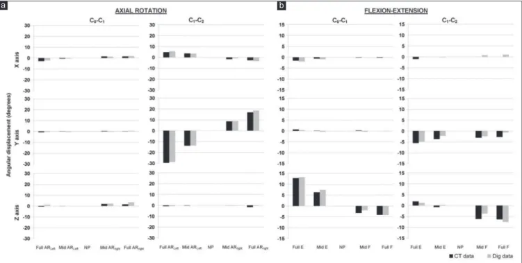
For AR, global C0-C2 range of motion (ROM) was estimated to 52° and 53° according to CT and digitizing measurements, respectively. For FE, maximal amplitude reached 25° and 26°. To evaluate agreement between the motion data, both methods were compared using estimation of absolute diff erence between measurements. Regarding discrete ROM, absolute mean diff erences were less than 1° for AR and ranged from 0.8° to 1.4° for FE. Discrete amplitudes are described in Figure 2 for each segment att itude. Concordance between angular displacements was demonstrated by coeffi cients of determination above 0.84 for rotation magnitudes superior to 1° [Table 1].
Concerning helical axis, orientation, and position were computed for both motions with an exception for C0-C1 AR due to the poor mobility at this level (5°). Absolute diff erences for FHA orientation ranged from 3.5° to 6.4° for C0-C1 FE and C1-C2 AR, respectively. Also for C1-C2 FE, only mean HA was considered due to limited global range of motion (8°). For the latt er, orientation error was found to be less than 5°. As an example, Figure 3 illustrates FHA orientation and location for AR at C1-C2 level for both acquisition methods. Orientation of averaged FHA displayed a diff erence of 3° with a standard deviation (SD) of 1.4°
for both methods. For HA location, a maximal error of less than 1 mm was found regardless to anatomical reference axis.
In vivo assessment
Motion data (angular displacements and translations) are displayed in Table 2 related to AR at C1-C2. Principal angular displacement was observed around the Y-axis with a global magnitude of 71°. Coupled motions were demonstrated around secondary axes (X- and Z-axis) with maximal absolute rotation of 5° and 11°, respectively. For translations, small cephalocaudal and lateral displacements were observed. Figure 4 illustrated individual kinematics patt erns occurring for angular displacements and translations throughout the entire motion range.
Averaged helical axis data (location and orientation) are presented in Table 3 and FHA graphical representation is displayed for three att itudes of C1-C2 AR [Figure 5]. Note the relative constant orientation of FHA aligned with the dens of C2, with an ipsilateral location to the direction of AR. Maximal FHA displacement was observed along the Z-axis with a magnitude of 11 mm for both rotation sides.
Figure 2: Kinematics data for axial rotation (AR) and (a) fl exion extension (FE). (b) Helical angles computation. Representation of angular displacements of C0-C1 and C1-C2 for each discrete position for computed tomography (CT) and digitizing (Dig) measurements. NP=Neutral position
Table 1: Coeffi cients of determination (r2)
between computed tomography (CT) and digitizing kinematics data
C0-C1 C1-C2
θX θY θZ θX θY θZ
FE 0,972 0,919 0,990 0,213§ 0,837 0,854
AR 0,982 0,011§ 0,584§ 0,969 0,999 0,302§
§ indicates discrete range of motion inferior to 1°
Journal of Craniovertebral Junction and Spine 2013, 4:3
Figure 3: Representation of C1-C2 fi nite helical axis (FHA) location and orientation for digitizing (right column) and CT (left column) data between discrete motions (a, b, c, and d) from maximal right to left axial rotation, anterior views
Figure 4: In vivo kinematics data, helical angles ( in degrees) and
(a) translations (t in mm (b) for C1-C2 axial rotation (one single volunteer). Sample polynomial function (goodness of fi t, r2 > 0.87) DISCUSSION
Th e fi rst part of the present study aimed at validating a procedure for assessing the kinematics of the UCS using two diff erent methods for computing bone spatial location. Th is method is based on a previous study proposed by Van Sint Jan et al.,[15]
investigating elbow kinematics. Th e latt er authors observed small motion divergences between comparable methods with maximal diff erences of about 1° for helical rotation. Th ese results agreed with the present outcomes of rotation errors ranging from 1° to 1.5° depending on the level and the motion direction. Moreover, coeffi cients of determination demonstrated a good concordance between methods for helical angles for both motions of interest. Comparatively, earlier methods found angular errors ranging from 1° to 2° at the cervical spine either for global motion[16] or for segmental motion.[17,18]
Additionally, for helical axis orientation and position, the diff erences ranged from 3° to 6°, confi rming good agreement between the methods for measuring UCS kinematics.
For the selected specimen, global ROM was found to be similar to previously reported in vitro data for AR but lesser for FE.[13,19-23] However, for FE several authors reported similar
values for in vivo conditions.[18,24] For in vitro experimental
methods, ROM discrepancies are generally recognized compared to that found for in vivo conditions. Moreover, lower
Table 2: In vivo kinematics data for C1-C2 axial rotation (AR)
Helical angle (°) Position (mm)
x y z x y z
Right AR -2,5 -37,7 -6,1 0,2 -3,1 -1,1
Left AR 4,9 33,7 10,6 -0,4 -1,1 1,1
Helical angles (°) and translation (mm) expressed in the anatomical reference system of C2
Table 3: Mean helical axis orientation (cosines) and position (mm) Orientation Position x y z x y z Mean 0,014 0,999 -0,043 -2,6 0,1 1,6 SD 0,004 0,000 0,009 0,9 0,2 3,7 max 0,020 0,999 -0,028 -0,9 0,3 5,6 min 0,007 0,998 -0,570 -4,1 -0,2 -5,0
Standard deviation (SD), minimal (min), and maximal (max) values
a b c d a b
values could also be observed for some pathological conditions such as degenerative or rheumatoid processes at the UCS.[7]
As mentioned in the literature, coupled motions frequently occur during AR or lateral bending of the UCS. Th ese associated motion components are mainly reported as extension and heterolateral fl exion during AR and as axial rotation (at C1-C2) for lateral bending. Here, coupled motions are mostly found at C1-C2 during fl exion extension with a maximal magnitude around 5°. Such specifi c patt erns have been mentioned earlier for FE[20,25] and some authors linked these phenomena to the
degenerative processes noticed at the UCS.[7]
Th e second part of this work aimed at developing a noninvasive method for investigating the in vivo kinematics of the UCS using MRI acquisition. Based on a previously reported procedure, assessment was performed for fi ve poses, from maximal left to right AR respecting the subject’s comfort.[6,26] Following this
method, UCS axial rotation ROM represents 90% of the head rotation approximately.[26] Kinematics was collected from MRI
data performing virtual palpation of anatomical landmarks using specifi c computer graphic soft ware. Such a method has already been recommended to provide spatial bone location as well as to build anatomical reference system. Using a registration method, kinematics and imaging data were fused to generate an anatomical model including kinematics behavior, HA motion representation as described earlier.[13,15]
For our single volunteer, the global range of motion in AR was found to be similar to the data reported from studies relating
in vivo assessment of the UCS with a value around 71°.[5-7,26]
Moreover, right rotation was slightly larger than left rotation, 37° versus 34°. Th is diff erence could be related either to the manual control of the subject’s head position or to the compliance to rotational stress between upper and lower cervical spine.[6]
Considering coupled motions, our results agreed with the recent data for in vivo conditions.[6,26] In the present study, coupled
lateral fl exion was demonstrated in the opposite direction to AR
with an absolute magnitude ranging from 3° to 5°. For coupled motions in the sagitt al plane, an irregular patt ern was observed with a coupled extension during right rotation and a coupled fl exion in left rotation, of 11° and 6°, respectively. As mentioned above, such motion patt ern has been reported previously. Nevertheless, we must keep in mind that the lack of control of the subject’s head position could be a source for asymmetric att itude in axial rotation[5,6] as well as for the coupled motions.
In this way, alternative methods were developed to standardize head att itude during such assessment.[27,28]
During UCS motion, coupled translations are also reported as well for AR as for FE. Th ese coupled motions are dependent on the measuring methods, but also on the reference system. In consideration for the latt er, anatomical reference systems defi ned in this study are consistent with previous recommendations.[20]
Similar to the validation data, analysis of the in vivo HA shows comparable orientation and location to previously reported data.[13] As pointed out earlier, HA displays a vertical att itude
trough to the dens of the axis during AR with moderate location variations depending on motion direction and subjects.[5,13,29]
Th us, these singular outcomes show meaningful data regarding quantitative and qualitative in vivo kinematics compared to aforementioned in vitro data. Nevertheless, limitations of this study include the need of investigation for assessing reliability in a large sample before starting functional evaluation of UCS as clinical routine.
In conclusion, the protocol presented here confi rms agreement of motion measurements and exposes its feasibility to investigate
in vivo UCS kinematics. Moreover, combining motion analysis,
helical axis representation and anatomical modeling, such innovative development provides new insights for understanding normal and abnormal motion behaviors of the UCS. Further investigations are now being started to integrate this method to evaluate other UCS motion types as well as the lower cervical spine kinematics.
REFERENCES
1. Feipel V, Rondelet B, LePallec JP, DeWitte O, Rooze M. The use of disharmonic motion curves in problems of the cervical spine. Int Orthop 1999;23:205-9. 2. Grip H, Sundelin G, Gerdle B, Karlsson JS. Variations in the axis of motion during head repositioning — a comparison of subjects with whiplash-associated disorders or non-specifi c neck pain and healthy controls. Clin Biomech (Bristol) 2007;22:865-73.
3. Dvorak J, Hayek J, Zehnder R. Ct-functional diagnostics of the rotatory instability of the upper cervical spine Part 2. An evaluation on healthy adults and patients with suspected instability. Spine (Phila Pa 1976) 1987;12:726-31. 4. Dvorak J, Panjabi MM, Hayek J. Diagnosis of hyper- and hypomotility of the
upper cervical spine using functional computerized tomography. Orthopade 1987;16:13-9.
5. Iai H, Moriya H, Goto S, Takahashi K, Yamagata M, Tamaki T. Three-dimensional motion analysis of the upper cervical spine during axial rotation. Spine (Phila Pa 1976) 1993;18:2388-92.
6. Ishii T, Mukai Y, Hosono N, Sakaura H, Nakajima Y, Sato Y, et al. Kinematics of the upper cervical spine in rotation: In vivo three-dimensional analysis. Spine (Phila Pa 1976) 2004;29:E139-44.
7. Takatori R, Tokunaga D, Hase H, Mikami Y, Ikeda T, Harada T, et al. Three-dimensional morphology and kinematics of the craniovertebral junction in rheumatoid arthritis. Spine (Phila Pa 1976) 2010;35:E1278-84.
Figure 5: Atlantoaxial 3D-model and helical axis (HA) orientation and location during axial rotation in vivo. Superior view and posterior view for three discrete positions. NP=Neutral position
Journal of Craniovertebral Junction and Spine 2013, 4:3
8. Grip H, Sundelin G, Gerdle B, Stefan Karlsson J. Cervical helical axis characteristics and its center of rotation during active head and upper arm movements-comparisons of whiplash-associated disorders, non-specifi c neck pain and asymptomatic individuals. J Biomech 2008;41:2799-805.
9. Woltring HJ, Long K, Osterbauer PJ, Fuhr AW. Instantaneous helical axis estimation from 3-D video data in neck kinematics for whiplash diagnostics. J Biomech 1994;27:1415-32.
10. Cripton PA, Sati M, Orr TE, Bourquin Y, Dumas GA, Nolte LP. Animation of in vitro biomechanical tests. J Biomech 2001;34:1091-6.
11. Fuss FK. Sagittal kinematics of the cervical spine — How constant are the motor axes? Acta Anat (Basel) 1991;141:93-6.
12. Van Mameren H, Sanches H, Beursgens J, Drukker J. Cervical spine motion in the sagittal plane. II. Position of segmental averaged instantaneous centers of rotation — A cineradiographic study. Spine (Phila Pa 1976) 1992;17:467-74.
13. Dugailly PM, Sobczak S, Sholukha V, Van Sint Jan S, Salvia P, Feipel V, et al. In vitro 3D-kinematics of the upper cervical spine: Helical axis and simulation for axial rotation and fl exion extension. Surg Radiol Anat 2010;32:141-51. 14. Dugailly PM, Sobczak S, Moiseev F, Sholukha V, Salvia P, Feipel V, et al.
Musculoskeletal modeling of the suboccipital spine: Kinematics analysis, muscle lengths and muscle moment arms during axial rotation and fl exion extension. Spine (Phila Pa 1976) 2011;36:E413-22.
15. Van Sint Jan S, Salvia P, Hilal I, Sholukha V, Rooze M, Clapworthy G. Registration of 6-DOFs electrogoniometry and CT medical imaging for 3D joint modeling. J Biomech 2002;35:1475-84.
16. Tousignant M, Smeesters C, Breton AM, Breton E, Corriveau H. Criterion validity study of the cervical range of motion (CROM) device for rotational range of motion on healthy adults. J Orthop Sports Phys Ther 2006;36:242-8. 17. Anderst WJ, Baillargeon E, Donaldson WF 3rd, Lee JY, Kang JD. Validation of a noninvasive technique to precisely measure in vivo three-dimensional cervical spine movement. Spine (Phila Pa 1976) 2011;36:E393-400.
18. Frobin W, Leivseth G, Biggemann M, Brinckmann P. Sagittal plane segmental motion of the cervical spine. A new precision measurement protocol and normal motion data of healthy adults. Clin Biomech 2002;17:21-31. 19. Cattrysse E, Baeyens JP, Clarys JP, Van Roy P. Manual fixation versus
locking during upper cervical segmental mobilization. Part 2: An in vitro three-dimensional arthrokinematic analysis of manual axial rotation and lateral bending mobilization of the atlanto-axial joint. Man Ther 2007;12:353-62.
20. Cattrysse E, Baeyens JP, Clarys JP, Van Roy P. Manual fi xation versus locking during upper cervical segmental mobilization. Part 1: An in vitro three-dimensional arthrokinematic analysis of manual fl exion-extension mobilization of the atlanto-occipital joint. Man Ther 2007;12:342-52.
21. Chancey VC, Ottaviano D, Myers BS, Nightingale RW. A kinematic and anthropometric study of the upper cervical spine and the occipital condyles. J Biomech 2007;40:1953-9.
22. Chin KH, Tan KW, Goh JC, Toh SL, Lee VS. 2003. Flexibility testing of the human upper cervical spine under continuous loading and unloading. Proceeding of the Summer Bioengineering Conference, Key Biscayne, Florida 2003;1185-6. 23. Kettler A, Hartwig E, Schultheiss M, Claes L, Wilke HJ. Mechanically simulated muscle forces strongly stabilize intact and injured upper cervical spine specimens. J Biomech 2002;35:339-46.
24. Karhu JO, Parkkola RK, Koskinen SK. Evaluation of fl exion/extension of the upper cervical spine in patients with rheumatoid arthritis: An MRI study with a dedicated positioning device compared to conventional radiographs. Acta Radiol 2005;46:55-66.
25. Amiri M, Jull G, Bullock-Saxton J. Measuring range of active cervical rotation in a position of full head fl exion using the 3D Fastrak measurement system: An intra-tester reliability study. Man Ther 2003;8:176-9.
26. Nagamoto Y, Ishii T, Sakaura H, Iwasaki M, Moritomo H, Kashii M, et al. In Vivo three-dimensional kinematics of the cervical spine during head rotation in patients with cervical spondylosis. Spine (Phila Pa 1976) 2011;36:778-83. 27. Karhu JO, Parkkola RK, Komu ME, Kormano MJ, Koskinen SK. Kinematic
magnetic resonance imaging of the upper cervical spine using a novel positioning device. Spine (Phila Pa 1976) 1999;24:2046-56.
28. Ishii T, Mukai Y, Hosono N, Sakaura H, Fujii R, Nakajima Y, et al. Kinematics of the cervical spine in lateral bending: In vivo three-dimensional analysis. Spine (Phila Pa 1976) 2006;31:155-60.
29. Roche CJ, King SJ, Dangerfi eld PH, Carty HM. The atlanto-axial joint: Physiological range of rotation on MRI and CT. Clin Radiol 2002;57:103-8. How to cite this article: Dugailly P, Sobczak S, Lubansu A, Rooze M,
Jan SS, Feipel V. Validation protocol for assessing the upper cervical spine kinematics and helical axis: An in vivo preliminary analysis for axial rotation, modeling, and motion representation. J Craniovert Jun Spine 2013;4:10-5.
Source of Support: Nil, Confl ict of Interest: None declared.
New features on the journal’s website Optimized content for mobile and hand-held devices
HTML pages have been optimized of mobile and other hand-held devices (such as iPad, Kindle, iPod) for faster browsing speed. Click on [Mobile Full text] from Table of Contents page.
This is simple HTML version for faster download on mobiles (if viewed on desktop, it will be automatically redirected to full HTML version)
E-Pub for hand-held devices
EPUB is an open e-book standard recommended by The International Digital Publishing Forum which is designed for reflowable content i.e. the text display can be optimized for a particular display device.
Click on [EPub] from Table of Contents page.
There are various e-Pub readers such as for Windows: Digital Editions, OS X: Calibre/Bookworm, iPhone/iPod Touch/iPad: Stanza, and Linux: Calibre/Bookworm.
E-Book for desktop
One can also see the entire issue as printed here in a ‘flip book’ version on desktops. Links are available from Current Issue as well as Archives pages.