RESEARCH OUTPUTS / RÉSULTATS DE RECHERCHE
Author(s) - Auteur(s) :
Publication date - Date de publication :
Permanent link - Permalien :
Rights / License - Licence de droit d’auteur :
Bibliothèque Universitaire Moretus Plantin
Institutional Repository - Research Portal
Dépôt Institutionnel - Portail de la Recherche
researchportal.unamur.be
University of Namur
Feature Diagrams for Change-Oriented Programming
Ebraert, Peter; Classen, Andreas; Heymans, Patrick; D'Hondt, Theo
Published in:Proceedings of the 10th International Conference on Feature Interactions (ICFI'09), Lisbon, Portugal
Publication date:
2009
Document Version
Early version, also known as pre-print
Link to publication
Citation for pulished version (HARVARD):
Ebraert, P, Classen, A, Heymans, P & D'Hondt, T 2009, Feature Diagrams for Change-Oriented Programming. in M Nakamura & S Reiff-Marganiec (eds), Proceedings of the 10th International Conference on Feature
Interactions (ICFI'09), Lisbon, Portugal. IOS Press, Amsterdam, pp. 107-122.
General rights
Copyright and moral rights for the publications made accessible in the public portal are retained by the authors and/or other copyright owners and it is a condition of accessing publications that users recognise and abide by the legal requirements associated with these rights. • Users may download and print one copy of any publication from the public portal for the purpose of private study or research. • You may not further distribute the material or use it for any profit-making activity or commercial gain
• You may freely distribute the URL identifying the publication in the public portal ?
Take down policy
If you believe that this document breaches copyright please contact us providing details, and we will remove access to the work immediately and investigate your claim.
Feature Diagrams for Change-Oriented
Programming
Peter EBRAERTaAndreas CLASSENb,1Patrick HEYMANSbTheo D’HONDTa aComputer Science Department, Vrije Universiteit Brussel,
1050 Brussels, Belgium,{pebraert,tjdhondt}@vub.ac.be
bPReCISE Research Centre, Faculty of Computer Science, University of Namur,
5000 Namur, Belgium,{acs,phe}@info.fundp.ac.be
In Proceedings of the 10th International Conference on Feature Interactions in Software and Communication Systems (ICFI’09) held in conjunction with Distributed Computing Techniques 2009 (DisCoTec’09), Lisbon, Portugal, June 2009.
Abstract. The idea of feature-oriented programming is to map requirements to fea-tures, concepts that can be composed to form a software product. Change-oriented programming (ChOP), in which features are seen as sets of changes that can be applied to a base program, has recently been proposed as an approach to FOP. Changes are recorded as the programmer works and can encapsulate any developer action, including the removing of code.
Before changes can be combined to form a product, it has to be verified that there are no harmful interactions between selected changes. There exists, however, no formal model of the current approach that may serve as a reference specification for ChOP implementations. In an effort to fill this gap, we propose a formal model of ChOP, which, as we will show, maps to the well-understood notion of feature di-agram. Thanks to this, we can reuse a number of results in feature diagram research and apply them to ChOP.
Keywords. Formal Methods, Feature-Oriented Programming, Feature Diagrams, Software Product Lines
1. Introduction
Software Product Line Engineering(SPLE) is a software engineering paradigm that in-stitutionalises reuse throughout software development. Central to SPLE is the manage-ment of variability, i.e. “the commonalities and differences in the applications in terms of requirements, architecture, components, and test artefacts” [1].
Several methods for implementing variability in SPLE exist [2]. Traditional ap-proaches sometimes lack modularity and reusability [3] or require a significant amount of manual labour [4]. Feature-Oriented Programming (FOP) overcomes these problems by using features as first-class abstractions during the development process [5,6,7]. A feature closely maps to a variant of a variable requirement and variability can be imple-mented merely by selecting or deselecting features. In Change-Oriented Programming (ChOP), a specific approach to FOP, each feature is represented by a set of changes ap-plied to a base system [8,9]. Feature composition, in this case, becomes change com-position. One of the challenges in ChOP is to make sure that a composition of several
features, viz. changes, is free of harmful interactions: two or more changes that must be applied together for a composition to be valid. However, there is currently no formal framework for ChOP, that would allow to define this kind of property and serve as a reference for ChOP implementations.
In an effort to fill this gap, we propose a formal model of ChOP. First, we formalise its concepts and properties using common set theory. Then, we show how our implemen-tation of ChOP conforms to the formal model. Furthermore, we define properties such as composabilityof a set of changes, that need to be checked before they can be composed. An interesting observation is that the model is quite close to Feature Diagrams (FD), a SPLE notation used to model the variability and manage the interactions of an appli-cation at an – up to now – relatively high level of granularity [10,11,12,13]. The main purpose of FDs it to model which combinations of features are allowed and disallowed in a software product line. By mapping the formal model of ChOP to FDs, we are able to reuse their well-studied semantics as well as existing analysis tools. We prove that composabilityof features in ChOP is equivalent to checking whether the product they form satisfies the FD.
The paper is structured as follows. Section 2 recalls the concepts of FOP and ChOP, while Section 3 remembers the definition of FDs. Section 4 introduces a formal model for ChOP, which is mapped to FDs in Section 5. The paper is concluded in Section 6 with a discussion on future work.
2. Feature and change-oriented programming
FOP is a programming paradigm that targets the separation of concerns [14]. In FOP, every concern is modularised as a separate feature: a first-class entity that forms the basic building block of a software system [6]. Features satisfy intuitive user-formulated requirements on the software system and can be composed to form different variations of the same system [15].
Most state-of-the-art approaches to FOP specify a feature as a set of building blocks. An alternative, already pointed out by Batory in [6], is to see a feature as a function that modifies a program, so that feature composition becomes function composition. Indeed, a feature would be seen as a function prog → prog that takes a program, modifies it by adding the functionality that implements the feature’s requirement, and returns the modified program. The application of a feature to a program yields a new program, ex-tended by that feature, to which in turn some other feature can be applied. In that view, a system is obtained by applying a sequence of features to a base program. The AHEAD toolchain [7] was recently formalised this way [5].
In [8] and [9] we proposed ChOP, a novel incarnation of FOP, that uses change as the main development entity.
2.1. Change-oriented programming
The central idea of ChOP is that a system can be specified by a set of first-class change objects, which represent the development actions that were (or have to be) taken in order to produce it. There are several ways of obtaining these change objects. A classic way is to take two finished versions of a software system and to execute a Unix diff
com-class Buffer { int buf = 0; int get() { return( buf ); }
void set( int x ) { buf = x; } } B1 B2 B3 B5 B4 B6 class Buffer { int buf = 0; int back = 0; int get() { return( buf ); }
void set( int x ) { back = buf; buf = x; } void restore() { buf = back; } } R1 R2 R3 R4 class Buffer { int buf = 0; int back = 0; int get() { logit(); return( buf ); }
void set( int x ) { logit(); back = buf; buf = x; } void restore() { logit(); buf = back; } void logit() { print(back); print(buf); } } L1 L5 L6 L2 L3 L4 class Buffer { int buf = 0;
Stack back = Stack new();
int get() { logit(); return( buf ); }
void set( int x ) { logit(); back.push(x); buf = x; } void restore() { logit(); buf = back.pop(); } void logit() { print(back.top()); print(buf); } } M4 M6 M1 M2M3 M5 Logging R1 R2 R3 R4 Restore B1 B2 B3 B1 B2 B3 L1 L6 L5 L2 L3 L4 R1 R2 B5 B3 B1 B2 B5 B4 B6 Mul. Res M4 M6 M1 M2 M3 M5 R1 R3 R4 L5 Buffer Buffer B2 B1 B4 B3 B6 B5 Restore Logging R1 R2 R4 R3 Mul. Res M4 M6 M1 M2 M3 M5 InvokeLog LogMethod PrintInstVars L1 L6 L5 L2 L3 L4 Log Method PrintInstVars InvokeLog
Figure 1. Buffer: (left) source (right) change objects
mand on their respective abstract syntax trees [16], revealing the changes. This approach, however, only works a posteriori, and at a high level of granularity (the version level). A more subtle alternative is to log the developer’s actions as he is performing the changes. This can be done, for instance, by taping into the IDE, and extending it with a mechanism that captures the developer actions and stores them as change objects. In [8,9], we opted for the latter approach since it provides a more complete overview of all development actions [17].
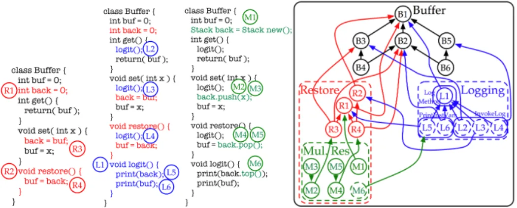
Figure 1 shows the source code of a Buf f er class on the left, and a diagram on the right. As mentioned before, a feature in ChOP is a set of change objects, representing the incremental development actions taken to implement it. It is drawn as a rectangle with rounded corners, a name, and change objects inside it. The example consists of the sole feature Buf f er. Each change object has a unique ID drawn inside a circle: B1 is a change that creates the class, B4 and B3 add an accessor for the instance variable buf , and so on. To make the example more intuitive, the code is annotated with the IDs of the change objects to indicate in what they consist. The arrows between change objects denote structural dependencies. For instance, B4 depends on the change that adds the method itself (viz. B3) and on the change that adds the instance variable that it accesses (viz. B2). These structural dependencies stem from the programming language used, and reflect its grammar (e.g. a statement must be inside a method) and static seman-tics (e.g. a variable must exist in the scope in which it is used). A diagram of features, changes and structural dependencies is called a change specification. It can be annotated by the developer with arrows that denote semantical dependencies stemming from do-main knowledge. Both structural and semantical dependencies make explicit that the de-pending change cannot be applied without applying the dependent change. Dependencies represent the interaction between the change objects and can be used to detect anomalies in the composition of software variations which we call harmful interactions.
Continuing with the illustration, Figure 2 shows how the Buf f er class is gradually extended with three more features: Restore, Logging, and M ultipleRestore. The re-store feature rere-stores the value of the buffer, the logging feature logs the values of all instance variables whenever a method of the buffer is executed, and the multiple restore feature allows the buffer to restore more than one value. The upper half of Figure 2 shows the annotated code, while the lower half shows the change specification. As can be seen in the change specification, features can be nested by drawing them inside another. In addition, sub-features and changes can be optional or mandatory, where optionality is de-noted by a dashed border. When a nested feature is applied to a system, all its mandatory sub-features and changes have to be applied as well, whereas optional ones may be left out. Take, for instance, the Logging feature. Indeed, its implementation can be broken down into three distinct activities: (1) a method logit needs to be created, (2) it needs to be filled with print statements for all instance variables, and (3) it has to be called in all methods of Buf f er, resulting in three sub-features LogM ethod, P rintInstV ars and
class Buffer { int buf = 0; int get() { return( buf ); }
void set( int x ) { buf = x; } } B1 B2 B3 B5 B4 B6 class Buffer { int buf = 0; int back = 0; int get() { return( buf ); }
void set( int x ) { back = buf; buf = x; } void restore() { buf = back; } } R1 R2 R3 R4 class Buffer { int buf = 0; int back = 0; int get() { logit(); return( buf ); }
void set( int x ) { logit(); back = buf; buf = x; } void restore() { logit(); buf = back; } void logit() { print(back); print(buf); } } L1 L5 L6 L2 L3 L4 class Buffer { int buf = 0;
Stack back = Stack new();
int get() { logit(); return( buf ); }
void set( int x ) { logit(); back.push(x); buf = x; } void restore() { logit(); buf = back.pop(); } void logit() { print(back.top()); print(buf); } } M4 M6 M1 M2M3 M5 class Buffer { int buf = 0; int get() { return( buf ); }
void set( int x ) { buf = x; } } B1 B2 B3 B5 B4 B6 class Buffer { int buf = 0; int back = 0; int get() { return( buf ); }
void set( int x ) { back = buf; buf = x; } void restore() { buf = back; } } R1 R2 R3 R4 class Buffer { int buf = 0; int back = 0; int get() { logit(); return( buf ); }
void set( int x ) { logit(); back = buf; buf = x; } void restore() { logit(); buf = back; } void logit() { print(back); print(buf); } } L1 L5 L6 L2 L3 L4 class Buffer { int buf = 0;
Stack back = Stack new();
int get() { logit(); return( buf ); }
void set( int x ) { logit(); back.push(x); buf = x; } void restore() { logit(); buf = back.pop(); } void logit() { print(back.top()); print(buf); } } M4 M6 M1 M2M3 M5
Figure 2. Left to right: source of Restore, Logging, and M ultipleRestore and the change specification
apply undo Add apply undo Modify apply undo Remove add remove modify Subject sourceAnchor commentsAt FamixObject ... changes apply undo Composite Change apply undo timeStamp isApplied intent user Change D changeSubject affectingChanges feature composites apply undo id Feature apply undo Atomic Change cardinality F4C cardinality Sub parent sons
Figure 3. ChEOPS - Core Model
InvokeLog respectively. They are all mandatory wrt. Logging, whereas the changes inside P rintInstV ars and InvokeLog are not. This is because they are only needed when one of the logged variables, introduced by the other features, exists.
2.2. Proof-of-concept implementation
ChEOPS (Change and evolution-oriented programming support) is an IDE plugin for Vi-sualWorks, which was created as a proof-of-concept implementation of ChOP. ChEOPS fully supports ChOP but also has the capability of logging developers producing code in the standard object-oriented way. Behind the scenes, ChEOPS produces fine-grained first-class change objects that represent the development actions taken by the developer. The UML class diagram of the tool’s core is presented in Figure 3.
We identify three possible actions a developer can take to produce software systems: the addition, the removal and the modification of code. We model them with the classes Add, Remove and Modify respectively. The Atomic Change class plays the role of the abstract Command class in the Command design pattern. A Composite Change is composed of Changes (which can in their turn be of any change kind), that have to be applied as a transaction.
The structural dependency relation between changes is modelled by D: a circular many-to-many relationship on Change. Features are modelled by the Feature class.
Buffer Restore Logging Mul. Res Invoke Log LogMe thod PrintInst Vars Figure 4. Buffer FD
Featureis a class that has a unique name, a set of changes of which it consists and possibly a parent and sons features. The relation between features and the changes of which they consist is modeled by the F 4C relation, which has a cardinality that denotes whether the change is mandatory or optional with respect to the feature. The relation between features is modeled by the Sub relation, that has a parent a son and a cardinality that denotes whether the son is mandatory or not with respect to its parent.
The Subject of a change is a building block of the programming language used to develop the software system. The different building blocks of a programming language are specified by the meta-model of that programming language. As a meta-model, we choose the FAMOOS Information Exchange model because (a) it allows the expression of building blocks up to the statement level and (b) it provides a generic model to which most class-based programming languages (e.g. Java, C++, Ada, Smalltalk) adhere [18, 19].
3. Feature Diagrams
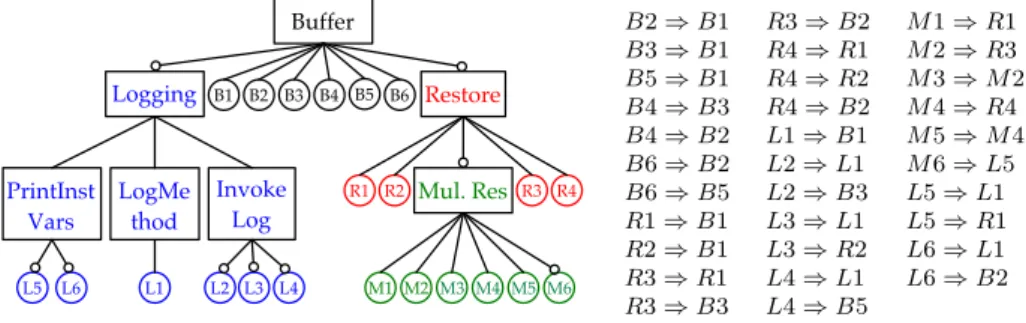
FDs were introduced by Kang et al. as part of the FODA method [10], and have become one of the standard modelling languages for variability in SPLE [1]. An example FD, based on the buffer example, is shown in Figure 4.
Basically, an FD is a hierarchy of features, where the hierarchy relation denotes de-composition. The FD represents the set of allowed feature combinations (called configu-rations), thus a set of sets of features, and several types of decomposition operators de-termine what is allowed and what not. An and decomposition, for instance, means that all child-features need to be included in a configuration if their parent is, while an or decomposition requires at least one child-feature to be included. These two decompo-sition types can be represented with a generic cardinality decompodecompo-sition hi..ji where i indicates the minimum number of children required in a configuration and j the maxi-mum. Some authors also consider optional features, generally represented with a hollow circle above them, which need not be included in a configuration, even if mandated by the decomposition operator. In addition to the decomposition operators, an FD can be an-notated by constraints in a textual language, such as propositional logic [11], that further restrain the set of allowed configurations.
A number of FD dialects have appeared in the literature since their original pro-posal [13]. In this paper, we use the visual syntax of Czarnecki and Eisenecker [20], and the formal semantics of Schobbens et al. [13] which we recall in the following defini-tions.
Definition 1 (FD Abstract Syntax). an FD d is a 6-tuple (N, P, r, λ, DE, Φ) where: • N is the (non empty) set of features (or nodes),
• P ⊆ N is the set of primitive features (i.e. those considered relevant by the modeller),
• r ∈ N is the root,
• DE ⊆ N × N is the decomposition (hierarchy) relation between features. For convenience, we will writen → n0sometimes instead of(n, n0) ∈ DE.
• λ : N → N × N indicates the decomposition operator of a feature, represented as a cardinalityhi..ji where i indicates the minimum number of children required in a configuration andj the maximum (we use angle brackets to distinguish car-dinalities from other tuples).
• Φ ∈ B(N) is a propositional logic formula over the features N, expressing addi-tional constraints on the diagram.
Furthermore, eachd must satisfy the following well-formedness rules: • r is the root ∀n ∈ N (@n0 ∈ N • n → n0) ⇔ n = r,
• DE is acyclic @n1, .., nk ∈ N • n1→ .. → nk → n1,
• Terminal nodes are h0..0i decomposed.
Definition 2 (FD Semantics). Given an FD d, its semantics [[d]] is the set of all valid feature combinations F C ∈ PPN restricted to primitive features: [[d]] = {c ∩ P |c ∈ F C}, where the valid feature combinations F C of d are those c ∈ PN that:
• contain the root: r ∈ c; • satisfy the decomposition type:
f ∈ c ∧ λ(f ) = hm..ni ⇒ m ≤ |{g|g ∈ c ∧ f → g}| ≤ n; • include each selected feature’s parent: g ∈ c ∧ f → g ⇒ f ∈ c; • satisfy the additional constraints: c |= Φ.
The semantics of the diagram in Figure 4 is the set
˘{Buf f er},
{Buf f er, Logging, P rintInstV ars, LogM ethod, InvokeLog}, {Buf f er, Restore},
{Buf f er, Restore, M ul.Res},
{Buf f er, Logging, P rintInstV ars, LogM ethod, InvokeLog, Restore},
{Buf f er, Logging, P rintInstV ars, LogM ethod, InvokeLog, Restore, M ul.Res}¯
For the remainder of the paper, unless otherwise stated, we always assume d to denote an FD, and (N, r, λ, DE, Φ) to denote the respective elements of its abstract syntax.
4. A formal model for ChOP
In this section, we first provide a formal model of the intuitive notions of ChOP presented in Section 2.1 and define some basic properties such as composability. We then show that our tool implementation satisfies the formal model.
4.1. Fundamental concepts
The principal concept in ChOP is the change object, which encapsulates a development operation. A change can be applied to a software system in order to execute the devel-opment operation it encapsulates. Let C be the set of all change objects that make up the system. Another important concept is that of a feature, so let F denote the set of all features fi in the system. As seen in Section 2.1, features consist of changes and can
have sub-features.
First, consider the sub-feature relation. A feature fi can consist of sub-features,
which can each be mandatory (man) or optional (opt), as captured by the relation Sub Sub ⊆ F × F × {man, opt}, (1) where the first element denotes the parent feature and the second the child. For conve-nience, we will note
f1 man → f2if (f1, f2, man) ∈ Sub f1 opt → f2 if (f1, f2, opt) ∈ Sub f1 ?
→ f2 if (f1, f2, man) ∈ Sub ∨ (f1, f2, opt) ∈ Sub.
The relation Sub needs to satisfy two well-formedness constraints. • A sub-feature is either mandatory or optional.
∀f1, f2∈ F • ¬(f1 man
→ f2∧ f1 opt
→ f2) (2)
• The relation contains no cycles, and each feature has no more then one parent. {(f1, f2)|f1
?
→ f2} forms a forest (3)
Then, a feature generally consists of changes c ∈ C which can also be mandatory (man) or optional (opt). This is formalised with the function F 4C
F 4C : C → F × {man, opt}, (4) which associates to each change its parent feature. For convenience, we will note
f man→ c if F 4C(c) = (f, man) f opt→ c if F 4C(c) = (f, opt)
f → c if F 4C(c) = (f, man) ∨ F 4C(c) = (f, opt).?
The structural dependencies between changes, finally, are denoted by the relation D, D ⊆ C × C, (5) which is required to be irreflexive (a change does not depend on itself), asymmetric (changes cannot be mutually dependent) and transitive. In other words, D is a strict partial order over C.
In addition to the well-formedness constraints on Sub, we require that each feature must have sub-features, changes or both.
∀f ∈ F • (∃f0∈ F • f ?
→ f0) ∨ (∃c ∈ C • f ?
→ c) (6) Considered together, all these concepts make up a change specification as the fol-lowing definition records.
Definition 3 (Change specification). A change specification Cs is a 5-tuple Cs = (C, F, Sub, F 4C, D), where C, F, Sub, F 4C and D are as defined above.
4.2. Properties
From the fundamental concepts, we can now define properties that may be required in certain circumstances. Let us first define what a change composition is.
Definition 4 (Change composition). A change composition is a set of changes H ⊆ C (withH 6= ∅) that may be applied to a base system.
Definition 5 (Legal change composition, legal feature set). A legal change composition H is a change composition such that there exists a legal feature set G ⊆ F , which satisfies the following constraints
• If a feature is selected, its parent feature must be selected, too
∀f ∈ G • r→ f =⇒ r ∈ G? (7) • If a feature with mandatory sub-features is selected, those need to be selected, too ∀r ∈ G • rman→ f =⇒ f ∈ G (8) • Let M = {c|f ∈ G ∧ f man→ c}, the set of mandatory changes and O = {c|f ∈
G ∧ f opt→ c}, the set of optional changes. We need that
∗ all changes that are mandatory wrt. the selected features are in: M ⊆ H ∗ all changes stem from selected features: H \ M ⊆ O
• All structural dependencies are satisfied
∀c ∈ H • ∃c0• (c, c0) ∈ D =⇒ c0∈ H (9) By extension, we will say that such a G is a legal feature set for H wrt Cs; or that the changes H are composable. Intuitively, H is the set of features in which the changes of G are contained (through F 4C).
Definition 6 (Semantics of a change specification). The semantics of a change specifica-tion Cs, noted [[Cs]], is defined as the set of pairs (H, G) such that H is a legal change composition ofCs and G is a legal feature set for H wrt Cs according to the above definition.
The following theorem establishes that every change specification has at least one legal change composition, i.e. [[Cs]] 6= ∅ for every change specification Cs. The proofs for this and subsequent theorems were omitted from this paper due to space restrictions, but will be included in the PhD dissertation of the first author.
Theorem 7 (Legal composition existence). For each change specification Cs, there is at least one legal change composition and feature set, i.e.[[Cs]] 6= ∅.
Given a legal feature set G, there might be several legal change compositions. And similarly, given a legal change composition H, there can be several legal feature sets such that (H, G) ∈ [[Cs]]. For proving this, simply consider the following example. Let us assume we have a Cs with only f opt→ f0, f man
→ c and f0 opt→ c0. In this case, we have
[[Cs]] = {({c}, {f }), ({c}, {f, f0}), ({c, c0}, {f, f0})}.
Consequently, we will define the notions of minimal and maximal change composi-tions and prove their uniqueness.
Definition 8 (Minimal/maximal change composition). Given H, G and Cs such that (H, G) ∈ [[Cs]], H is said to be minimal (resp. maximal) if @H0 · H0 ⊂ (resp. ⊃)
H ∧ (H0, G) ∈ [[Cs]].
In the small example we just gave, {c} is both the minimal and maximal change composition wrt {f }, whereas wrt {f, f0}, we have a minimal change composition {c} and a maximal change composition {c, c0}. The following theorem proves the uniqueness of the minimal and maximal change composition in the general case.
Theorem 9 (Uniqueness of minimal and maximal change compositions). A minimal change composition is unique. And so is a maximal change composition.
Similarly, we can define the notions of minimal and maximal feature set.
Definition 10 (Minimal/maximal feature set). Given H, G and Cs such that (H, G) ∈ [[Cs]], G is said to be minimal (resp. maximal) if @G0·G0⊂ (resp. ⊃) G∧(H, G0) ∈ [[Cs]].
Theorem 11 (Uniqueness of minimal and maximal feature sets). A minimal feature set is unique. And so is a maximal feature set.
4.3. ChEOPS
Let us show how ChEOPS, the tool introduced in Section 2.2, is capable of producing change specifications that adhere to Definition 3.
The principal functionality of ChEOPS is to capture the development actions per-formed within VisualWorks and to reify them into instances of the Change class. The set of all those instances corresponds to the set C of the formal model. Once changes are collected, ChEOPS takes changes that belong together and uses them to generate an instance of the Feature class. The set of all those instances maps to the set F of the formal model, and the grouping of changes into features to the F 4C function (Equa-tion 4). The grouping rela(Equa-tion is a func(Equa-tion, since ChEOPS makes sure that every change belongs to exactly one feature. In the current version, ChEOPS actually implements a slightly stricter F 4C, since it requires that the changes of a feature are either all optional
or all mandatory, namely F 4C with property ∀c, c0 ∈ C •F 4C(c) = (f, x)∧F 4C(c0) =
(f, y) ⇒ x = y.
ChEOPS has an interface that allows a developer to group features into more high-level features. The grouping relation actually maps to Sub (Equation 1) of the formal model, in which a parent feature is related to a child feature, which is either mandatory or optional with respect to its parent. The Sub relation implemented by ChEOPS hence satisfies the Sub relation of the formal model. Moreover, it satisfies properties 2 and 3. Property 2 holds since the particular implementation of Sub implies that every feature will either be optional or mandatory wrt its parent. Property 3 holds because ChEOPS ensures that the relation Sub over F only contains trees. For that, it imposes two restric-tions on the grouping of features. First, a feature can never be part of more than one other feature. Second, a feature can never be included into a feature that it already consists of. The structural dependencies between changes are imposed by the meta-object proto-col of the programming language used in the IDE. ChEOPS is capable of identifying all kinds of dependencies (hierarchical, accessive, invocative and creational dependencies) for dynamically typed programming languages that adhere to the FAMIX model [19], and records them while changes are applied. The structural dependency relation hence recorded can be mapped to D (Equation 5) of the formal model. It satisfies the properties required for D, since it is: irreflexive (a change can never depend on itself as that would mean that it would never be applicable in the IDE), asymmetric (if a change c1depends
on c2, c2 never depends on c1 as that would mean that both c1 and c2would never be
applicable) and transitive (if a change c1depends on c2and c2depends on c3, c1always
depends on c3. If c1can only be applied if c2is applied and c2can only be applied if c3
is applied, we can indeed say that c1can only be applied if c3is applied).
Finally, ChEOPS adheres to Equation 6 as it only allows to create a feature by group-ing changes and/or features, thus every feature in ChEOPS necessarily consists of sub-features, changes, or both. From this, we can conclude that ChEOPS completely adheres to the formalisms explained in Section 4.1 and that we can safely say that each change specification created with ChEOPS adheres to Definition 3.
5. From ChOP to FDs
The goal of the present section is to define a way to systematically translate a change specification into an FD, so that the resulting FD has the ‘same meaning’ as the change specification. Such a procedure has two main benefits. First, generating and then visualis-ing an FD can provide an alternative representation of the change specification, which is in many cases more readable. Second, and more importantly, having a formal FD opens the way for automated queries and reasoning on the change specification through the use of an FD tool such as FAMA [21] or the one described in [22]. In particular, since ChEOPS is a valid implementation of our formal ChOP model, this allows a safe and efficient integration of ChEOPS with those tools. Let us first give an intuition of how such a translation might look like and what ‘the same meaning’ means.
Figure 4 shows an FD inspired by the buffer example. Even though this diagram is based on the description of the buffer example rather than the corresponding change specification (Figure 2), it illustrates part of the translation. Indeed, the change specifica-tion is made up of features and changes, as well as the relaspecifica-tions between them. The
fea-Buffer Restore Logging Mul. Res Invoke Log LogMe thod PrintInst Vars B2 B1 B3 B4 B5 B6 R1 R2 R3 R4 M4 M6 M1 M2 M3 M5 L6 L5 L1 L2 L3 L4 B2 ⇒ B1 R3 ⇒ B2 M 1 ⇒ R1 B3 ⇒ B1 R4 ⇒ R1 M 2 ⇒ R3 B5 ⇒ B1 R4 ⇒ R2 M 3 ⇒ M 2 B4 ⇒ B3 R4 ⇒ B2 M 4 ⇒ R4 B4 ⇒ B2 L1 ⇒ B1 M 5 ⇒ M 4 B6 ⇒ B2 L2 ⇒ L1 M 6 ⇒ L5 B6 ⇒ B5 L2 ⇒ B3 L5 ⇒ L1 R1 ⇒ B1 L3 ⇒ L1 L5 ⇒ R1 R2 ⇒ B1 L3 ⇒ R2 L6 ⇒ L1 R3 ⇒ R1 L4 ⇒ L1 L6 ⇒ B2 R3 ⇒ B3 L4 ⇒ B5
Figure 5. Tentative FD representing the Buffer change specification.
ture hierarchy of ChOP translates almost immediately into an FD (like Figure 4). Each feature will be and-decomposed, since that is the only decomposition type of the change specification (the only source of variability being the optionality of a feature).
The changes with their structural dependencies, however, also need to be represented as part of the FD. This can easily be done by considering every change object as a leaf feature of the FD. The structural dependencies between changes, however, crosscut the hierarchy and can therefore not be represented this way. Instead, we capture them by additional FD constraints (the Φ). Finally, features and changes can be optional wrt. their parent. This translates immediately to optional features.
The result of this translation is the diagram of Figure 5. Intuitively, its ‘meaning’ is the same as that of the change specification in Figure 2 because it preserves all of its constraints, meaning that if a set of features (consisting of normal ones and those representing changes) satisfies the FD, it is also a legal change composition/feature set.
This property, however, needs to be established formally, not only for the one exam-ple here, but for the algorithm that does the translation. Similarly, we need to formally specify the properties which we want to capture when analysing the FD, and make clear how they translate back to ChOP. This is the goal of the next two sections.
The particularity of an FD obtained from a change specification is that it contains, unlike most FDs obtained from analysts, implementation details that were recorded as the code was written. The level of granularity is the statement, which is very low. In realistic cases, the resulting FD will be enormous. To date, we do not have empirical results, but given current industrial-strength SAT solvers [23], we are confident that this is not a critical limitation.
5.1. Translating the formalism
A general procedure to translate a change specification into an FD is given by algorithm 1 below. As can be seen in the Mapping root features part, one thing that the previous example did not account for is the fact that a change specification does not necessarily have a root. An FD, however, needs to have one, which is why the algorithm starts by creating an artificial root r, and making each of the top level features an optional child of that root.
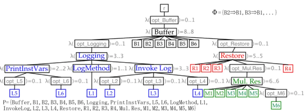
The result from applying this algorithm to the change specification of Figure 2 is presented in Figure 6. It is more complex but semantically equivalent to the FD of Fig-ure 5. Actually, the algorithm makes abundant use of dummy featFig-ures, not only for the
LogMethod Restore !( )=5..5 !( )=8..8 !( )=3..3 Mul. Res !( )=0..1 Buffer Logging PrintInstVars B2 B1 B3 B4 B5 B6 R1 R2 R3 R4 M4 M6 M1 M2M3 M5 L1 opt_Buffer opt_Logging !( )=0..1opt_Restore opt_Mul.Res !( )=0..1opt_L5 !( )=0..1opt_L6 L6 L5 L2 L3 L4 !( )=0..1opt_M6 !( )=0..1opt_L4 Invoke Log opt_L3 !( )=0..1opt_L2 !( )=6..6 !( )=3..3 !( )=2..2 !( )=1..1 !"#$⇒#%&#'⇒#%&((()
!
*!"#+,,-.&#%&#$&#'&#/�&2344564&*.5678697:;.9&20&21&234<-7=3>&2%& 86?3@-234&2$&2'&2/&A-973.-&A%&A$&A'&A/&<+B(A-9&<%&<$&<'&</&<0&<1) r !( )=0..1 !( )=0..1 !( )=0..1Figure 6. Buffer FD resulting from the translation algorithm
root, but also to express optionality. These dummy features are, however, not primitive, and will not appear in the semantics of the resulting FD.2
The following theorem formalises an important property of this algorithm, which we intuitively referred to as the resulting FD having ‘the same meaning’ as the original change specification. More formally, the algorithm preserves the semantics of the change specification.
Theorem 12 (Correctness of algorithm 1). Let cs2fd denote the translation function described by algorithm 1. Then for each change specification Cs, f latten([[Cs]]) = [[cs2f d(Cs)]] where f latten(Set) = {a ∪ b|(a, b) ∈ Set}.
5.2. Applications
Given algorithm 1 and Theorem 12, it is possible to translate a change specification Cs into an FD d whose legal products are exactly the legal change composition/feature set pairs of the change specification. This means that we can analyse d instead of Cs but interpret the results in terms of Cs. Here we present several analysis methods for FDs and show how they can be useful in the context of ChOP.
A first application of FDs was already hinted at in the previous sections. Indeed, given a change composition/feature set pair, it is legal iff it is a product of the FD. Which means that we can use FD tools to check the validity of change composition/feature set pairs. Formally, given a change specification Cs, H ⊆ C and G ⊆ F , then
(H, G) is legal iff (H ∪ G) ∈ [[cs2f d(Cs)]].
Furthermore, we can use the FD to determine the feature compositions that are legal wrt. a change composition, i.e.
f comp(H) = {P ∩ F |P ∈ [[cs2f d(Cs)]] ∧ H = P ∩ C}, where H ⊆ C, or the other way around, with G ⊆ F
Input: A change specification Cs = (C, F, Sub, F 4C, D) Output: an FD d = (N, P, r, λ, DE, Φ)
% Initialisations r ← a new fresh node; P ← C ∪ F ; N ← P ∪ {r}; (λ, DE, Φ) ← (∅, ∅, ∅); % Mapping root features
Let roots ← {f | f ∈ F ∧ ¬∃f0· f0 ?→ f }; Let i ← 0;
foreach n ∈ roots do f ← a new fresh node; N ← N ∪ {f } ; λ ← λ ∪ {f 7→ card1[0..1]}; DE ← DE ∪ {(r, f ), (f, n)} ; i ← i + 1; end λ ← λ ∪ {r 7→ cardi[i..i]};
%Mapping non-root features & changes foreach f ∈ F do i ← 0; foreach n ∈ {f0| (f, f0, x) ∈ Sub} ∪ {c | F 4C(c) = (f, x)} do if x=man then DE ← DE ∪ {(f, n)} ; end else
Let z ← a new fresh node; N ← N ∪ {z} ; λ ← λ ∪ {z 7→ card1[0..1]}; DE ← DE ∪ {(f, z), (z, n)} ; end i ← i + 1; end λ ← λ ∪ {f 7→ cardi[i..i]}; end
% Mapping change dependencies foreach (c, c0) ∈ D do
Φ ← Φ ∪ {“c ⇒ c0”} ; end
Algorithm 1:Transforming a Cs to an FD
ccomp(G) = {P ∩ C|P ∈ [[cs2f d(Cs)]] ∧ G = P ∩ F }.
If f comp(H) or ccomp(G) return an empty set, we know that H is an illegal change composition, respectively C an illegal feature set. Otherwise, the results of f comp(H) (resp. ccomp(G)) can easily be used to determine the minimal/maximal feature set (resp. change composition), it suffices to take the element of f comp(H) (resp. ccomp(G)) with minimal/maximal cardinality.
A common analysis means for FDs are metrics defined on the FD [21]. For instance, as FDs are generally used to express the variability of a software product line, the number of products of an FD |[[d]]| is a measure its variability of the software product line. If the FD was obtained from a change specification, it measures the variability of the change specification. This kind of metric is already implemented in FD tools such as FAMA [21].
Obtaining the same information based on only the data in Figure 2 would require a new algorithm and would consequently imply more work.
A similar metric would be to determine in how many ways a feature set G ⊆ F can be implemented, and how many changes are needed (at most/least) to implement it. This can be done by calculating f comp(H) and determining the minimal/maximal cardinality of its elements. A configuration tool, i.e. a tool that lets a user choose which features to include, could then show this kind of statistics while performing the choices.
If additional information about changes is available, such as the lines of code added or additional memory consumption, it can be added to the FD in the form of feature attributes. The configuration tool could then show more comprehensive statistics about the user’s current feature selection. Instead of seeing merely how many changes it will require, the user will be able to see to what extend the resulting application will grow in code size or memory consumption. Instead of showing metrics to the user, the configu-ration tool could also choose the change composition itself, for instance by selecting the one that is optimal wrt. an objective function (e.g. minimise memory consumption) [21]. The advantage here is that the attribute values would be automatically derived from the actual changes in the code without the need for human intervention.
Another application of FDs is to determine which features are always present (called commonality), comm(d) = T[[d]], and which are never present (called dead features), dead(d) = P \S[[d]]. If we project these results to the sets of changes comm(cs2f d(Cs)) ∩ C and dead(cs2f d(Cs)) ∩ C, we obtain the set of changes which are always/never present in the system. With the current model of ChOP, however, these indicators are not very useful. As shown in the proof of Theorem 7, the change composition/feature set consisting of all changes and features is always legal, hence dead(cs2f d(Cs)) = ∅. Furthermore, through algorithm 1, each top-level feature of the change composition becomes optional, hence comm(cs2f d(Cs)) = ∅.
A more subtle and relevant approach would be to consider the number of occur-rences of a change or feature among the set of legal compositions. A change with a high frequency (‘almost common’, one could say) could suggest a refactoring to make the cor-responding code efficient, whereas no effort should be put in code that is ‘almost dead’. Formally, a tool should indicate, given a change c ∈ C, whether
|{p | p ∈ [[cs2f d(Cs)]] ∧ c ∈ p}|
|[[cs2f d(Cs)]]| > k1 (resp. < k2) where k1and k2are some fixed thresholds.
6. Conclusion and future work
ChOP, in which features are seen as sets of changes that can be applied to a base program, has recently been proposed as an approach to feature-oriented programming. In ChOP, changes are recorded as the programmer works and can encapsulate any developer action, including the removing of code. Before changes can be combined to form a product, it has to be made sure that they are free of harmful interactions. There exists, however, no formal model of the current approach that would allow to define properties such as this independently from an actual implementation.
In this paper, we make an effort to fill this gap with two contributions. First we pro-pose a formal model of change-oriented programming, define properties such as com-posability, and then show that ChEOPS, the proof-of-concept implementation of ChOP, adheres to this model. Second, we map the model to the well-understood notion of FDs, which has become one of the standard modelling languages for variability in SPLE. The mapping, provided in form of a translation algorithm, allows us to reuse a number of results in FD research and apply them to ChOP.
The elaboration of the formal ChOP model lead us to take a high-level look at ChOP, independent from an implementation, which allowed us to identify new interesting prop-erties and to make some generalisations. Therefore, an immediate topic for future work is to improve ChEOPS based on the feedback gathered while developing the formal model. For instance, the current version is not expressive enough to cover the whole formal model, given that the relations between a feature and its changes (F 4C) and between features (Sub) are implemented with the restriction that the optionality of a sub-feature (change) wrt. its parent is an attribute of the parent, and not of the relation. The design and implementation of ChEOPS will be refactored to overcome this issue.
Another example of future work induced by the formal model are the different strate-gies that can be used to produce legal change compositions. At the time of writing, we only formalised two of them: produce maximal (respective minimal) legal change com-positions. Retrospectively, we realised that given a set of features, ChEOPS currently always produces a maximal change composition. This strategy makes sense, since it pro-duces the system with the most complete implementation of the corresponding feature set. Other strategies are currently being considered for implementation. Namely, allow-ing the user to create the minimal change composition for a set of features might be in-teresting in the case where code size needs to be minimised, as it returns the most basic implementation of a feature set. Yet another strategy could be a mix of both in which the optional changes that add code are included and the optional changes that remove code are omitted. These strategies will be formalised and then implemented in ChEOPS.
Currently, the dependencies between change objects reflect low-level constraints only. The new connection between FDs and ChOP also allows to express dependencies and constraints on the application level. Another track of future work may consist in how to carry back such dependencies and constraints to the change object level.
A final track of future work consists in extending the range of applications of FDs to ChOP. In this paper, we only used FDs to validate change compositions and to express basic properties of change specifications. The state-of-the-art work on FDs, however, in-cludes many more applications such as visual modelling support, specification of met-rics, program understanding, etc. which we plan to investigate in order to find out how they can be helpful in ChOP.
Acknowledgements
We thank the anonymous referees for their helpful comments. This work is sponsored by the Interuniversity Attraction Poles Programme of the Belgian State of Belgian Science Policy under the MoVES project and the FNRS.
References
[1] Pohl, K., Bockle, G., van der Linden, F.: Software Product Line Engineering: Foundations, Principles and Techniques. Springer (July 2005)
[2] Svahnberg, M., van Gurp, J., Bosch, J.: A taxonomy of variability realization techniques. Software – Practice and Experience 35(8) (2005) 705–754
[3] Nakkrasae, S., Sophatsathit, P.: A formal approach for specification and classification of software com-ponents. In: SEKE ’02: Proceedings of the 14th international conference on Software engineering and knowledge engineering, New York, NY, USA, ACM (2002) 773–780
[4] Ed Jung, Chetan Kapoor, D.B.: Automatic code generation for actuator interfacing from a declara-tive specification. In: International Conference on Intelligent Robots and Systems. (IROS 2005). 2005 IEEE/RSJ. (2005) 2839 – 2844
[5] Apel, S., Lengauer, C., Batory, D., M¨oller, B., K¨astner, C.: An algebra for feature-oriented software development. In: Proceedings of the International Conference on Algebraic Methodology and Software Technology (AMAST). Springer-Verlag (2007)
[6] Batory, D., Sarvela, J.N., Rauschmayer, A.: Scaling step-wise refinement. Transactions on Software Engineering 30(6) (2004) 355–371
[7] Batory, D.S.: A tutorial on feature oriented programming and the ahead tool suite. In: GTTSE. (2006) 3–35
[8] Ebraert, P., Van Paesschen, E., D’Hondt, T.: Change-oriented round-trip engineering. Technical report, Vrije Universiteit Brussel (2007)
[9] Ebraert, P., Vallejos, J., Costanza, P., Van Paesschen, E., D’Hondt, T.: Change-oriented software engi-neering. In: ICDL ’07: Proceedings of the 2007 international conference on Dynamic languages, New York, NY, USA, ACM (2007) 3–24
[10] Kang, K., Cohen, S., Hess, J., Novak, W., Peterson, S.: Feature-Oriented Domain Analysis (FODA) Feasibility Study. Technical Report CMU/SEI-90-TR-21, SEI, Carnegie Mellon University (November 1990)
[11] Batory, D.S.: Feature Models, Grammars, and Propositional Formulas. In: Proceedings of the 9th Int. Software Product Line Conference (SPLC). (2005) 7–20
[12] Bontemps, Y., Schobbens, P.Y., Heymans, P.: Generic semantics of feature diagram variants. In: Feature Interactions in Telecommunications and Software Systems VIII. (ICFI’05). (September 2005) 58–77 [13] Schobbens, P.Y., Heymans, P., Trigaux, J.C., Bontemps, Y.: Generic semantics of feature diagrams.
Computer Networks (2006), special issue on feature interactions in emerging application domains (2006) 38
[14] Parnas, D.L.: On the criteria to be used in decomposing systems into modules. Comm. ACM 15(12) (1972) 1053–1058
[15] Batory, D., O’Malley, S.: The design and implementation of hierarchical software systems with reusable components. ACM Trans. Softw. Eng. Methodol. 1(4) (1992) 355–398
[16] Xing, Z., Stroulia, E.: Umldiff: An algorithm for object-oriented design differencing. In: Proceedings of the 20th International Conference on Automated Software Engineering. (2005)
[17] Robbes, R., Lanza, M.: A change-based approach to software evolution. Electronic Notes in Theoretical Computer Science (2007) 93–109
[18] Ducasse, S., Demeyer, S.: The FAMOOS Object-Oriented Reengineering Handbook. University of Bern (1999)
[19] Tichelaar, S.: Modeling Object-Oriented Software for Reverse Engineering and Refactoring. PhD thesis, University of Bern (2001)
[20] Czarnecki, K., Eisenecker, U.W.: Generative Programming: Methods, Tools, and Applications. Addison-Wesley, Boston (2000)
[21] Benavides, D., Ruiz-Cort´es, A., Trinidad, P.: Automated Reasoning on Feature Models. Proceedings of the 17th International Conference (CAiSE’05) LNCS, Advanced Information Systems Engineering. 3520 (2005) 491–503
[22] Metzger, A., Heymans, P., Pohl, K., Schobbens, P.Y., Saval, G.: Disambiguating the documentation of variability in software product lines: A separation of concerns, formalization and automated analysis. In: Proceedings of the 15th IEEE International Requirements Engineering Conference (RE’07), New Delhi, India (October 2007) 243–253
[23] E´en, N., S¨orensson, N.: An extensible sat-solver. Theory and Applications of Satisfiability Testing (2004) 502–518