RESEARCH OUTPUTS / RÉSULTATS DE RECHERCHE
Author(s) - Auteur(s) :
Publication date - Date de publication :
Permanent link - Permalien :
Rights / License - Licence de droit d’auteur :
Bibliothèque Universitaire Moretus Plantin
Institutional Repository - Research Portal
Dépôt Institutionnel - Portail de la Recherche
researchportal.unamur.be
University of Namur
Quantum vacuum photon modes and repulsive Lifshitz-van der Waals interactions
Dellieu, Louis; Deparis, Olivier; Muller, Jérôme; Kolaric, Branko; Sarrazin, Michaël
Published in:
Physical Review B - Condensed Matter and Materials Physics
DOI:
10.1103/PhysRevB.92.235418 Publication date:
2015
Document Version
Peer reviewed version
Link to publication
Citation for pulished version (HARVARD):
Dellieu, L, Deparis, O, Muller, J, Kolaric, B & Sarrazin, M 2015, 'Quantum vacuum photon modes and repulsive Lifshitz-van der Waals interactions', Physical Review B - Condensed Matter and Materials Physics, vol. 92, no. 23, 235418. https://doi.org/10.1103/PhysRevB.92.235418
General rights
Copyright and moral rights for the publications made accessible in the public portal are retained by the authors and/or other copyright owners and it is a condition of accessing publications that users recognise and abide by the legal requirements associated with these rights. • Users may download and print one copy of any publication from the public portal for the purpose of private study or research. • You may not further distribute the material or use it for any profit-making activity or commercial gain
• You may freely distribute the URL identifying the publication in the public portal ?
Take down policy
If you believe that this document breaches copyright please contact us providing details, and we will remove access to the work immediately and investigate your claim.
Louis Dellieu1,∗ Olivier Deparis, J´erˆome Muller, Branko Kolaric, and Micha¨el Sarrazin1† Research Center in Physics of Matter and Radiation (PMR), Department of Physics,
University of Namur, 61 rue de Bruxelles, B-5000 Namur, Belgium
The bridge between quantum vacuum photon modes and properties of patterned surfaces is cur-rently being established on solid theoretical grounds. Based on these foundations, the manipulation of quantum vacuum photon modes in a nanostructured cavity is theoretically shown to be able to turn the Lifshitz-van der Waals forces from attractive to repulsive regime. Since this concept relies on surface nanopatterning instead of chemical composition changes, it drastically relaxes the usual conditions for achieving repulsive Lifshitz-van der Waals forces. As a case study, the potential in-teraction energy between a nanopatterned polyethylene slab and a flat polyethylene slab with water as intervening medium is calculated. Extremely small corrugations heights (less than ten nanome-ters) are shown to be able to turn the Lifshitz-van der Waals force from attractive to repulsive, the interaction strength being controlled by the corrugation height. This new approach could lead to various applications in surface science.
1
These authors have contributed equally to this work.
I. INTRODUCTION
Many fundamental aspects and practical issues in the physics of interfaces are related to controlling interac-tions between surfaces [1, 2]. In his seminal article [3], De Gennes pointed out the importance of van der Waals and electrostatic forces in adsorption, adhesion and wet-ting phenomena. Recently, it became obvious that con-trolling forces between macroscopic bodies or surfaces is crucial for a variety of applications such as mechanics of nanomachines, stability of colloids and communication between biological cells, for instance [1, 2, 4, 5].
The growing interest for nanoelectromechanical sys-tems (NEMS) urges the scientific community to deeply study van der Waals and electrostatic interactions within nanostructured systems [6, 7]. In particular, looking at nanostructures in the theoretical framework of dispersive (van der Waals) interactions turns out to be of great in-terest, from both fundamental perspectives and quantum based-technologies [8]. In order to understand the influ-ence of surface corrugations on Lifshitz-van der Waals in-teractions between macroscopic bodies, many approaches have emerged, each one addressing specific corrugation geometries [7]. On one hand, additive methods, such as the proximity force approximation (PFA) or the pairwise summation (PWS), appear to be the most employed ones while describing interactions between smooth corrugated surfaces at short and long separation distances, respec-tively [7, 9]. On the other hand, while considering corru-gated surfaces with small correlation length (of the order of the separation distance), nonadditive methods such as the scattering or perturbative approaches are required in order to take into account diffraction and correlation ef-fects which occur at the nanoscale [7, 10]. However, it is noteworthy that refinements of the above mentioned
∗Electronic address: [email protected] †Electronic address: [email protected]
approaches have led to their progressive convergence for specific corrugations size and shape [7].
This article focuses on small correlation length nanos-tructures with steep features. In this case, the assim-ilation of the surface corrugation to a graded effective refractive index layer is relevant [11–13] and allows sim-plifying greatly the application of nonadditive methods, while still taking fully into account electrodynamical cou-pling between features as it will be explained below. Mo-tivated by recent theoretical [13–15] and experimental [16] studies, we introduce the novel concept of manipu-lating quantum vacuum photon modes at the sub-10nm scale in order to turn Lifshitz-van der Waals interactions from attractive to repulsive.
The article is organized as follows. After introduc-tion (Secintroduc-tion I), we present in Secintroduc-tion II the theoretical framework used for the description of the Lifshitz-van der Waals interactions and we explain our theoretical ap-proach for calculating the interfacial energy in the case of steep nanocorrugated surfaces. The relevant approxi-mation used to describe steep nanocorrugated surfaces is introduced and justified in the Section III. In Section IV we report on computational results and discuss how sub-10 nm corrugations allows us to control quantum vacuum photon modes and, by this way, to turn the Lifshitz-van der Waals force from attractive to repulsive. Perspectives and general remarks are finally provided in Section V.
II. THEORETICAL APPROACH
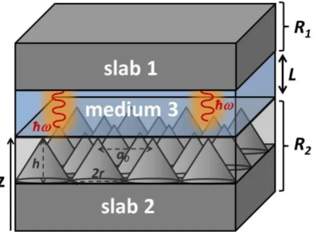
Over the last decades, the Lifshitz - van der Waals ap-proach of interfacial interactions in macroscopic systems has been widely investigated, both theoretically and ex-perimentally [17–23]. Although usually attractive, the interaction potential energy may become repulsive if par-ticular conditions are satisfied [24]. Let us first consider a body (1) interacting with a body (2) via an interven-ing medium (3) (Fig. 1). Let us also consider for the moment that each element of this macroscopic system
2 has a planar geometry (for now body (2) is treated as
a flat homogeneous slab) and is characterized by a di-electric function ε(iξ), where iξ is the imaginary angular frequency. It is well established that repulsive Lifshitz-van der Waals interactions between the two bodies can take place if the following condition is satisfied [24]:
ε1(iξ) < ε3(iξ) < ε2(iξ) (1)
where εi is the dielectric function of the ith component
of the system. Eq. (1) cannot be satisfied if the inter-vening medium is vacuum. Therefore, a liquid or a gas is needed to satisfy Eq. (1) for given slab materials [24]. Moreover, in practice, Eq. (1) imposes tight constraints on the choice of both the materials and the intervening medium, which makes challenging the experimental ob-servation of repulsive Lifshitz-van der Waals interactions [25, 26].
Hereafter, we introduce an original approach to mod-ify Lifshitz-van der Waals interactions in a very differ-ent perspective, beyond the constraint set by Eq. (1). By tuning the virtual photon exchange between the two bodies, via nanopatterning of the surface of one of them (Fig. 1), it is possible to obtain a repulsive interaction potential energy, without any modification of the chem-istry of materials, i.e. without changing their dielectric functions. The nature of the Lifshitz-van der Waals force – repulsive or attractive – is solely the result of control-ling light-matter quantum interactions at the nanoscale. The concept briefly described above is based on the fundamental interplay between physics of confined media and optical cavities. Here, the concept of confined space is applied to the particular geometry of a planar-like cav-ity [27–29] (Fig. 1). Actually, the present approach re-lies on joined effects of electromagnetic confinement and surface patterning at the nanoscale which are exploited to modify the interaction potential energy. In addition, since the studied system can be regarded as an optical
FIG. 1: (Color online). Bodies 1 and 2 interacting via an intervening medium 3. The two bodies are separated by a distance L. R1 (R2) is the Fresnel reflection coefficient of slab 1 (slab 2). The surface of body 2 is nanopatterned with cor-rugations that are described by a graded effective medium.
cavity, it is possible to establish a formal link between optical properties of the cavity (quality factor Q for in-stance) and Lifshitz-van der Waals forces between the slabs forming that cavity.
At the macroscopic level, the force, thus the inter-action potential energy, between two planar surfaces is related to the lowest (zero-point) energy state of the electromagnetic (EM) field, arising from the existence of virtual photons of energy 1
2~ω at all available
fre-quencies which are exchanged between both surfaces [7]. The interaction potential energy U can be written as [30] U (L) = 1
2
P
k~(ωk(L) − ωk(L → ∞)), where ωk is
the angular frequency of the kth vacuum photon-mode
available between the two surfaces separated by a length
L (Fig. 1). U (L) can be then easily related to the
density of EM states ρ(ω, L) of the system such that:
U (L) = 1
2~R ω(ρ(ω, L) − ρ(ω, L → ∞))dω. The quantity
ρ(ω, L) can be obtained from classical electrodynamics.
The tuning of the zero-point energy is possible thanks to the presence of surfaces (boundaries), i.e., the pres-ence of allowed modes of the EM field within the cav-ity [5, 7]. Taking this fact into account, the force ap-pears at the macroscopic level as the result of a mani-fold of vacuum photon modes occurring because the EM field must meet the appropriate boundary conditions at each surface. Moreover, these vacuum photon modes can be altered by patterning the surfaces [27], i.e. EM field boundaries.
As explained above, the interaction potential energy considered in the present case results from the exchange of virtual photons between two interacting bodies. By summing the individual energies related to each mode available within the cavity, we can retrieve the total en-ergy of the system from the photon density of states. Based on these arguments, we apply the so-called scat-tering approach [7] to calculate the interaction potential energy between two bodies facing each other. Accord-ingly, the interaction potential energy U is given by:
U (L) = ~ 2π X m=s,p Z d2k // (2π)2 Z ∞ 0 dξ (2) × ln(1 − Rm1(iξ, k//)Rm2 (iξ, k//)e−2κL)
where L is the separation distance between the bodies,
κ =qξc22 + |k//|2 , R
m
1(R2m) is the generalized complex
reflection coefficient of the first body (second) in the m polarization state (s or p states), k// is the parallel
com-ponent of the photon wave vector and iξ is the imagi-nary angular frequency [31]. It is noteworthy that, in this method, the nanopatterned slab (here body (2)) is treated as a graded effective medium (see [13] and dis-cussion below).
For short separation distances (L ≤ 10 nm), Eq. (2) is well approximated by the so-called Hamaker formula [32]:
where A132 is the effective Hamaker constant of the
sys-tem which can be deduced from the numerically com-puted energy, i.e., Eq. (2).
In case the intervening medium is vacuum, Eq. (2) ap-pears to be efficient since it reproduces well experimental results [13]. In this case, using Eqs. (2) and (3), it is pos-sible to retrieve the Hamaker constant A12of the system
(A12 ≡ A132, where (3) is omitted when the intervening
medium is vacuum). Using the same procedure, it is also possible to retrieve the Hamaker constant A11of the flat
surface. The effective Hamaker constant A22 of the
pat-terned surface, on the other hand, can be deduced indi-rectly from the well-known relation [2] A12=√A11√A22
by using values of A12 and A11 calculated from Eqs. (2)
and (3).
For numerical convenience [33, 34], instead of comput-ing directly A132 via Eq. (2) to obtain the interaction
potential energy, we compute the effective Hamaker con-stant of the system (hereafter, (3) stands for fluid) from the well-known relation [2, 33, 34]:
A132= (pA11−pA33)(pA22−pA33) (4)
where Aii are the Hamaker constants of the
correspond-ing media which are obtained from the above described procedure. Repulsive interaction potential energy is reached when A132 is negative, cf. Eq. (3). Therefore,
according to Eq. (4), such a condition is fulfilled when :
A22< A33< A11. (5)
The condition imposed by Eq. (5) goes beyond the constraint set by Eq. (1). Indeed, when considering a nanopatterned surface, as in the present case, Eq. (1) can not be used since dielectric functions are those of flat materials. On the other hand, Eq. (5) allows to by-pass this problem since the effective Hamaker constant of the nanopatterned surface can be calculated by the above described procedure. Therefore, Eq. (5) has a more gen-eral application since it can be used simultaneously for both flat and nanopatterned surfaces.
III. MODELLING AND SIMULATION DETAILS
Let us now develop the case of a practical two-body system consisting of two polyethylene (PE) slabs facing each other and separated by a L distance. In order to ful-fill Eq. (5), we choose water (medium 3) as intervening medium. It must be pointed out that such a configu-ration does not match Eq. (1). The first slab (slab 1) has a flat (planar) surface while the second one (slab 2) is nanostructured with cones of height h arranged on a hexagonal lattice with a lattice period chosen to be a0=
10 nm (Fig. 1). We choose a fixed cone base radius of
r = 5 nm and a variable cone height h (ranging from 10
to 100 nm) in order to alter the optical properties of the
FIG. 2: (Color online). Hamaker constant A22 of nanopat-terned polyethylene slab (see inset) as a function of cones height h.
surface. Indeed, such a geometry is known to improve the antireflection behavior of the surface which in turns alters the vacuum photon modes of the system [13, 35]. Moreover, since the PE surface is hydrophobic [1], we can assume a Cassie state [36] between water and the corru-gated PE surface [13]. As a consequence, the void space between cones is filled by air and water is localized above the top of the cones only.
At wavelengths below 20 nm, PE permittivity is close to unity [37] and thus only vacuum modes above this spectral range are relevant. Since the lattice period is shorter than the relevant wavelength range, the patterned surface can be described by an effective material, i.e. an effective medium approach (EMA), with a graded per-mittivity εef f(z) along its thickness such that:
εef f(z) = 1 + (εP E− 1)f(z) (6)
where εP Eis the PE dielectric function, f (z) is the filling
fraction given by f (z) = πr(z)2/S with S = a2 0
√
3/2 and
r(z) the radius of the circular section of the cones at
coordinate z.
The use of the EMA has to be justified with great care. Indeed, such an approximation usually requires the sep-aration distance L to be equal or larger than the lattice parameter a0 of the periodically nanostructured surface
[14]. The reason is that the distance is one of the main parameter determining the nature of the electromagnetic modes (radiative or evanescent) involved in the calcu-lation of the Lifshitz-van der Waals interaction. In the case of a separation distance shorter than the lattice pa-rameter, evanescent modes are dominant and are able to reproduce the details of the nanostructure, thereby inval-idating the EMA [38, 39]. However, in the present situa-tion, the EMA remains valid for the separation distances shorter than the lattice parameter. This non-intuitive re-sult emerges from the weakness of the coupling between diffracted and specular orders due to both the optical
4
FIG. 3: (Color online). Hamaker constant A132 of flat polyethylene/patterned polyethylene system immersed in wa-ter (schematic view in the inset) as a function of cones height h.
properties of PE and the steepness of the corrugation (see Appendix A for a detailed justification of the use of EMA).
The impact of the choice of water as the intervening medium has to be examined. Indeed, as a polar liquid, water induces an electrostatic double layer at both sur-faces facing each other, giving rise to an additional elec-trostatic repulsive force between them which, in exper-iments, could screen the Lifshitz-van der Waals repul-sive force treated here. However, while considering the Cassie state regime, the electrostatic double layer is lo-cated only on the top of the cones which become steeper while increasing the cones height. As a consequence, the electrostatic double layer associated to the steep nanocor-rugated PE surface becomes extremely small, leading to a dramatic decrease of the electrostatic repulsive inter-action (see Appendix B). Therefore, in the present sit-uation, the electrostatic repulsive interaction can be ne-glected compared to the Lifshitz-van der Waals interac-tion for any corrugainterac-tions height.
The corner stone of the present approach is related to the fact that tuning antireflective properties of the bot-tom slab (thanks to nanocorrugations) allows tailoring the virtual photon exchange within the cavity formed by the top flat PE slab and the bottom corrugated PE slab [13]. Since the presence of virtual photons causes dis-persive interaction energy between slabs, it enables the control of the magnitude of attraction/repulsion between the two surfaces by only playing on the photon mode den-sity inside the cavity.
IV. RESULTS AND DISCUSSION
As explained previously, the use of a fluid as inter-vening medium led no choice but to compute individual Hamaker constants of each component of the system in
FIG. 4: (Color online). Interaction potential energy between PE slabs as a function of cones height.
a first step. We calculate from previously reported data [13] the effective Hamaker constant A22of the corrugated
PE slab using Eq. (2) and Eq. (3) for various cones height (Fig. 2). Knowing the Hamaker constant A11 of
flat PE surface (A11 = 0.36 eV) [40] and the Hamaker
constant A33 of water (A33 = 0.23 eV) [2], we then
cal-culated the Hamaker constant A132 of the whole system
from Eq. (4), as a function of the cones height (Fig. 3). Strong decrease of the Hamaker constant A132 with
in-creasing cones height is observed, going from positive to negative values (Fig. 3). Here, the zero-crossing point for A132 takes place for h0 ≈ 3 nm. This critical point
is reached when A22 = A33 (horizontal red-dotted line,
Fig. 2), in accordance with the fact that repulsive in-teraction is achieved only if Eq. (5) is satisfied. There-fore, the interaction potential energy becomes positive,
i.e. repulsive force (Fig. 4), for h > h0 as soon as the
Hamaker constant A132 of the system becomes negative
(see footnote [41]). It is noteworthy that, due to the small zero-crossing point value h0, it could be experimentally
difficult to achieve a progressive transition from attrac-tive to repulsive force while increasing the cones height (see footnote [42], [43]). Thus, observation of this pro-gressive transition would require higher h0 value which
could be achieved by using flat materials with Hamaker constants A22(h =0) higher than the Hamaker constant
A33 of the intervening medium (by at least one order
of magnitude, see Fig. 2). Furthermore, owning to the Cassie state regime of the present model, such materials are difficult to find [1]. Consequently, the transition from attractive to repulsive regimes cannot be easily observed as well as significantly modified (i.e. h0 value stays in
the same range for most of the materials).
Such a dramatic modification of the dispersive en-ergy of the system arises from the strong decrease of the Hamaker constant A22 of the nanopatterned PE slab as
the cone height increases (note the logarithmic scale in Fig. 2). Phenomenologically, this result can be explained
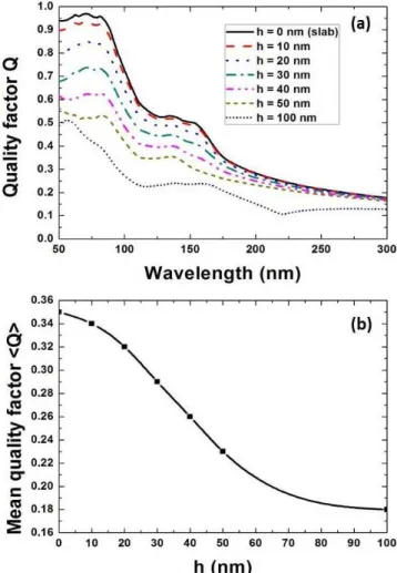
FIG. 5: (Color online). (a) Quality factor Q of the Fabry-Perot cavity formed by the flat polyethylene slab and the patterned polyethylene slab. Q is given against the wave-length for various cone heigths. (b) Mean value (integration over wavelength) of the quality factor of the cavity described above. Both slabs are separated by water.
by the fact that the increase of the cone height h causes the decrease of the reflection coefficient of the nanopat-terned PE slab R2. Consequently, the quality factor Q
of the Fabry-Perot cavity also decreases (Fig. 5a) since [44]:
Q = −2π 1
ln(R1R2(1 − A3)2)
2L
λ (7)
where Ri= |Ri|2and A3is the optical absorption loss of
the intervening medium (3) for a single path in the cavity (i.e. A3 is given by Beer-Lambert law). Moreover, the
mean value of the quality factor < Q > was calculated by integration of Eq. (7) in the relevant spectral range from 50 nm to 300 nm (Fig. 5b). We observe a decrease of < Q > as the cones height increases, down to 49 % of the initial value (i.e. for flat slabs) (Fig. 5b). As Q de-creases, the EM energy stored into the Fabry-Perot cavity is reduced [44]; i.e., the number of vacuum photon modes
available within the cavity and which contribute to the interaction potential energy U (L) ∝ P
k~ωk(L)
dimin-ishes. Therefore, the attractive behavior of the interac-tion potential energy becomes weaker while, owing to the geometry of the studied system and the choice of materi-als, the repulsive behavior becomes stronger. On overall, controlling the optical properties of the cavity enables tuning the strength of the attractive/repulsive force. It is noteworthy that such an interpretation, although based on solid physical ground (i.e. the energy storage in an optical cavity), relies on a heuristic approach and still requires the establishment of a direct theoretical link be-tween the quality factor and the Lifshitz-van der Waals interaction.
V. CONCLUSION
In conclusion, we showed theoretically that extremely small and steep nanoscopic corrugations on the surface of one of the two interacting bodies are able to turn Lifshitz-van der Waals interaction from attractive to repulsive, as well as to control the strength of their interaction by changing the corrugations height. The present approach is appealing since it offers the possibility to achieve repul-sive interaction only by nanopatterning one of the sur-faces. Therefore, constraints with respect to the choice of materials [24–26] are relaxed. In the end, we are aware of the fact that an experimental proof of the concept is a very difficult task due to engineering complexity re-lated to the achievement of the pattern depth of just a few nanometers. However, in the light of a recent experi-mental study [16], the presented concept could open new perspectives to control attractive/repulsive interactions by nanopatterning. Indeed, fabricated patterns could be used to control macroscopic interactions in a variety of applications ranging from biology [45] to material science for controlling wettability, adhesion and adsorption [1, 2].
Acknowledgments
L.D. is supported by the Belgian Fund for Indus-trial and Agricultural Research (FRIA). M.S. is sup-ported by the Cleanoptic project (development of super-hydrophobic anti-reflective coatings for solar glass pan-els/convention No.1117317) of the Greenomat program of the Wallonia Region (Belgium). B. K. acknowledges financial support from the Action de Recherche Con-cert´ee (BIOSTRUCT project) of the University of Namur (UNamur) and the support from the Nanoscale Quan-tum Optics COST-MP1403 action. This research used resources of the “Plateforme Technologique de Calcul In-tensif” (PTCI) (http://www.ptci.unamur.be) located at the University of Namur, Belgium, which is supported by the F.R.S.-FNRS. The PTCI is member of the “Con-sortium des Equipements de Calcul Intensif (CECI)” (http://www.ceci-hpc.be).
6
APPENDIX A: JUSTIFICATION OF THE EFFECTIVE MEDIUM APPROACH
Although the effective medium approach (EMA) is fully relevant in optics while dealing with the far field, it could be objected that it is inappropriate to describe the near field, which plays a non trivial role in the cal-culation of the interaction potential energy at the short distances[46, 47]. Indeed, the evanescent near field ex-hibits lateral fluctuations which are expected to mimic the surface corrugation [48]. Therefore, EMA is a
pri-ori inappropriate in describing accurately these fluctu-ations. However, the careful analysis described below leads to qualify this restriction in the specific case of sub-wavelength periodically patterned surfaces. The specular order couples with all the evanescent diffracted orders, which are all coupled together as well. As a result, they constitute the fluctuating near field. Let us formally ex-amine such couplings in the theoretical framework of the Rigorous Coupled Wave Analysis (RCWA) method [49]. The Fourier series expansion of the dielectric constant writes as :
ε(z, ρ) =X
g
εg(z)eig.ρ (A1)
where ρ denotes a real-space vector in the primitive cell with basis vectors a1and a2(Fig. 6), and g is a
recipro-cal lattice vector. By virtue of Floquet-Bloch theorem, the electric E and displacement D fields expand as :
E(z, ρ) =X
g
Eg(z)ei(g+k//).ρ (A2)
D(z, ρ) =X
g
Dg(z)ei(g+k//).ρ (A3)
Since D = ε0ε(z, ρ)E, we can re-write Dg(z) as : Dg(z) =
X
g′
ε0εg,g′Eg′(z) (A4)
FIG. 6: (Color online). Primitive cell of the periodic pat-terned structure under study. In computations, the cone is described by a stack of cylinder of radius a ∈ [0,r].
where g′ is another reciprocal lattice vector and the
Fourier matrix element εg,g′ expresses the coupling
be-tween diffracting orders g and g′. When describing the
cones by cylinders stack, εg,g′ in a given layer is written
as : εg,g′ = εmδg,g′+ (εs− εm) 2πa2 σ J1(| g − g′| a) | g − g′| a (A5)
where a is the cylinder radius at coordinate z (Fig. 6),
J1 is the first-order Bessel function, εm is the dielectric
constant of surrounding medium (here, vacuum), εs is
the dielectric constant of PE, δg,g′ is the Kronecker
sym-bol and σ is the primitive cell surface (Fig. 6). Due to the subwavelength size of the corrugation period, mode coupling (Eq. A5) gives rise to evanescent waves propa-gating along the surface.
Careful examination of Eq. A5 indicates that the coupling constant εg,g′ vanishes in two limit cases: (1)
for low refractive index contrast, i.e. εs → εm, (2)
in the topmost layers where the cylinder radius a be-comes very small and ultimately tends to zero (note that lima→0J1(|g−g
′|a)
|g−g′|a =
1
2). As a consequence, in both limit
cases, due to the extremely weak coupling, evanescent waves tend to vanish within the cavity. In the present study, the limit case 1 is always reached at wavelengths equal or shorter than 30 nm because of the dielectric properties of PE, i.e. ℜ(εs) → 1 and ℑ(εs) → 0 (Fig.
7). On the other hand, since evanescent waves propa-gate near the very top of the cones and given the cones steepness thereof (i.e. a → 0) the limit case 2 is always satisfied. These predictions need however to be verified by numerical simulations.
In order to probe the evanescent waves inside the cav-ity, we numerically simulated, by finite difference time domain (FDTD) [50, 51] home-made code, the diffracted field patterns which originate from oscillating dipoles in-serted inside the cavity. Such a model modelizes the elec-tromagnetic field coming from quantum fluctuations
in-FIG. 7: (Color online). Dielectric function εs of PE. Pointed
FIG. 8: (Color online). Sketches of the configuration used in FDTD simulations for the cone array structure (a) and its corresponding EMA description (b). The red arrow denotes an oscillating dipole and dashed lines delimit the limits of the computational cell. One dipole is inserted in each cells and periodically repeated.
FIG. 9: (Color online). Maps of the normalized intensity of diffracted field for different wavelengths in the three di-mensional structure (left charts in each panel) and its EMA description (right charts in each panel).
side the cavity. Both the actual 3D structure (Fig. 8a) and its corresponding EMA description (Fig. 8b) were simulated using cones height of 40 nm and a separation distance of 5 nm, as an illustration. The electromagnetic responses of both configurations to dipole excitation were probed through normalized field intensity maps (Fig. 9). Maps are drawn for each computational cell (dashed lines on Fig. 8) and display only the diffracted field i.e. dipole radiation removed. The wavelengths of the radiating
dipole (30 nm, 80 nm, 115 nm and 155 nm) were selected in order to sample the spectral range which is relevant to PE, according to its optical properties. At all these wavelengths except 30 nm, the limit case 1 is not reached (Fig. 7) but the limit case 2 is reached near the top of the cones. In all cases, no significant differences are ob-served between the electromagnetic responses of the cone array structure and its EMA description (Fig. 9, relative error lower than 2%). This result demonstrates that the fluctuations of the evanescent waves resulting from the coupling between diffracted orders and specular order are extremely weak, which therefore plenty justifies the use of EMA in the present case.
Note that, for a cavity made of materials with mo-bile charges, surface plasmon polaritons would produce strongly modulated evanescent waves which would dom-inate Lifshitz-van der Waals interactions [47, 52]. In this case, the EMA description would obviously fail. Since PE cannot endorse surface plasmon polaritons, the above mentioned problem is excluded here.
In summary, the shallowness of evanescent waves fluc-tuations justifies the use of EMA in the present situation. The underlying physical reason is the weak modes cou-pling due to both the optical properties of PE and the steepness of the corrugation. The use of graded index profile for EMA description turns out to be reliable in rendering these shallow fluctuations. In addition, EMA avoids numerical stability issues while dealing with the direct computation of the scattering matrices of steep 3D structures made of materials with low-contrast optical in-dexes, while computing the Lifshitz-van der Waals force. This is a considerable advantage of the proposed method.
APPENDIX B: ELECTROSTATIC POTENTIAL ENERGY CALCULATION
Hereafter, we evaluate the relative contribution of elec-trostatic forces to interfacial interaction in the case of PE slabs facing each other at very small separation distance (around 10 nm). Let us first consider two flat surfaces facing each other and separated by a distance L with a liquid as intervening medium. The electrostatic potential energy associated to the electrostatic double layer formed at both surfaces is given by [1]:
W (L) = εrε0κ[2ψ1ψ2e−κL− (ψ12+ ψ22)e−2κL] (B1)
where εris the static permittivity (dielectric constant) of
the liquid, ε0 is the vacuum permittivity, κ is the inverse
of the Debye length of the liquid and ψi is the surface
potential of the ithsurface.
Replacing now one of the two surfaces by a periodi-cally nanostructured surface, here an array of cones, and using the Derjaguin approximation [1], the electrostatic potential energy is given by:
W (L) = 2πεrε0tan2(α)e−κL (B2)
8
FIG. 10: (Color online) Electrostatic potential energy be-tween PE slabs as a function of cones height. Note the orders of magnitude on the Y-axis in comparison with Fig. 4.
where α is the opening angle of the cone and S = a2 0
√ 3/2. It is noteworthy that the Derjaguin approximation is valid only if the Debye length of the liquid is smaller than the lattice period a0 of the structured surface so
that the electrostatic potential energy is not affected by coupling effects between cones.
In the case study presented in this article, the surface potential of both PE surfaces is equal to - 30mV [1], the static permittivity of water is equal to 78.2 J m−1V−2[1]
and the Debye length of water is equal to 1.5 nm [1] (the Debye length of groundwater is used for more realistic considerations). Note that the value of the Debye length allows one to use Eq. B2 since the correlation length (i.e. cones interdistance) is one order of magnitude big-ger. The electrostatic potential energy for various cones height is shown at Fig 10. The results of this calculation are commented in the article.
[1] J. Israelachvili, Intermolecular and Surface Forces (Aca-demic Press Elsevier, London, 2011).
[2] H.-J. Butt, K. Graf, and M. Kappl, Physics and Chem-istry of Interfaces (Wiley-VCH Verlag GmbH & Co. KGaA, New York, 2003).
[3] P. G. de Gennes, Rev. Mod. Phys. 57, 827 (1985). [4] A. M. Alhambra, A. Kempf, and E. Martin-Martinez,
Phys. Rev. A 89, 033835 (2014).
[5] H. B. Chan, V. A. Aksyuk, R. N. Kleiman, D. J. Bishop, and F. Capasso, Science 291, 1941 (2001).
[6] J. Yu, G. A. Rance, and A. N. Khlobystov, J. Mater. Chem. 19, 8928 (2009).
[7] M. Bordag, G. L. Klimchitskaya, U. Mohideen, and V. M. Mostepanenko, Advances in the Casimir Effect (Oxford University Press, 2009).
[8] H. J. Kimble, Nature 453, 1023 (2008).
[9] W. Broer, G. Palasantzas, J. Knoester, and V. B. Sve-tovoy, Phys. Rev. B 85, 155410 (2012).
[10] G. Palasantzas, V. B. Svetovoy, and P. J. van Zwol, Phys. Rev. B 79, 235434 (2009).
[11] A. Gusso and U. B. Reis, Europhys. Lett. 99, 36003 (2012).
[12] F. S. S. Rosa, D. A. R. Dalvit, and P. W. Milonni, Phys. Rev. A 78, 032117 (2008).
[13] L. Dellieu, O. Deparis, J. Muller, and M. Sarrazin, Phys. Rev. Lett. 114, 024501 (2015).
[14] Alexander P. McCauley, F. S. S. Rosa, Alejandro W. Ro-driguez, John D. Joannopoulos, D. A. R. Dalvit, and Steven G. Johnson Phys. Rev. A 83, 052503 (2011). [15] N. Cherroret, R. Guerout, A. Lambrecht, and S.
Rey-naud, Eur. Phys. J. D 69, 1 (2015).
[16] F. Intravaia, S. Koev, I. W. Jung, A. A. Talin, P. S. Davids, R. S. Decca, V. A. Aksyuk, D. A. R. Dalvit, and D. Lopez, Nat Commun 4, (2013).
[17] E. M. Lifshitz, Sov. Phys. JETP 2, 73 (1956).
[18] A. Lambrecht, P. A. M. Neto, and S. Reynaud, New J. Phys. 8, 243 (2006).
[19] G. L. Klimchitskaya, U. Mohideen, and V. M. Mostepa-nenko, Rev. Mod. Phys. 81, 1827 (2009).
[20] B. Geyer, G. L. Klimchitskaya, and V. M. Mostepanenko, Phys. Rev. B 81, 245421 (2010).
[21] P. J. van Zwol and G. Palasantzas, Phys. Rev. A 81, 062502 (2010).
[22] P. J. van Zwol, G. Palasantzas, and J. T. M. De Hosson, Phys. Rev. B 79, 195428 (2009).
[23] P. J. van Zwol, G. Palasantzas, and J. T. M. DeHosson, Phys. Rev. E 79, 041605 (2009).
[24] I. E. Dzyaloshinskii, E. M. Lifshitz, and L. P. Pitaevskii, Sov. Phys. Usp. 4, 153 (1961).
[25] J. N. Munday, F. Capasso, and V. A. Parsegian, Nature
457, 170 (2009).
[26] S.-W. Lee and W. M. Sigmund, Colloids and Surfaces. A, Physicochemical and Engineering Aspects 204, 43 (2002).
[27] B. Kolaric, H. Vandeparre, S. Desprez, R. A. L. Vallee, and P. Damman, Applied Physics Letters 96, 043119 (2010).
[28] M. Trupke, E. A. Hinds, S. Eriksson, E. A. Curtis, Z. Moktadir, E. Kukharenka, and M. Kraft, Applied Physics Letters 87, 211106 (2005).
[29] S. M. Dutra, Cavity Quantum Electrodynamics: The Strange Theory of Light in a Box (Wiley, Hoboken, New Jersey, 2005).
[30] D. Dalvit, P. Milonni, D. Roberts and F. da Rosa, Casimir Physics, (Lecture Notes in Physics,Springer-Verlag Berlin and Heidelberg GmbH & Co. K, 2011). [31] F. Intravaia and R. Behunin, Phys. Rev. A 86, 062517
(2012).
[32] H. C. Hamaker, Physica (Amsterdam) 4, 1058 (1937). [33] J. Visser, Advances in Colloid and Interface Science 15,
157 (1981).
[34] J. Visser, Advances in Colloid and Interface Science 3, 331 (1972).
[35] D. G. Stavenga, S. Foletti, G. Palasantzas, and K. Arikawa, Proc. Biol. Sci. 273, 661 (2006).
[36] A. B. D. Cassie and S. Baxter, Trans. Faraday Soc. 40, 546 (1944).
Hand-book of Optical Constants of Solids II edited by E. D. Palik (Academic Press Elsevier, New York, 1991). [38] R. Zhao, J. Zhou, Th. Koschny, E. N. Economou, and C.
M. Soukoulis Phys. Rev. Lett. 103, 103602 (2009). [39] Alexander P. McCauley, Rongkuo Zhao, M. T. Homer
Reid, Alejandro W. Rodriguez, Jiangfeng Zhou, F. S. S. Rosa, John D. Joannopoulos, D. A. R. Dalvit, Costas M. Soukoulis, and Steven G. Johnson Phys. Rev. B 82, 165108 (2010).
[40] C. J. Drummond and D. Y. C. Chan, Langmuir 13, 3890 (1997).
[41] The results are presented in Fig. 4 for separation dis-tances equal or shorter than the lattice parameter. Nev-ertheless, we checked that the same behavior of the inter-action potential energy (i.e. transition from attractive to repulsive regimes) was obtained for separation distances larger than the lattice parameter.
[42] Having a perfectly flat interface is not experimentally achievable [43]. However, the experimentally observed de-viations from the perfectly flat interface do not affect the concept presented here. Indeed, the Hamaker con-stant of a nanopatterned surface is modified at the global level only if the pattern exhibits short correlation lengths corrugations [13]. Because the experimentally observed
roughness occurs at long correlation length, the Hamaker constant of the ideally flat surface (in reality rough) is not affected.
[43] R. Todorov, J. Tasseva, V. Lozanova, A. Lalova, T. Iliev, and A. Paneva, Advances in Condensed Matter Physics
2013, e308258 (2013).
[44] B. E. A. Saleh and M. C. Teich, Fundamentals of Pho-tonics, 2nd ed. (Wiley-Interscience, New York, 2007). [45] Y. Liu and Q. Zhao, Biophys. Chem. 117, 39 (2005). [46] Y. Zheng and A. Narayanaswamy, Phys. Rev. A 89,
022512 (2014).
[47] F. Intravia and A. Lambrecht, Phys. Rev. Lett 94, 110404 (2005).
[48] D. Courjon, Near-Field Microscopy and Near-Field Op-tics (Imperial College Press, 2003).
[49] J.P. Vigneron, F. Forati, D. Andre, A. Castiaux, I. Derycke, and A. Dereux, Ultramicroscopy 61, 21 (1995). [50] A. Taflove and S. Hagness, Computational
Electrodynam-ics, 3rd ed., (Artech House, Boston, 2005).
[51] J. Muller, G. Parent, G. Jeandel, and D. Lacroix, Journal of the Optical Society of America A 28, 868 (2011) [52] H. Raether, in Springer Tracts in Modern Physics , edited
by G. Hohler, E.A. Nickisch (Springer, Berlin, 1988), vol. 111