HAL Id: hal-02913117
https://hal.archives-ouvertes.fr/hal-02913117
Submitted on 15 Apr 2021
HAL is a multi-disciplinary open access
archive for the deposit and dissemination of
sci-entific research documents, whether they are
pub-lished or not. The documents may come from
teaching and research institutions in France or
abroad, or from public or private research centers.
L’archive ouverte pluridisciplinaire HAL, est
destinée au dépôt et à la diffusion de documents
scientifiques de niveau recherche, publiés ou non,
émanant des établissements d’enseignement et de
recherche français ou étrangers, des laboratoires
publics ou privés.
Distributed under a Creative Commons Attribution| 4.0 International License
retro-reflector array
Erwan Mazarico, Xiaoli Sun, Jean-Marie Torre, Clément Courde, Julien
Chabé, Mourad Aimar, Hervé Mariey, Nicolas Maurice, Michael Barker,
Dandan Mao, et al.
To cite this version:
Erwan Mazarico, Xiaoli Sun, Jean-Marie Torre, Clément Courde, Julien Chabé, et al.. First two-way
laser ranging to a lunar orbiter: infrared observations from the Grasse station to LRO’s retro-reflector
array. Earth Planets and Space, Springer/Terra Scientific Publishing Company, 2020, 72 (1), pp.113.
�10.1186/s40623-020-01243-w�. �hal-02913117�
FULL PAPER
First two-way laser ranging to a lunar orbiter:
infrared observations from the Grasse station
to LRO’s retro-reflector array
Erwan Mazarico
1*, Xiaoli Sun
1, Jean‑Marie Torre
2, Clément Courde
2, Julien Chabé
2, Mourad Aimar
2,
Hervé Mariey
2, Nicolas Maurice
2, Michael K. Barker
1, Dandan Mao
1,3, Daniel R. Cremons
1, Sébastien Bouquillon
4,
Teddy Carlucci
4, Vishnu Viswanathan
1,5, Frank G. Lemoine
1, Adrien Bourgoin
6, Pierre Exertier
7,
Gregory A. Neumann
1, Maria T. Zuber
8and David E. Smith
8Abstract
We present the results of the first series of successful two‑way laser ranging experiments from a ground station, the Lunar Laser Ranging (LLR) station in Grasse, France, to a spacecraft at lunar distance, the Lunar Reconnaissance Orbiter (LRO). A 15 × 18 × 5 cm, 650‑g array of twelve 32‑mm diameter solid corner cubes is mounted on its anti‑nadir deck. Ranging to this small retro‑reflector array onboard a lunar orbiter from a ground station was a challenge compared to ranging to larger lunar surface retro‑reflectors. Grasse measured 67 returns in two 6‑min sessions on September 4, 2018. Clear returns were also recorded during two additional sessions on August 23–24, 2019 for which active slewing by LRO was performed to bring the array in view of the station. The measured echos yielded range residuals less than 3 cm (two‑way time‑of‑flight RMS < 180 ps) relative to the reconstructed LRO trajectory. This experiment provides a new method of verifying theories of dust accumulation over decades on the lunar surface. It also showed that the use of similar arrays onboard future lunar landers and orbiters can support LLR lunar science goals, particularly with land‑ ing sites near the lunar limbs and poles, which would have better sensitivity to lunar orientation.
Keywords: Laser ranging, Orbit determination, Moon, Data reduction techniques
© The Author(s) 2020. This article is licensed under a Creative Commons Attribution 4.0 International License, which permits use, sharing, adaptation, distribution and reproduction in any medium or format, as long as you give appropriate credit to the original author(s) and the source, provide a link to the Creative Commons licence, and indicate if changes were made. The images or other third party material in this article are included in the article’s Creative Commons licence, unless indicated otherwise in a credit line to the material. If material is not included in the article’s Creative Commons licence and your intended use is not permitted by statutory regulation or exceeds the permitted use, you will need to obtain permission directly from the copyright holder. To view a copy of this licence, visit http://creat iveco mmons .org/licen ses/by/4.0/.
Introduction
For 50 years, Lunar Laser Ranging to surface laser retro-reflector arrays (LRAs) by lasers at Earth stations has provided important geodetic data constraining the lunar ephemeris and orientation, with implications for both lunar interior properties and for astrophysics and funda-mental physics.
Technological improvements to the station equip-ments, such as detectors, lasers, and telescopes, have improved the accuracy of the ranging measurements from tens of centimeters to sub-cm (Murphy 2013; Courde et al. 2017b; Müller et al. 2019). Since 2008,
robotic missions from NASA and other nations have brought a wealth of new scientific data and pushed lunar science further. The recent support for commercial robotic exploration and for landed human exploration has given new opportunities for LLR. NASA Goddard Space Flight Center (GSFC) has developed a set of min-iature LRAs to be mounted on future lunar landers (Sun et al. 2019) for ranging by orbiting laser altimeters or rangefinders. Larger single retro-reflectors are being developed (Currie et al. 2011; Dell’Agnello et al. 2014) for ranging directly from Earth expanding the LLR dataset’s geometric strength.
Here, we report on a two-way laser ranging experiment at lunar distance much akin to LLR except the target is a small retro-reflector array onboard the Lunar Recon-naissance Orbiter (LRO) spacecraft, < 1/10th the area of
Open Access
*Correspondence: Erwan.Mazarico@nasa.gov
1 NASA Goddard Space Flight Center (GSFC), Greenbelt, MD, USA
the Apollo 11 array and 1/30th the mass if counting the support structure. The primary science objective is to provide baseline measurements to a new and pristine retro-reflector array at the lunar distance, as it was pro-posed that lunar dust had accumulated on the Apollo and Lunokhod retro-reflectors on the lunar surface over dec-ades and reduced their reflectivity (Murphy et al. 2010,
2014). As LLR is the only long-lived instrument on the lunar surface, understanding the potential degradation of the signal is important. Moreover, the possible system-atic effects, that would result from dust-driven thermal effects for instance, may impact the data analysis, with implications across very diverse fields from fundamental physics to geophysics.
The LRO LRA is the first on a spacecraft at lunar dis-tance to have been successfully ranged from Earth. More recently, the relay satellite Queqiao for the Chang’E 4 mission launched and included a 100-mm hollow cor-ner cube in its payload (He et al. 2018). It was placed in a halo orbit around the Earth–Moon Lagrangian point L2, ~ 450,000 km from Earth, to provide farside coverage.
In the first few years of the LRO mission, during the one-way Laser Ranging (LR) campaign (Zuber et al.
2010; Mao et al. 2017), a number of attempts were made to range to the LRO LRA from the Apache Point station (APOLLO) (Murphy et al. 2008), but these were not suc-cessful due to a number of factors, including weather, operational issues, and spacecraft geometry constraints. One major issue was the narrow range gate of the APOLLO detector (~ 100 ns) relative to the uncertainty in the spacecraft trajectory prediction, less accurate early in the LRO mission before the GRAIL gravity fields were available (Zuber et al. 2013). In 2018, a renewed effort with the Grasse LLR station in France was initiated. Grasse is capable of laser ranging at 1064 nm wavelength with single photon detection, which has been proven to be more advantageous than 532 nm (Courde et al. 2017b; Chabé et al. 2020) (see the “The Grasse laser ranging sta-tion” section). The GRAIL-derived gravity fields also ena-bled improved orbit determination and thereby reduced the orbit prediction errors. Several successful two-way laser ranging observation sessions were made from the Grasse station, but not enough at this time to robustly assess the link margin to the LRO array and thus quantify the relative loss of the surface arrays from dust accumula-tion over 5 decades. This manuscript is thus focused on documenting the experiment and its first successes, as we are continuing to plan and execute more observation sessions.
Beyond their use to assess the relative return strength of the surface reflectors, 2-way laser ranging observa-tions to LRO could provide geodetic range information on the LRO trajectory. However, at this time, with only
a few successful passes spread over a year, they are too sparse to be able to support orbit determination efforts. This may be possible in the future with great operational effort, but is not explored further here. Concurrent 1-way and 2-way laser ranging to LRO may be achievable in the future, which would provide a way to synchronize abso-lutely the spacecraft clock to ground stations. This would also allow stations to synchronize their time, much like the ‘Time Transfer by Laser Link’ (T2L2) experiment (Exertier et al. 2010, 2013). While the relatively low alti-tude (~ 1300 km) of the T2L2 space platform did not allow distant stations to range simultaneously, a target at lunar distance like LRO with its retro-reflector array and Laser Ranging telescope would allow multiple stations spread over a whole hemisphere to be synchronized at once.
In the “Description of the experiment” section, we describe the experiment, the flight and ground segments, and the observation constraints. In the “Two-way laser ranging observations” section, we detail the geometry of the four successful sessions where two-way returns could be clearly identified. In the “Analysis” section, we pre-sent the analysis of the raw distance measurements and evaluate their quality, and compare them in the “ Discus-sion and perspectives” section to those typical of surface retro-reflectors.
Description of the experiment
The LRO retro‑reflector array
The LRO LRA was designed by KBRwyle (then ITE Inc.) for NASA GSFC. It consists of twelve 32-mm diameter solid corner cube retro-reflectors in a 4 × 3 array pattern. Its dimensions are 15 × 18 × 5 cm.
The array was mounted on the spacecraft-Z panel (the Avionic Radiator). A low thermal conductivity spacer reduces the thermal fluctuations and gradients of the LRA due to spacecraft temperature variations. The LRA was tested from −160 °C to +30 °C for 8 cycles dur-ing the LRO thermal vacuum testdur-ing. It was physically located near the foot of the High-Gain Antenna (HGA) boom (Fig. 1), and it is typically oriented opposite to the lunar surface (the nadir direction). The center of the array at the base in the spacecraft coordinate system is [341.6, −716.7, −697.7] mm along the X, Y, and Z direc-tions, respectively. The vertices of the retro-reflectors are 19.1 mm above the base.
The corner cubes are made of Suprasil (quartz), and they have a 90° dihedral angle (unspoiled) with 0.3 arcsec tolerance. The retro-reflectors were mechanically con-strained in an aluminum holder. They are spring-loaded into their mounts on an aluminum baseplate covered with IPO silver-coated Kapton tape. Figure 1 shows pic-tures of the LRA mounted on LRO. Their top surface
has a broadband Anti-Reflection coating. They are Total Internal Reflection (TIR) cubes, meaning their back sur-faces are uncoated. This was deemed preferable to coated cubes given the LLR experience of Apache Point (Mur-phy et al. 2008) with reduced returns from Lunokhod 2 when it was sunlit. Unlike the Apollo cubes, the Lunok-hod cubes are silver-coated. The temperature gradient along the optical axis of the cubes under the Sun is much greater than that of uncoated cubes. The aluminum or silver coating on the back of cubes absorbs more infra-red radiation, which results in internal thermal gradients and can lead to phase distortions or loss of perpendicu-larity between the faces that affect the far-field diffrac-tion pattern. In contrast, the infrared radiadiffrac-tion passes through the TIR cubes with little absorption. Therefore, and despite the reduced cross-section in comparison to coated cubes, the TIR approach was chosen for the LRO LRA to promote experimental success.
Prior to spacecraft integration, the LRA was tested optically with a 2.72-m focal length collimator at 532 nm and a CCD at the focal plane with 7.4 μm square pixels (2.73 μrad/pixel). Figure 2 shows the far-field pattern of a single corner cube as well as the whole array at a nor-mal incidence angle. The size of the primary lobe in the far-field pattern was measured at 41.95 μrad, close to the theoretical prediction of 40.95 μrad (2.44 × λ∕diameter). The extinction angle, at which little to no light is reflected back, is ~ 20° (not shown).
This LRA was made more than 10 years ago when all LLR stations operated at 532 nm where detectors were most sensitive. Recently, however, the Grasse
station has successfully ranged to the surface reflec-tors at 1064 nm, a wavelength that offers several advan-tages [see “The Grasse laser ranging station” section, also (Courde et al. 2017b)]. We conducted a set of new measurements of the optical cross-section (OCS) of a single retro-reflector, a flight spare for the array onboard LRO. The test setup is shown in Fig. 3. The new test setup included a 2.5-m focal length collimator operating consecutively at 532 nm and 1064 nm. The CMOS camera at the focal plane recorded far-field pat-terns at 2048 × 2048 pixels (2.15 μrad/pixel). The inten-sity of each pattern was calibrated using a same-size protective silver-coated mirror with known reflectance. The experimental settings were held constant between measurements of the corner cube and the reference
a b
Fig. 1 Photographs of the LRA mounted on the LRO spacecraft. a Close‑up view. b Context view of the anti‑nadir deck. The large arm holding the
HGA is visible in its stowed configuration
41.95 µrad meas. (40.95 predicted)
Single Cube All 12 Cubes
µrad b a
Fig. 2 Far‑field pattern at normal incidence. Measurements from the
optical test for a single cube (a) and for the whole array (b). Axes are in pixels
mirror. The results, both at 532 and 1064 nm, are pre-sented in Fig. 4a, b, which shows that the cross-section is significantly more favorable at 532 nm (by a fac-tor of ~ 7) due to narrower beam divergence at shorter wavelengths per diffraction theory. The cross-section decreases gradually up to ~ 25° (this value is dependent on the laser axis of polarization with respect to the cor-ner cube orientation).
The LRO LRA has a total mass of 650 g and measures 15 × 18 × 5 cm. It was tested to the LRO operational envi-ronment (−150 °C to +30 °C) prior to mounting on LRO, and thermally isolated from the spacecraft. It was tested to 14-g vibration levels.
The LRO LRA was added to the -Z deck of the space-craft mid-way in the LRO development and used a set of existing mounting screw holes at the foot of the HGA. As
Fig. 3 Optical test setup. a Schematic representation of the LRA cross‑section measurement setup at both 532 nm and 1064 nm in 2019. b View of
the LRO corner cube flight spare. c View of the RR and rotation stages on the optical test bench
Fig. 4 New optical test results. Measurements of the peak optical cross‑sections (OCS) at 532 (left column) and 1064 nm (right column) of a RR
flight spare of the LRO LRA. Five far‑field diffraction patterns were averaged for the entire range of the incidence angles tested; the error bars indicate one standard deviation. The gray line indicates the theoretical prediction based on the reduction of the cross‑sectional area (Minott 1974). The OCS measurements at each wavelength were calibrated against a 1.25‑in. silver mirror
a result, the close proximity to the base of the HGA boom can partially obstruct incoming laser pulses and thus limit ranging opportunities. Ranging to the LRA does not necessarily require spacecraft maneuvers. These opera-tionally passive attempts require very specific geometry. More opportunities can be found if the spacecraft slews to bring the array in view of the ground station; how-ever, these active attempts require advance coordina-tion to execute specific slews, and they are still subject to numerous constraints. The HGA is primarily pointed in the -Z direction when LRO is close to the equator (as is the case in passive attempts) and is fixed in that direction when large slews are executed for our active attempts. As shown in Fig. 5, we therefore select observation opportu-nities that place the Earth within only half of the field of view (180–360° azimuth range, green in the figure).
The Grasse laser ranging station
The Grasse laser ranging station is located on the Calern plateau, 20 km from the city of Grasse (French Riviera). This 20 km2 semi-desertic karstic plateau at 1320 m
ele-vation has a high number of clear nights and a circulation of marine winds in horizontal layers that result in a stably stratified atmosphere. Since the 1980s, the Grasse laser ranging station has been the most significant contribu-tor to LLR observations, and it is part of the International Laser Ranging Service (ILRS) (Pearlman et al. 2019).
The collection of LLR data is part of a regular long-term observing program (Courde et al. 2017b; Müller et al.
2019). The LLR data are available at the data centers of the ILRS, including the NASA Crustal Dynamics Data Information System (CDDIS) (Noll 2018).
The station employs a 1.54-m Alt-Az Ritchey-Chrétien design telescope with direct drive motorization that also makes it suitable for low Earth orbit Satellite Laser Rang-ing. The laser is a neodymium-doped yttrium aluminum garnet (Nd:YAG) laser emitting in the infrared at a wave-length of 1064 nm. The second harmonic generation fre-quency-doubling method is used to obtain a wavelength of 532 nm so that the energy per pulse, available for rang-ing, is 0.15 J at 532 nm (green) and 0.30 J at 1064 nm (infrared).
The time base of the station is delivered by a T4 Sci-ence H-maser clock with a frequency stability better than 10−12 at 1 s. The time tagging of the emitted and received
photons is done by a Dassault event timer. Since 2017, Grasse uses the 1064 nm wavelength of the Nd:YAG laser for LLR (Courde et al. 2017b) with an InGaAs/InP single-photon avalanche diode (SPAD) as a detector. The Grasse station has demonstrated that performing LLR in the infrared increases the return photon rate by a factor of 8 during the new and full Moon periods and thus improves the temporal homogeneity of LLR obser-vations over a synodic month. There are several reasons that explain the experimental observation of increased link budget in LLR using infrared wavelength. First, by removing the frequency-doubling system of the Nd:YAG laser, the number of photons is improved by a factor of 3. Second, there is a better atmospheric transmission in the infrared; for example in a clear atmosphere, the trans-mission is improved by a factor 1.9 at 20° elevation angle and by 1.32 at 40° (Degnan 2013). Third, the far-field pat-tern from a corner cube reflector in the infrared is less affected by the atmosphere even though the size of the diffracted beam is larger than in the green. Taking into account a typical 5 μrad velocity aberration, the relative gain in intensity between 1064 nm and 532 nm is 1.3 on Apollo arrays and 2.1 on Lunokhod arrays (Courde et al.
2017a). In addition, because of the transmittance and the scattering effects in the atmosphere, the solar back-ground photons are much reduced at 1064 nm compared to 532 nm for elevation angles greater than 30°. All of these properties increase the signal to noise ratio and extend the ability of the Grasse LLR station to range the lunar retro-reflectors at lower elevation angle and closer to new and full Moon (lunar phases with a general lack of LLR data).
The Lunar Orbiter Laser Altimeter (LOLA) onboard LRO has five detectors capable of precisely time tagging laser pulses, to measure the round-trip light time and
LRO -Z deck
LRA obstruction with HGA -Z obstruction with HGA +Y +Y +XFig. 5 Location of LRA on the LRO ‑Z deck. Partial obstruction occurs
due to the HGA and HGA boom. The green half‑disk shows the preferred region for the Earth station when conducting two‑way laser ranging
thus the range from the spacecraft to the surface (Smith et al. 2009). One of the five LOLA detectors is capa-ble of receiving green laser pulses from Earth stations through the Laser Ranging Telescope (LRT) mounted on the LRO HGA, enabling one-way Laser Ranging (Zuber et al. 2010) at a much lower laser power from Earth sta-tions. For one-way laser ranging, the maximum allowed 532-nm pulse energy for the ground stations is 1 fJ/cm2
at LRO for < 100 ps laser pulses. Thus, the laser power at Grasse had to be attenuated by 2–3 orders of magnitude during one-way laser ranging and the 532 nm output switched off and 1064 nm only used, at full power, during 2-way laser ranging.
The Grasse station performed an early series of one-way ranging at 532 nm at a reduced laser power to verify the pointing of the telescope and the validity of the pre-dictions. For two-way ranging to LRO, the laser was used at 1064 nm in a burst mode: firing three laser pulses in succession, separated by 7.150 ns at 10 Hz repetition rate. This 3-pulse pattern maximizes the useful laser energy transmitted by the laser and improves the return prob-ability. The 7.15 ns separation between pulses is fixed and related to the size of the laser cavity.
The local meteorological and atmospheric turbulence parameters during the successful LRO two-way laser ranging sessions (passes) are listed in Table 1. The atmos-pheric turbulence parameters are measured by a Gen-eralized Differential IMage Monitor (G-DIMM) at the Calern Observatory (Aristidi et al. 2019). The relatively high humidity (92%) on the second successful pass is due to clouds at the height of the station.
Observation geometry
The observation geometry is similar to the case of the LLR measurements to retro-reflectors on the lunar sur-face. The fact that the LRO LRA is in lunar orbit is not in itself a technological challenge as the ranging distance is essentially the same. However, there is additional com-plexity in several experimental aspects, which makes this experiment a significant technical challenge.
First, given the lunar orbit and orientation are now both very well known, the LLR prediction error in the expected two-way light times to the retro-reflectors on
lunar surface is at the cm-level. Thus, the range gate for LLR observations can be kept very short in duration (± 50 ns) which improves the detection probability by the Geiger-mode photon counters and even allows daytime observations. The LRO orbit prediction error available daily from the flight dynamics team is typically larger, typically a few tens of meters in total position and sev-eral meters in the line-of-sight, and can be worse if the predictions are stale, typically on weekends. For this rea-son (see Fig. 6), range gate predictions for the station are created from the latest available daily orbit prediction. Because most of this prediction error is in the along-track and cross-track directions, the LRO-Grasse line-of-sight distance prediction errors are actually smaller, up to ~ 5 m (1−σ) 1 day out and up to ~ 20 m 2 days out (Table 2). A range gate, up to ± 150 ns (± 45 m), was applied to take into account of this uncertainty. We note that in the four successful passes the phasing of the primarily once-per-revolution orbit error led to even smaller actual predic-tion errors.
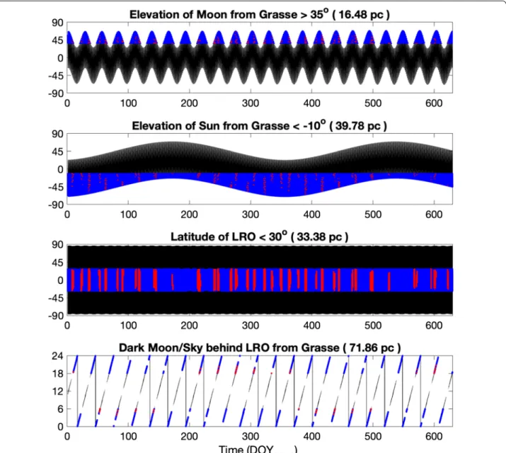
Second, the phasing of the LRO orbit with respect of Earth seasons and the lunar orbit limits the number and duration of the ‘passive’ attempts. This is illustrated in Fig. 7 where each geometrical constraint is not drastic in itself given it only limits observations to 16–72% of the time, but in combination is only satisfied ~ 0.6% of the time. Other factors, such as conflict with other instru-ment and spacecraft activities, position of the Earth and possible obstruction by the HGA or HGA boom, are not accounted for here, and would in reality further limit the number of possible passive attempts.
For this reason, more recently, we designed a number of LRO single-axis roll slews to align the -Z deck toward the Earth. This could increase the duration of the passes (from 5–10 min up to 40 min) and open up additional orbits for ranging opportunity periods. However, this cannot substantially increase the number of opportuni-ties. Slews can be precluded by other spacecraft activity and may not be possible if certain spacecraft rules can-not be followed (e.g., no occultation of the star trackers, power/thermal budget). Also, because of the relatively wide range gate, the detector can be overwhelmed by solar background photons, so LRO could not be observed
Table 1 Meteorological and atmospheric turbulence parameters during the successful LRO passes
Date (UTC) Temp. (°C) Humid. (%) Wind Seeing Isoplanatism Scintillation
index
2018/09/04 01:34 13 69 N/A 2.0″ 1.5″ 3.2%
2018/09/04 03:28 11 92 N/A 2.0″ 1.5″ 3.2%
2019/08/23 02:34 16.5 67 3.7 m/s 0.8″ 1.5″ 3.3%
against a bright Moon, limiting opportunities to local nighttime and face-on orbits.
Two‑way laser ranging observations
Setup
In the beginning of this experiment, orbits that offered real-time one-way Laser Ranging opportunities were preferred to be able to correct orbit errors and verify the telescope pointing. The goal was to range to LRO with co-boresighted low pulse energies at 532 nm wavelength to be detected by LOLA’s Detector 1 through the LRO LR telescope without the constraint in range gate, before the geometry allowed two-way ranging. Indeed, with pas-sive attempts, returns were only possible when LRO was near the lunar equator (± 20°), so there were ~ 10-min segments before and after these when LRO was still fly-ing over the nearside. However, real-time radio contacts from the USN or DSN were needed to have near real-time feedback. Given the LRO tracking schedule was not firmly known in advance, when opportunity planning between GSFC and Grasse was occurring, this led to the cancelation of a number of attempts.
Careful evaluation of the orbit prediction errors in the Grasse-LRO line-of-sight direction and regular one-way Laser Ranging by the Grasse station to LRO, conducted before the two-way opportunities, gave confidence that 1064-nm attempts with no preliminary 532-nm LR were
possible. High-quality orbit predictions were also some-times produced with GEODYN using the high-accuracy modeling used in orbit reconstruction (Mazarico et al.
2018), but the daily predictions supplied by the LRO pro-ject were generally sufficient.
Orbit predictions were provided for the observation days in the SPICE SPK format to the Paris Observatory, which produced Grasse-specific light time and azimuth/ elevation prediction files in the ‘Topocentric Prediction Format’ (TPF), accounting for the latest Earth Orien-tation Parameters provided by the International Earth Rotation Service (IERS). Surrounding the LRO two-way sessions, the Grasse station conducted regular LLR observations of the surface LRAs, to verify pointing and to allow comparison of the return rates.
Successful two‑way session in September 2018
The first successful two-way ranging occurred on Sep-tember 4, 2018 during passive opportunities. The first success was during the second attempt period that night, between 01:31 and 01:40 UTC. The following pass between 03:28 and 03:38 UTC also yielded echos. Regu-lar LLR to the Apollo 14 LRA was conducted prior and after the passes to provide a known baseline.
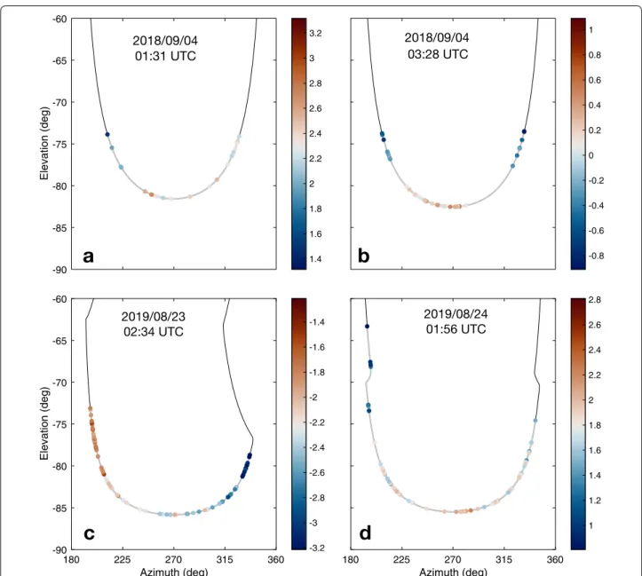
Figure 8a, b shows the path of the Earth in the LRO spacecraft frame, within the LRA FOV and outside of the HGA obstruction zone. The incidence angle of each
0 0.5 1 1.5 2 2.5 3 3.5 4 Time (hours) -200 -150 -100 -50 0 50 100 150 200 0 0.5 1 1.5 2 2.5 3 3.5 4 Time (hours) -400 -300 -200 -100 0 100 200 300 400 0 0.5 1 1.5 2 2.5 3 3.5 4 Time (hours) -3000 -2000 -1000 0 1000 2000 3000 0 0.5 1 1.5 2 2.5 3 3.5 4 Time (hours) 0 20 40 60 80 100 120 140 160 180 pred 229 pred 230 pred 231 pred 232 pred 233 pred 234 pred 235 0 0.5 1 1.5 2 2.5 3 3.5 4 Time (hours) 0 50 100 150 200 250 300 350 400 pred 228 pred 229 pred 230 pred 231 pred 232 pred 233 pred 234 0 0.5 1 1.5 2 2.5 3 3.5 4 Time (hours) 0 500 1000 1500 2000 2500 pred 241 pred 242 pred 243 pred 244 pred 245 pred 246 pred 247 Orbit di er ences (m) Total Position 2-way ranging periods Orbit di er ences (m)
LRO-Grasse Line of Sight
2018/09/04 2019/08/23 2019/08/24
Fig. 6 Evolution of errors of daily orbit prediction project deliveries. These were assessed as the difference with the reconstructed orbit. Total
position (dominated by the along‑track component) and Grasse‑LRO line‑of‑sight (LoS) discrepancies are shown. The periods where the two‑way laser ranging was performed are indicated with vertical dashed black lines
pulse on the array, useful to determine its effective OCS (Fig. 4), can be obtained from the telemetered LRO atti-tude information, and corresponds in these plots to the angle from −90° elevation (for which the line-of-sight to Grasse would be directly along the array normal).
Subsequent successful session in August 2019
Other attempts were made following the September 2018 success, but were either canceled due to bad weather or postponed due to station equipment maintenance and upgrades. During that time, the active slewing approach was developed and tested.
Mid-late August 2019 was very favorable from a geom-etry perspective, and a number of slews were com-manded over 7 days (one to two a day). The first two nights did not provide LRO returns despite good see-ing of the Apollo surface retro-reflectors. The next few nights were clouded out, but the weather cleared for the
last two nights. Two passes were successful on August 23rd between 02:34 and 02:46 UTC and on August 24th between 1:56 and 2:14 UTC. Figure 8c, d shows the path of the Earth in the LRO spacecraft frame during these two periods.
Analysis
We compared the ranging measurements to predicted values computed using the LRO trajectory, with the SPICE toolkit (Acton 1996). We used high-precision Earth orientation and the station meteorological data to compute range corrections. The residuals (observed minus computed) of the two-way light times show sys-tematic trends when using either predicted or recon-structed kernels, due to orbital errors, with biases on the order of a few nanoseconds and rates of 0.25–1.50 ns/ min. We removed these trends with a simple degree-3 polynomial fit. The detrended residuals are shown in Fig. 9. They show the intrinsic noise level over each of the four passes. The RMS values are ~ 166 ± 35 ps, which cor-responds to 2.50 ± 0.54 cm in one-way range.
Discussion and perspectives
The motivation for placing the LRA in lunar orbit onboard LRO was to provide a known pristine target for LLR systems to ascertain any degradation of the LRAs left on the surface. Independent combined analysis of echo return rates for both 532- and 1064-nm pulses at the Grasse station did not show what would be expected from the deposition of a fine layer or partial layer of dust on the surface corner cubes (Courde et al. 2017b).
Immediately surrounding the LRO ranging experi-mental periods, the Grasse station also ranged to these surface retro-reflectors. This significantly reduced the possible sources of variation in link margin due to tem-poral variations (less than few hours) in atmospheric conditions, Moon elevation, etc. The return rate for each pass was computed from the number of returned echos and the pass duration. Table 3 shows a summary of the relevant passes for the successful observations in 2018 and 2019.
In Table 3, the median value of the average return rate measured on A11 and A14 surface LRA (both are identi-cal) was 5.37%. As a matter of comparison, we computed the statistics of the average return rate per normal point from these two surface LRAs from Grasse LLR station over the year 2019 in Fig. 10: only 2% of the normal points reach this return rate or higher. This shows that condi-tions matching the successful two-way ranging sessions to LRO (e.g., Moon elevation, weather, dark background) are rare in the sample from Grasse LLR observations.
Here, we list all the known parameters that may affect the efficiency of the return from the LRA. First, the
Table 2 RMS of orbit differences between predictions and reconstruction in total position and along the line‑of‑ sight between Grasse and LRO. Orbit predictions and time periods are the same as in Fig. 6
Prediction RMS difference (m) in RMS difference (m) in Day of year Total
position Line‑of‑sight Total position Line‑of‑sight (DOY) Over 2 orbits Over ranging periods
For observations on 2018/09/04 (DOY 247)
2018/241 2347 1624 2326 322 2018/242 1397 955 1378 189 2018/243 937 626 911 123 2018/244 578 370 549 72 2018/245 384 226 347 44 2018/246 190 87 146 17 2018/247 86.8 4.1 28.3 3.9 For observations on 2019/08/23 (DOY 235)
2019/228 349 233 343 64 2019/229 120 80 114 22 2019/230 26 17 21 3.9 2019/231 13.9 8.3 10.2 1.8 2019/232 17.3 10.3 15.2 2.7 2019/233 13.2 7.5 11.8 1.9 2019/234 4.6 2.7 4.2 0.8
For observations on 2019/08/24 (DOY 236)
2019/229 159 111 152 40 2019/230 50 34 44 12 2019/231 34.1 22.7 29.2 7.8 2019/232 37.6 25.1 34.2 8.9 2019/233 31.8 21.0 29.1 7.4 2019/234 20.0 13.1 18.5 4.6 2019/235 11.9 7.4 11.0 2.5
incidence angle can strongly affect the return rate (see Fig. 4 for the optical cross-section of LRO’s LRA) and one must determine the incidence angle at LRO during the pass to take this into account. For the surface LRA, the lunar libration can be responsible for a variation of the incidence angle with a maximum amplitude of 8 degrees, which can reduce the return rate by up to 60% over the lunar cycle. Then, solar radiation effects on the efficiency of the surface LRA have been evaluated, and depending on the angle of the Sun direction to the nor-mal, the surface LRA can see a reduction in efficiency
up to 45% compared to night time conditions. During the passes considered here, all retro-reflectors were in the dark, and the effect of the Sun was therefore irrele-vant, but the libration of the Moon had to be taken into account. For instance, during 2019 passes, the libration of the Moon was around 6.75 degrees; according to the OCS of the surface LRA (Alley et al. 1969), this reduces their return efficiency by 50%. During the 2018 passes, the libration was 4.5 degrees, reducing their efficiency by 40%. The Earth atmosphere is also a factor that can affect the return rate measured at the LLR station.
Fig. 7 Evolution of key geometry parameters. These are shown for the LRO‑Grasse opportunities, between January 1, 2018 and September 22,
2019. The black lines give the complete time series of these parameters, and the blue lines the segments where the constraint on that parameter is satisfied. Their total duration relative to the time span is given in parenthesis as a percentage. The red lines indicate the periods where all four constraints are satisfied and thus when passive ranging may be attempted
Although the surface LRA were ranged to immediately before and after the LRO passes, the atmospheric con-ditions can change over relatively short time periods. Humidity at the level of the LLR station can vary rap-idly, as observed between the two LRO passes in 2018 (see Table 3). However, the return rate from LRO did not increase as much as on the surface LRA. The tur-bulence depends on the meteorological conditions and for example, for the 2018 passes, the median seeing value was about 2″ during the night, but the standard deviation of the seeing measured by the seeing monitor
between 1:20 and 2:18 UTC is around 0.46″. Such a variability, often observed with larger seeing values, can affect the instantaneous return rate at a timescale of minutes. Before comparing the return rate between retro-reflectors, even within a short time period, the stability of the atmospheric parameters must be veri-fied. Finally, all the passes were acquired with a dark background, i.e., without direct visual confirmation of the pointing from the lunar surface features (e.g., around the Apollo landing sites) to mitigate possible pointing errors from the operators.
-0.8 -0.6 -0.4 -0.2 0 0.2 0.4 0.6 0.8 1 180 225 270 315 360 Azimuth (deg) 1 1.2 1.4 1.6 1.8 2 2.2 2.4 2.6 2.8 -90 -85 -80 -75 -70 -65 -60 Elevation (deg) 1.4 1.6 1.8 2 2.2 2.4 2.6 2.8 3 3.2 180 225 270 315 360 Azimuth (deg) -90 -85 -80 -75 -70 -65 -60 Elevation (deg) -3.2 -3 -2.8 -2.6 -2.4 -2.2 -2 -1.8 -1.6 -1.4 2019/08/23 02:34 UTC 2019/08/24 01:56 UTC 2018/09/04 01:31 UTC 2018/09/04 03:28 UTC
a
b
c
d
Fig. 8 Path of the Grasse station as seen from LRO. Each figure is for the four successful passes. Shown in the LRO spacecraft bus frame, an elevation
of −90° represents the anti‑nadir direction which is also the retro‑reflector array normal. Elevations below ≈ −70° are within the LRA FOV. The points show the individual returns, colored by the residual (observed minus computed, in ns) with respect to the LRO trajectory (± 1 ns around the median)
Fig. 9 Time series of the detrended residuals for the four successful passes. The residuals and their RMS are computed from the time of flight
difference with the reconstructed LRO trajectory prediction made by the Paris Observatory Lunar Analysis Center (POLAC) and after a polynomial detrending (degree 3) to remove the remaining prediction errors
This first analysis shows the difficulty of ranging the LRO’s LRA. The successful passes were realized dur-ing some of the best statistically observed conditions for LLR ranging experiments. The amount of acquired data, sometimes while atmospheric conditions were not
so stable, is not yet sufficient to firmly conclude on the possible degradation of the surface LRA. To do so, the link budget must be improved. The Grasse LLR station is currently implementing a new laser solution with a nanosecond-pulse Nd:YAG laser, to provide up to 1 J of
Table 3 Statistics of the two‑way LLR passes obtained by Grasse during and immediately surrounding the LRO ranging experimental periods
Time (UTC) Target Δt (min) Number echos Range (km) Return rate (%) Hum. (%)
Date: 2018‑09‑04 01:31:00 LRO 8.20 25 366,726 0.51 69 01:51:45 A11 14.55 405 366,641 4.64 73 02:05:09 A14 11.23 506 366,241 7.51 77 02:44:04 A11 11.33 365 365,659 5.37 86 02:50:26 A14 3.78 155 365,408 6.83 89 03:28:00 LRO 9.40 43 364,568 0.76 92 03:45:49 A11 10.22 786 364,666 12.82 92 03:58:33 A14 12.75 1002 364,346 13.09 92 Date: 2019‑08‑23 01:52:22 A11 10.22 249 386,389 4.06 66 02:34:00 LRO 9.20 76 385,441 1.38 67 03:40:23 A11 10.98 113 384,881 1.71 62 03:51:03 A14 10.30 304 384,587 4.92 62 Date: 2019‑08‑24 01:52:59 A11 3.88 45 381,402 1.93 72 01:56:00 LRO 13.80 76 380,942 0.92 71 02:39:33 A11 10.37 35 380,525 0.56 76
Statistics of 2019 passes from Grasse to the Apollo 11 and Apollo 14 LRAs
median return rate for passes around the LRO 2-way passes
Fig. 10 Average return rate of LLR to surface LRAs. The distribution shows the average return rate per normal point from A11 and A14 LRA from
energy per pulse (vs. 0.3 J currently). The range preci-sion may be degraded but this experiment is primarily focused on the comparison of the LRA efficiency. The current observations have given us good knowledge of the conditions to perform successful two-way laser ranging to LRO’s LRA. This will help us prepare for a number of new attempts. As we accumulate returns in different geometry and configurations, but mostly improve the statistics with more passes, we will be able to perform a detailed quantitative study to ascertain the possible degradation of the surface LRA due to dust deposition.
The participation of other stations to this experiment would provide additional geometry and thus increase the number of ranging opportunities. Passive opportu-nities would for instance occur in different windows or seasons with southern hemisphere laser stations. This would require the participation of LRO of course and would constitute a very challenging experiment, espe-cially for stations working at 532 nm. To range to a small array like that of LRO, the station would need to be capa-ble of routine LLR observations under many observation conditions. It would however provide a first potential demonstration of direct time transfer of distant ground stations by laser links to a lunar orbiter.
Conclusion
We reported the first successful two-way laser ranging to a spacecraft at lunar distance. Several of these challeng-ing observations were made by the Grasse station to the retro-reflector array onboard LRO. Despite the small size of the LRO LRA, the laser echos could be clearly identi-fied and have an intrinsic range precision of < 3 cm. That precision level would be valuable for LLR, particularly at new lunar sites near the poles or limbs (Merkowitz 2010). Continued observations from Grasse to LRO are needed in the future to help quantitatively assess link margin dif-ferences and thus possible degradation due to dust depo-sition of the Apollo and Lunokhod LRAs.
Abbreviations
A11: Apollo 11; A14: Apollo 14; APOLLO: Apache point observatory lunar laser‑ranging operation; CC: Corner cube; CCD: Charge‑coupled device; CDDIS: Crustal dynamics data information system; CMOS: Complementary metal–oxide–semiconductor; DOY: Day of year; DSN: Deep space network; FOV: Field of view; G‑DIMM: Generalized differential IMage Monitor; GRAIL: Gravity recovery and interior laboratory; GSFC: Goddard Space Flight Center; HGA: High‑gain antenna; IERS: International Earth Rotation Service; ILRS: International Laser Ranging Service; LLR: Lunar Laser Ranging; LOLA: Lunar Orbiter Laser Altimeter; LRA: Laser retro‑reflector array; LRO: Lunar recon‑ naissance orbiter; LRT: Laser Ranging Telescope; OCS: Optical cross‑section; POLAC: Paris Observatory Lunar Analysis Center; RMS: Root mean square; RR: Retro‑reflector; SPAD: Single‑photon avalanche diode; TIR: Total internal reflec‑ tion; TPF: Topocentric prediction format; USN: Universal Space Network; UTC : Coordinated Universal Time.
Acknowledgements
We thank the LRO Operations team and the LRO Project for their support of this experiment. We also thank Mr. E. Aaron of KBRWyle for the fabrication of the LRA on LRO, and Mr. S. Wake for the optical testing of the LRA at GSFC.
Authors’ contributions
DS, MZ, XS and GN designed the LRO experiment and led the build of the LRA. XS and DC obtained experimental optical measurements of the LRA. PE, JMT, CC, JC, FL, DS, XS and EM set up the experiment to Grasse. JMT, CC, JC, MA, HM and NM defined the station operation plan and conducted the observation attempts. EM and DM identified the opportunities and planned them with the LRO team. MB and DM supported the design of the LRO slews required to bring the LRA in alignment. SB, TC and AB prepared station‑specific predic‑ tions for the telescope. EM provided the LRO orbit predictions for the two‑way tests and reconstructed the LRO orbit for analysis. CC, JC, SB, EM and VV analyzed the returned pulse data. EM, XS, DC, CC and JC prepared the initial manuscript. All authors provided feedback. All authors read and approved the final manuscript.
Funding
This work was supported by the NASA LRO Project, the Centre National de la Recherche Scientifique‑Institut National des Sciences de l’Univers (CNRS‑ INSU), and the Centre National d’Etudes Spatiales (CNES). This work was also supported by the LABEX Cluster of Excellence FIRST‑TF (ANR‑10‑LABX‑48‑01), within the Program “Investissements d’Avenir” operated by the French National Research Agency (ANR).
Availability of data and materials
The datasets used and/or analyzed during the current study are available from the corresponding author upon request.
Competing interests
The authors declare no competing interests.
Author details
1 NASA Goddard Space Flight Center (GSFC), Greenbelt, MD, USA. 2 Université
Côte d’Azur, Observatoire de la Côte d’Azur (OCA), CNRS, IRD, Géoazur, Nice, France. 3 Hexagon US Federal, Chantilly, VA, USA. 4 Observatoire de Paris‑
Meudon, Paris, France. 5 CRESST, University of Maryland, Baltimore County,
Baltimore, MD, USA. 6 Università di Bologna, Bologna, Italy. 7 Géosciences
Environnement Toulouse, Observatoire Midi‑Pyrénées, Toulouse, France. 8 Mas‑
sachusetts Institute of Technology (MIT), Cambridge, MA, USA. Received: 30 April 2020 Accepted: 30 July 2020
References
Acton CH (1996) Ancillary data services of NASA’s Navigation and Ancil‑ lary Information Facility. Planet Space Sci 44(1):65–70. https ://doi. org/10.1016/0032‑0633(95)00107 ‑7
Alley CO, Bender L, Chang RF, Currie DG, Dicke RH, Faller JE, Kaula WM, MacDonald GJF, Mulholland JD, Plotkin HH, Poultney SK, Wilkinson DT, Winer I, Carrion W, Johnson T, Spadin P, Robinson L, Wampler EJ, Wieber D, Silverberg E, Steggerda C, Mullendore J, Rayner J, Williams W, Warner B, Richardson H, Bopp B (1969) Apollo 11 Preliminary Science Report: 7 Laser Ranging Retroreflector. Technical report, NASA
Aristidi E, Ziad A, Chabé J, Fantéi‑Caujolle Y, Renaud C, Giordano C (2019) A generalized differential image motion monitor. Mon Not R Astron Soc 486(1):915–925. https ://doi.org/10.1093/mnras /stz85 4
Chabé J, Courde C, Torre J‑M, Bouquillon S, Bourgoin A, Aimar M, Albanèse D, Chauvineau B, Mariey H, Martinot‑Lagarde G, Maurice N, Phung D‑H, Samain E, Viot H (2020) Recent Progress in Lunar Laser Ranging at Grasse Laser Ranging Station. Earth Space Sci 7(3):000785. https ://doi. org/10.1029/2019E A0007 85
Courde C, Torre JM, Samain E, Martinot‑Lagarde G, Aimar M, Albanese D, Maurice N, Mariey H, Viot H, Exertier P, Fienga A, Viswanathan V. Satellite and lunar laser ranging in infrared. In: Proc. SPIE. Society of Photo‑Optical Instrumentation Engineers (SPIE) Conference Series, vol. 10229, p. 102290 (2017). https ://doi.org/10.1117/12.22705 73
Courde C, Torre JM, Samain E, Martinot‑Lagarde G, Aimar M, Albanese D, Exertier P, Fienga A, Mariey H, Metris G, Viot H, Viswanathan V (2017) Lunar laser ranging in infrared at the Grasse laser station. Astron Astrophys 602:90. https ://doi.org/10.1051/0004‑6361/20162 8590
Currie D, Dell’Agnello S, Delle Monache G (2011) A lunar laser ranging retrore‑ flector array for the 21st century. Acta Astronaut 68(7):667–680. https :// doi.org/10.1016/j.actaa stro.2010.09.001
Degnan JJ (2013) Millimeter accuracy satellite laser ranging: a review. American Geophysical Union, Washington, pp 133–162. https ://doi. org/10.1029/GD025 p0133
Dell’Agnello S, Boni A, Cantone C, Ciocci E, Martini M, Patrizi G, Tibuzzi M, Monache GD, Vittori R, Bianco G, Currie D, Intaglietta N, Salvatori L, Lops C, Contessa S, Porcelli L, Mondaini C, Tuscano P, Maiello M (2018) Next‑generation laser retroreflectors for GNSS, solar system exploration, geodesy, gravitational physics and earth observation. In: Sodnik Z, Cugny B, Karafolas N. (eds.) International Conference on Space Optics–ICSO 2014, vol. 10563, pp. 347–355. SPIE, Tenerife, Canary Islands, Spain (2018).
https ://doi.org/10.1117/12.23042 32. International Society for Optics and Photonics
Exertier P, Samain E, Bonnefond P, Guillemot P (2010) Status of the T2L2/Jason2 Experiment. Adv Space Res 46(12):1559–1565. https ://doi.org/10.1016/j. asr.2010.06.028
Exertier P, Samain E, Courde C, Martin N, Torre J, Oneto J, Geoazur, ML, Guillemot P, Léon, S.: T2L2: Five years in space. In: 2013 Joint European Frequency and Time Forum International Frequency Control Symposium (EFTF/IFC), pp 632–635 (2013)
He Y, Liu Q, Duan H‑Z, He J‑J, Jiang Y‑Z, Yeh H‑C (2018) Manufacture of a hollow corner cube retroreflector for next generation of lunar laser ranging. Res Astron Astrophys 18(11):136. https ://doi. org/10.1088/1674‑4527/18/11/136
Mao D, McGarry JF, Mazarico E, Neumann GA, Sun X, Torrence MH, Zagwodzki TW, Rowlands DD, Hoffman ED, Horvath JE, Golder JE, Barker MK, Smith DE, Zuber MT (2017) The laser ranging experiment of the Lunar Recon‑ naissance Orbiter: Five years of operations and data analysis. Icarus 283:55–69. https ://doi.org/10.1016/j.icaru s.2016.07.003
Mazarico E, Neumann GA, Barker MK, Goossens S, Smith DE, Zuber MT (2018) Orbit determination of the Lunar Reconnaissance Orbiter: Status after seven years. Planet Space Sci 162:2–19. https ://doi.org/10.1016/j. pss.2017.10.004
Merkowitz SM (2010) Tests of Gravity Using Lunar Laser Ranging. Living Rev Relativ 13(1):7. https ://doi.org/10.12942 /lrr‑2010‑7
Minott PO (1974) Measurement of the lidar cross sections of cube corner arrays for laser ranging of satellites. Technical report. https ://ntrs.nasa. gov/searc h.jsp?R=19750 01263 5
Müller J, Murphy TW, Schreiber U, Shelus PJ, Torre J‑M, Williams JG, Boggs DH, Bouquillon S, Bourgoin A, Hofmann F (2019) Lunar Laser Ranging: a tool for general relativity, lunar geophysics and Earth science. J Geodesy. https ://doi.org/10.1007/s0019 0‑019‑01296 ‑0
Murphy TW (2013) Lunar laser ranging: the millimeter challenge. Rep Prog Phys 76(7):076901. https ://doi.org/10.1088/0034‑4885/76/7/07690 1
Murphy JTW, Adelberger EG, Battat JBR, Carey LN, Hoyle CD, LeBlanc P, Michelsen EL, Nordtvedt K, Orin AE, Strasburg JD, Stubbs CW, Swanson HE, Williams E (2008) The Apache Point Observatory Lunar Laser‑ranging Operation: Instrument Description and First Detections. Publ Astron Soc Pac 120(863):20. https ://doi.org/10.1086/52642 8
Murphy TW, Adelberger EG, Battat JBR, Hoyle CD, McMillan RJ, Michelsen EL, Samad RL, Stubbs CW, Swanson HE (2010) Long‑term degrada‑ tion of optical devices on the Moon. Icarus 208(1):31–35. https ://doi. org/10.1016/j.icaru s.2010.02.015
Murphy TW, McMillan RJ, Johnson NH, Goodrow SD (2014) Lunar eclipse observations reveal anomalous thermal performance of Apollo reflectors. Icarus 231:183–192. https ://doi.org/10.1016/j.icaru s.2013.12.006
Noll CE, Ricklefs R, Horvath, J, Mueller H, Schwatke C, Torrence M. (2018) Infor‑ mation resources supporting scientific research for the international laser ranging service. J Geod. https ://doi.org/10.1007/s0019 0‑018‑1207‑2
Pearlman MR, Noll CE, Pavlis EC, Lemoine FG, Combrink L, Degnan JJ, Kirchner G, Schreiber U (2019) The ILRS: approaching 20 years and planning for the future. J Geodesy. https ://doi.org/10.1007/s0019 0‑019‑01241 ‑1
Smith DE, Zuber MT, Jackson GB, Cavanaugh JF, Neumann GA, Riris H, Sun X, Zellar RS, Coltharp C, Connelly J, Katz RB, Kleyner I, Liiva P, Matuszeski A, Mazarico EM, McGarry JF, Novo‑Gradac A‑M, Ott MN, Peters C, Ramos‑ Izquierdo LA, Ramsey L, Rowlands DD, Schmidt S, Scott VS, Shaw GB, Smith JC, Swinski J‑P, Torrence MH, Unger G, Yu AW, Zagwodzki TW (2009) The Lunar Orbiter Laser Altimeter Investigation on the Lunar Recon‑ naissance Orbiter Mission. Space Sci Rev 150(1–4):209–241. https ://doi. org/10.1007/s1121 4‑009‑9512‑y
Sun X, Smith DE, Hoffman ED, Wake SW, Cremons DR, Mazarico E, Lauenstein J‑M, Zuber MT, Aaron EC (2019) Small and lightweight laser retro‑ reflector arrays for lunar landers. Appl Opt 58(33):9259–9266. https ://doi. org/10.1364/AO.58.00925 9
Zuber MT, Smith DE, Zellar RS, Neumann GA, Sun X, Katz RB, Kleyner I, Matusz‑ eski A, McGarry JF, Ott MN, Ramos‑Izquierdo LA, Rowland DD, Torrence MH, Zagwodzki TW (2010) The Lunar Reconnaissance Orbiter Laser Rang‑ ing Investigation. Space Sci Rev 150(1–4):63–80. https ://doi.org/10.1007/ s1121 4‑009‑9511‑z
Zuber MT, Smith DE, Watkins MM, Asmar SW, Konopliv AS, Lemoine FG, Melosh HJ, Neumann GA, Phillips RJ, Solomon SC, Wieczorek MA, Williams JG, Goossens SJ, Kruizinga G, Mazarico E, Park RS, Yuan D‑N (2013) Gravity Field of the Moon from the Gravity Recovery and Interior Laboratory (GRAIL) Mission. Science 339(6120):668–671. https ://doi.org/10.1126/ scien ce.12315 07
Publisher’s Note
Springer Nature remains neutral with regard to jurisdictional claims in pub‑ lished maps and institutional affiliations.