HAL Id: hal-01987967
https://hal.uca.fr/hal-01987967
Submitted on 2 Feb 2021
HAL is a multi-disciplinary open access
archive for the deposit and dissemination of
sci-entific research documents, whether they are
pub-lished or not. The documents may come from
teaching and research institutions in France or
abroad, or from public or private research centers.
L’archive ouverte pluridisciplinaire HAL, est
destinée au dépôt et à la diffusion de documents
scientifiques de niveau recherche, publiés ou non,
émanant des établissements d’enseignement et de
recherche français ou étrangers, des laboratoires
publics ou privés.
A physical model of the bidirectional reflectance of
vegetation canopies. Part 1 : Theory
M.M. Verstraete, Bernard Pinty, R. E. Dickinson
To cite this version:
M.M. Verstraete, Bernard Pinty, R. E. Dickinson. A physical model of the bidirectional reflectance of
vegetation canopies. Part 1 : Theory. Journal of Geophysical Research, American Geophysical Union,
1990, 95 (D8), pp.11755. �10.1029/JD095iD08p11755�. �hal-01987967�
JOURNAL OF GEOPHYSICAL RESEARCH, VOL. 95, NO. D8, PAGES 11,755-11,765, JULY 20, 1990
A Physical Model of the Bidirectional Reflectance of Vegetation Canopies
1. Theory
MICHEL M. VERSTRAETE1Office for Interdisciplinary Earth Studies, University Corporation for Atmospheric Research, Boulder, Colorado
BERNARD PINTY 2 AND ROBERT E. DICKINSON
National Center for Atmospheric Research, Boulder, Colorado
An analytical expression for the bidirectional reflectance field of a vegetation canopy is derived from physical and geometrical considerations of the transfer of radiation through a porous medium. The reflectance pattern is shown to depend explicitly on the optical properties of the scatterers (for example, leaves), and on the structural parameters of the canopy, such as the statistical distribution of the orientation of these scatterers, the leaf area density, the size of the scatterers and their interspacing. This theory provides a simple and accurate way to understand the anisotropy of the radiation field over a vegetated surface. It can be useful for modeling applications (for example, the albedo is a by-product which can be numerically estimated), as well as for extracting some of the structural and physical properties of the surface. These applications are discussed in the accompany- ing paper (Pinty et al., this issue).
1. INTRODUCTION
Vast amounts of satellite remote sensing data on the state
and evolution of the surface of the Earth have been accu-
mulated over the last decade. NASA's projected Earth
Observing System (EOS) will significantly increase the size of this data base, not only with additional data, but also with improved spatial and temporal coverage, and enhanced
spectral resolution [NASA, 1988]. These developments pro-
vide unique opportunities for various scientific communities,
but the potential utilization of these data to retrieve quanti-
tative estimates of land surface properties is currently lim-
ited by various drawbacks inherent to remote sensing tech- niques. One such limitation lies in our inadequate
understanding of the physical processes governing the trans-
fer of radiation at the surface of the Earth. This translates
into a lack of physically based models to describe such
processes and to invert these data into useful information. It is well known that natural continental surfaces (bare
soils, vegetation canopies) reflect radiation quite anisotropi- cally. Satellite measurements therefore strongly depend on
both the position of the Sun and the position of the observer relative to the Sun, hence the term "bidirectional reflec- tance." This bidirectional reflectance field, however, cannot
be expressed as a function of the relative geometry of illumination and observation only (for example, the two
zenith angles and a relative azimuth angle), because it is also
dependent on the physical and the morphological properties of the observed surface. This fact alone is responsible for some of the major difficulties encountered in the process of
1Now
at Department
of Atmospheric,
Oceanic,
and Space
Sci-
ences, University of Michigan, Ann Arbor.
2permanently
at Laboratoire
Associ6
de M6t6orologie
Physique/
Observatoire de Physique du Globe de Clermont, Universit6 Blaise Pascal, Aubi•re, France.
Copyright 1990 by the American Geophysical Union.
Paper number 90JD00037. 0148-0227/90/90JD-00037505.00
interpreting data from one satellite and, a fortiori, when trying to compare or combine measurements from the same ecosystem taken with different satellite sensors.
A model of the bidirectional reflectance of natural surfaces
is therefore clearly needed. Various approaches have been used in the past to represent the anisotropy of the surface, including raytracing and Monte Carlo techniques [e.g., Kimes and Kirchner, 1982; Ross and Marshak, 1988], geo- metrical optics [e.g., Suits, 1972; Otterman, 1983], empirical functions [e.g., Walthall et al., 1985], semiempirical func- tions [e.g., Kieffer et al., 1977; Pinty and Ramond, 1986], and analytical solutions of the radiative transfer equations [e.g., Hapke, 1981; Camillo, 1987]. Each of these ap- proaches exhibits specific advantages and disadvantages, depending on the particular applications for which they were designed. Ideally, what would be needed to extract pertinent information on land surfaces from satellite remote sensing data is a universal, accurate, and computationally cheap physically based model of the bidirectional reflectance of porous surfaces.
The goal of this paper is to describe a physically based model for predicting the bidirectional reflectance field over a radiatively homogeneous scattering surface. Specifically, our theoretical development is designed to describe a homo- geneous full canopy composed of leaves. This model must be considered as the first necessary step toward a more realistic treatment of radiation scattering in this complex medium. The model is based on the scattering theory for a particulate media; it is kept as exact as reasonably possible, keeping in mind the necessary compromise between the need for an accurate description of the scattering process and for a simple analytical expression usable for the inversion of satellite remote sensing data. The application of this model to actual data sets is presented in a companion paper [Pinty et al., this issue].
This model follows the general approach developed by Hapke [1981, 1986]. Hapke's model was specifically de- signed to study planetary surfaces, using satellite bidirec-
11,756 VERSTRAETE ET AL.' CANOPY REFLECTANCE, 1
tional measurements of their reflectance fields. Implicitly, his model is applicable to homogenous semi-infinite media composed of uniformly distributed scatterers, as is generally the case for soil surfaces. However, as a result of the availability of water on land, over 65% of the continental areas on Earth are covered by vegetation, and exhibit surfaces with radiative properties significantly different from bare soil cases. In the simplest case of a fully covering homogeneous canopy, the radiation is mainly reflected and absorbed by leaves which, for the purposes of modeling, can be considered flat surfaces. These surfaces, however, may be preferentially oriented (in zenith or azimuth angle), de- pending on the plant species, and it has been shown that the reflectance of the canopy is quite dependent on both the zenith angle of illumination and the statistical distribution of leaf orientation (see, e.g., Ross [1981], Dickinson [1983], and Verstraete [1987, 1988]). The theory described below is a generalization of Hapke's model to account for the specific structure of a canopy, that is, the orientation of the leaves, as well as the characteristics of their geometrical arrange- ment in the canopy.
This paper also addresses another major theoretical point, namely, the mathematical expression of the combined trans- mission of the incoming and outgoing radiation. As will be seen shortly, the transmission of the scattered radiation in a porous medium is not independent of that of the incoming direct radiation: the two optical paths actually share a common volume, free of scatterers, near the scatterer that causes the reflection. Consequently, the optical depth along the combined path is reduced, and the total transmission becomes a function of the morphology of the medium. This
effect results in an enhanced reflectance in the direction of
illumination, and is known as the "hot spot" or the "oppo- sition effect." In practice, this increased reflectance ex- presses the total absence of apparent shadows to the sensor,
when the direction of observation and the direction of
illumination coincide, that is, when the source of radiation and the sensor are along the same optical path (see, e.g., Myneni et al. [1988]). This model therefore constitutes a direct attempt at providing a general analytical expression to relate some of the morphological properties of the canopy to the observed bidirectional reflectance field. Applications of this theory include the proper description of the reflectance (and in particular albedo) of a canopy of known physical and structural properties, as well as the capability to retrieve such information from remote sensing data.
2. SINGLE SCATTERING OF DIRECT RADIATION IN PLANT CANOPIES
Absorption of solar radiation by plant canopies and at the soil surface is of great interest to atmospheric modelers and climatologists, since it determines to a large extent the amount of solar energy effectively available for the climate system as a whole. This absorption of radiative energy at the surface of the Earth is also of concern to agronomists and biologists because it directly affects the physiology and productivity of plants.
While the quantity of radiation actually absorbed in a given environment is difficult to estimate directly, the radi- ation scattered by the surface can be measured with standard instruments, either locally or remotely. Since the absorbed and the scattered components are directly related through
the conservation of energy, it is customary to measure the scattered radiant energy and compute the absorption as a residual. It turns out, however, that many natural surfaces exhibit preferential directions for the reflection of solar radiation; in other words, the measured reflectance of such a surface depends not only on the nature and structure of the surface, or the intensity and position of the source of light, but also on the relative position of the observer. This represents a major inconvenience if the goal is to estimate the directional hemispherical reflectance (albedo) of the surface, since the reflectance must be measured and inte- grated over different viewing geometries. The bidirectional nature of the reflected radiation is an advantage, however, to the extent that it depends on (and therefore characterizes)
the structure of the surface. This allows the retrieval of
information on the surface by inversion of the measured reflectances in these viewing geometries.
This paper will focus on the theoretical treatment of the single-scattering component of the transfer of radiation through a vegetation canopy. This is amply justified by the facts that this component contributes approximately 90% of the total scattered radiation in the visible spectral band (that
is, with a wavelength shorter than 0.7 krm) and about 40% of
the radiation scattered in the near-infrared region, and that the single scattering of direct solar radiation contains the most useful information on the canopy structure, to the extent that the effect of multiple scattering is to smooth out such features. The inversion of actual data in the accompa- nying paper does take multiple scattering into account, however, following the improved formulation suggested by Dickinson et al. [1990].
2.1. Downward Transmission of the Direct Incident
Radiation
We start by considering a horizontally homogeneous (but possibly vertically inhomogeneous) canopy of finite depth h above the ground. Let z denote the vertical coordinate, increasing upward from an origin at the bottom of the
canopy. If 0• and &l are the zenith and azimuth angles of the
Sun, respectively, and if/•l - cos 01,
Tl(z)
=
exp
--•j exp
- kl(z)A(z)
dz (1)
is the transmission of direct solar radiation through the
canopy layers above level z. Here, rl(z) is the optical
thickness of the canopy above level z, A(z) is the leaf area
density,
in m 2 m -3, at level z in the canopy,
and kl(z) is the
extinction coefficient for direct radiation in this canopy:
K l(Z) (COS O1)Z
= = (2)
g i cos 01
where O l is the angle between the normal to a leaf and the direction of the Sun, and g l(z) = (cos O•)z is the average of
the cosine of this angle over all leaves at level z, a value that can be computed if the leaf orientation distribution function is known [e.g., Verstraete, 1987]. This average value is sometimes denoted G(•) [e.g., Ross, 1981].
If J0 is the direct solar radiation flux available at the top of
the canopy
(z = h), in W m -2 on a surface
pe•endicular
to
VERSTRAETE ET AL' CANOPY REFLECTANCE, 1 11,757
J0 Ial is the direct solar radiation flux available at the top of
the canopy,
in W m -2, on a horizontal
surface,
and J Ti(Z
)
is the direct solar radiation flux transmitted to level z without
interception in the canopy [Verstraete, 1987, p. 10,991]. Following Hapke's [1986, pp. 268-269] derivation, we express the flux of direct solar radiation transmitted to level z - dz in this canopy as
JTI(Z - dz) = Jol alTl(z) exp - dz
- dz
l
= Joia • Ti(z) exp - (3)
where
dr•(z) = (cos ©•)zA(z) dz = •(lA(Z) dz (4)
- dz
where K 1 is the average cosine of the angle between the
normal to the leaf and the direction of illumination (see (2)). The amount of direct solar radiation interacting for the first time with the canopy in the slab z to z - dz is therefore
JT•(z) - JT•(z - dz) = Joia •T•(z) 1 - exp ....
dri(z)
• Joia iTi(z) • = JoTi(z) dri(z) (5)
to the first order.
2.2. Scattering of Radiation in the Direction of an Observer
Consider now a directional light detector of size da, sensing the canopy through a small solid angle dfl (field of view). If it is located at a distance R from the canopy slab,
and if its orientation is characterized by a zenith angle 02 and an azimuth angle •b2, this detector samples an elementary
horizontal surface
R2d•
dA = • (6)
on the canopy slab, where Ia2 = cos 02. The amount of light
that illuminates the elementary volume dV = dAdz is given by
JoT•(z)dr •(z)dA (7)
Let to be the single-scattering albedo of the scatterers (mostly leaves), and P(g) the phase function of these scat- terers, assumed to be independent of leaf orientation. The phase angle g is the angle between the incoming and outgo- ing directions:
cos g = cos 0• cos 02 + sin 0• sin 02 cos (4•- 4•2) (8)
Then, if the sun flecks are assumed fiat, smooth and hori- zontal, that is, if we neglect the orientation of the intercept- ing leaf,
toP(g)
Jo T•(z)dv •(z)dA (9)
4re
is the density of radiation scattered with a phase angle g with respect to the direction of the Sun. The assumption of horizontal sun flecks is discussed below in section 2.3 and by Dickinson et al. [1990]. Furthermore,
toP(g) da toP(g) dfl
T•(z)dv•(z)dA = Jo T•(z)dr•(z) da
Jo 4
,r
•
4
,r
122
(10) is the amount of light scattered at the phase angle g in the
elementary volume dV of the sensor. Finally, if T2(z) is the
transmission of the scattered radiation on the optical path from the elementary canopy volume dV to the detector, the amount of light reaching the detector is
toP(g) dfl
Jo TI(z)d•'I(Z)T2(z) da (11)
4 ,r 122
and the light reaching the detector from all slabs in the canopy, per unit area and per unit solid angle, is given by
fo
h toP(g)
Jo TI(Z)T2(z) drl(Z)4•ria2
toP(g)
•0
h
= Jo Ti(z)T2(z) dri(z) (12) 4rria2
The bidirectional reflectance of this canopy, illuminated
from a direction (0•, •b•) by direct solar radiation, and observed from a direction (02, c32), is then obtained by
normalizing this expression by the incoming radiant power J0:
toP(g)
•o
h
p(01, qb•; 02, qb2)- Ti(z)T2(z) dri(z) (13)
4•ria2
2.3. Upward Transmission of the Scattered Radiation
For reasons that will be explained shortly, the transmis- sion of scattered radiation, in a direction (02, •b2) very far
from the incoming direction (01, qbl), is described by an
approximate expression similar to (1) for the incoming
radiation:
T2(z)
• exp
- --•2]
exp
- k2(z)A(z)
dz (14)
where •'2 is the approximate optical thickness along the return path, and k2(z) is the extinction coefficient appropriatefor the emerging direction:
2(z) (cos O2)z
= =
•2 cos 02
where O2 is the angle between the normal to the leaf and the
direction of observation.
This expression is only approximate because when the direction of observation is exactly the same as the direction
of illumination, the transmission T2(z) of the scattered light
should be unity, since any direct solar radiation capable of penetrating down to level z before being scattered must obviously be able to exit the canopy without further inter-
11,758 VERSTRAETE ET AL' CANOPY REFLECTANCE, 1
action with it when it is scattered back exactly in the
incoming direction. Moreover, direct solar radiation scat-
tered back in directions characterized by small phase angles
g, that is, close to its incoming path, has a high probability of escape from the canopy without further scattering by the
vegetation. The transmission of the outgoing radiation is therefore not independent from the transmission of the
incoming radiation. Reflectance is increased in the direction
of illumination because no shadows are visible in that
direction. This phenomenon is commonly observed on many porous surfaces such as soils and vegetation and is known as the "opposition effect" or "hot spot phenomenon."
From this qualitative discussion, it follows that the oppo- sition effect is a direct consequence of the structure of the canopy, and, in particular, that its angular extent is related to the shape of the "holes" between the leaves, that is, on the distribution of scatterer-free regions in the canopy as seen
from the direction of the Sun.
Describing the transmission of direct solar radiation in a scattering medium as a negative exponential (such as in (1)
and (14) above) is only a statistical statement that some diminishing fraction of the incoming photons will be able to penetrate further into the medium. Even though this law may be used to quantify the sunlit area as a function of depth in a canopy [e.g., Verstraete, 1987], it only describes the proportion of sun fleck area, not the number of sun flecks or their dimensions. Clearly, some additional parameter(s) on the canopy structure are needed to account for the hot spot, and they will of necessity be related to the geometry of the holes. Conversely, such parameter(s) will, in principle, permit the retrieval of information on the structure of plant canopies from an interpretation of the anisotropy of the reflectance field at small phase angles.
In the remainder of this section we derive a general expres-
sion of T2(z), for an arbitrary illumination and viewing geome-
try. This is achieved by finding an expression for the optical thickness of the return path (from the scatterer to the top of the canopy), which takes the above observations into account.
Consider a leaf of area at and of arbitrary orientation (0t, •bt), located at depth zt in the canopy, and partly illuminated ß by direct solar radiation. Let a] < at be the illuminated area cff thiq leaf. If •2 iq the angle hotween the normal tc• the leaf
and the direction of observation, the illuminated area effec- . tively viewed by the observer is given by a] cos {92, the
projection of the illuminated area in a plane perpendicular to
the direction of viewing. Furthermore, the observer would
see the same illuminated area if in fact the leaf was horizon-
tal, but had its lit area equal to a[ cos •2/c0s 02. It is
therefore possible to replace all partly lit leaves with arbi- trary orientation by equivalent (as far as the observer is concerned) horizontal leaves with a different illumination area, defined in such a way that the observer sees the same
result. The following theory is therefore derived for horizon-
tal leaves partially illuminated by the Sun.
For the purpose of deriving an analytical expression for
the optical thickness of the scattered radiation, we will further assume that the equivalent horizontal lit area is circular (we are interested in describing the amount of light scattered in the direction of the observer, not the shape of the sun flecks on the leaves). Let r be the radius of this small
horizontal circular illuminated leaf area at level Zl in the
canopy. The lit circle and the direction of illumination define
a cylindrical volume øV• in the canopy (Figure 1). Similarly,
the lit circle and the direction of observation define the cylin-
drical volume øV 2 in this canopy. These two cylinders share a common base and have the same height (h - zt) inside the
canopy; therefore they have the same total volume:
øV•
= øV2
= •rr2(h
- Zl)
(16)
If the two directions of illumination and observation are
identical, these two cylindrical volumes coincide. In all other
cases, they intersect only over a finite height above the level
of the scatterer, but since the two cylinders share the same lower base, they also necessarily always share some com-
mon volume
øV o = øV• Cl øV 2 (17) where f• designates the intersection of sets. The comple-
ment, that is, the fraction of øV 2 not in common with øV• is
(Figure 1)'
øV c = øV 2\øV o (18) where the symbol \ designates the subtraction operation for
sets.
Volume øV•, defined by the incoming beam of direct solar
radiation, is free of scatterers by definition. Consequently,
as long as the radiation scattered by the leaf in the direction of the observer remains within the volume oV o common to both cylinders, the optical thickness is zero (transmissivity is
one). The scattered radiation is, however, affected by the
usual optical depth as soon as it leaves the comm6n volume and proceeds to the observer within the volume oV c. Strictly speaking, each photon reaching the leaf and scattered in the direction of the observer has its own path length within oV o and øV c, but we will assume that globally, the effective optical depth for all incoming direct solar radiation scattered
toward the observer is a fraction of the optical depth that
would be appropriate in the absence of additional informa-
tion on the fractional path with zero optical depth, where the
fraction is simply the relative proportion of the volume not in common with
ß
2(z)-
iiC2l
I 2(z)
(19)
where ii•Vi[
stands
for the actual volume occupied
by the set
øV.
When the two directions coincide, the entire volume of the
cylinders is shared, øV o = øV 2 and øV c = 0, hence the optical depth on the return path is •'2 = 0, and the transmission of the scattered radiation in the direction of illumination is T2(z) = 1. Conversely, when the two directions are very different, the common volume øV o is relatively small, and øV c • øV 2, so that the optical depth in this case reduces to the asymptotic value •2. Equation (14) for the transmission of the scattered
radiation can therefore be rewritten
- = (20)
T2(z):
exp -•2
/ exp
and we are left with the problem of evaluating the ratio
II•rc
II/•r2 II for arbitrary angular
positions
of the Sun ana the
observer.
2.4. Optical Thickness of the Scattered Radiation We now define a new vertical coordinate, called z', as the height in the canopy relative to the height of the scatterer:
VERSTRAETE ET AL.' CANOPY REFLECTANCE, 1 11,759
(0•
, c)i
)
I (02
,½2)
'
I
ZT=h z=z.t z=O z•--h-z t z'--O(•=O)Fig. 1. Geometry of illumination and observation of a horizontal partially illuminated leaf. O is the center of a circular sun fleck on a horizontal leaf. OA defines the normal to the leaf, which is vertical in this case. OB and OC are the directions of illumination and observation, respectively, characterized by zenith angles 01 and 02. See text for
additional details.
z '= z- zt (21)
where zt is the height of the leaf above an arbitrary base
level, typically the ground.
Consider a horizontal plane a small variable distance z'
above the level Zl of the scatterer. This plane intersects the
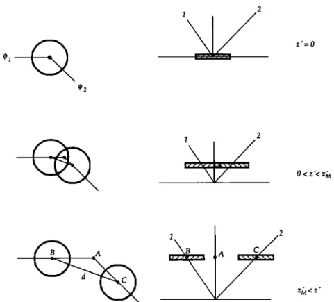
two cylinders described above and thereby defines two circles (Figure 2). In the general case where the illumination and observation directions are different, these circles intersect. As the height z' of this plane increases above the level of the scatterer, the area of intersection between the two circles
diminishes, until the level z' - z• is reached where the two
circles are tangent. For all levels above that, the two circles are disjoint. The volume common to both cylinders is defined by
the integral of this common area over the vertical distance z•. Let alo(Z' ) be the area common to both circles at a height
z' above the scatterer. It can be seen that
•o(Z') = 2r2(a -sin a cos a)
(22) where a - a(z') is the angle between the direction joining the two centers of the circles and the radius joining one center and the point at which the circles intersect (Figure 3).Obviously, a(z•) = 0 and alo(Z•) = 0 when the circles are tangent (or for all heights z' > z•), and a(0) = z'/2 and a/o(0)
= z'r 2 when
the two circles
overlap.
The angle a is a simple function of the relative altitude z' above the scatterer, once the illumination and viewing angles are specified. Referring again to Figure 1, it can be seen that in
the triangle OAB, 7I• = z' tan 0•, in the triangle OAC, A----C = z'
tan 02, and
in the triangle
ABC, B---C
2 = X-t•
2 + A----C
2 - 2AB
A½
cos (•b• - •b2). From these equalities, it results that the distance d between the centers of the two circles is given by
BC = d= z'[tan
2 0• + tan
2 02
- 2 tan 0• tan 02 cos (•b• - qb2)]
1/2= z'G
(23)
where
G = [tan
2 01 + tan
2 02- 2 tan 01 tan 02 cos (4•1 - 02)] 1/2
(24)
when these circles intersect, that is, for 0 -< z' -< zju. Clearly, if z' - z•u, the two circles are tangent and d = z•uG = 2 r, so
that
z,• = 2 r/G (25)
Furthermore, for 0 -< z' -< z•u, that is, at all heights for which
the two cylinders intersect, the distance between the two centers is also given by
d = 2r cos a (26)
Combining (23) and (26), it is possible to express a as a function of height:
a(z') = cos
-• (d/2r) = cos
-• (z'G/2r)
= cos
-1 (z'/z•) = cos
-• s
r
0 -< z' -< z•
(27)
a(z') = 0 z' >
where s r = z'/z• is a convenient nondimensional variable
taking up values between 0 and 1 over the vertical interval in which the cylinders intersect. Equation (22) can now be
rewritten
.•/o(S
r) = 2r2[cos
-! •' - sin (cos
-• sr)s
r]
0--<
s
r --<
1
(28)
.•/o(S r) = 0 otherwise
The volume To common to T1 and T2 but inside the
canopy can then be expressed as
f0
øVo = .•/o(Z') dz' (29)
where z• = min (z•u, z[r, z• = h - Zl being the height of the
11,760 VERSTRAETE E•I AL.' CANOPY REFLECTANCE, 1 2 42 z'-0
i
2
O<z'<z•Fig. 2. Top and side view of the intersection of the two cylinders representing the incoming and outgoing radiation beams, characterized by azimuth •bl and •b2. See text for additional details.
ested only in the optical depths within the canopy. Through
a suitable change of variables, this can equivalently be expressed as
2/-
alo(•) d• (30)
where •, = min (1, •t), with •t = z•r/z• = (h - Zl)G/2r similarly defined as the level of the top of the canopy in the
nondimensional variable •. Substituting (28) into (30), one
obtains
2r
•0C,
•o = '•
2r2[cos
-• • - sin
(cos
-• 0•] d•
(31) After some mathematical manipulations, this yieldsB C
Fig. 3. Description of the angles and surface involved in the computation of the volume common to the two cylinders. Refer to Figures 1 and 2 for notations, and to the text for additional details.
4r3
I
ø[/'
ø
= '•- •, COS
-1 •,
sin3(cøs-1
•r*)•]
- (1 -- •,2)1/2
_{_
-{-
(32)
3
The notations can be simplified somewhat by introducing a
new vertical coordinate y - h - zt, the depth of the leaf from the top of the canopy. We now have z• - y and •t - yG/2r.
The complex expression (32) can be interpreted as follows. ,-,, st, we note that as the •' ... *: oo• ... on direction (02, 4•2) tends toward the illumination direction (0•, 4•),
lim •, = •r= 0
2--)1
lim G - 0 (33)
2--)1
lim •o = •rr2y
= øg
• = øg
2
2-->1
as it should. Second, if the two directions of illumination and observation are separate enough, the two cylinders intersect over a limited height only, and if the scatterer is deep enough
in the canopy, the entire common volume •o should be
within the canopy. These circumstances, which can be
quantified as •r r = yG/2r -> 1, yield
8r 3
•o = • •', = 1 < •r r (34)
3G
Third, for leaf layers close enough from the top of the
canopy, or for observation angles near the illumination angles,
VI::I•RTI•AIXTI: I::T AI ' ('•&NII'•I:}V R!:I2I !::eTaNIt!::, ! !!,76!
Trr
Trr-
+ - sin3 COS-13
+
(35);*=;r =
since the cylinders defined by the illumination and observa- tion directions intersect outside of the canopy in this case. These are the conditions leading to the observation of a hot
spot, and it turns out that the common volume Y o, which
controls the extent to which the transmission is unity on the
return path, is simply a function of yG/2 r, which is nothing but
a nondimensional shape factor, the ratio of the depth of the leaf from the top of the canopy to the diameter of sun flecks on the leaves. The shape of this hole is a function of the illumination and viewing geometry, and this variation is entirely contained in G. This important fact is the basis for the expectation to be able to retrieve canopy structure information from hot spot observations in reflectance data sets, although further compu-
tations are needed before that result is achieved.
Comparing (34) and (35), and looking back at Figure 1, it
appears that the common volume inside the canopy Y o is the difference between the total volume common to Y1 and Y2,
and the volume common to the two cylinders outside of the canopy. The expression
IYrl [YrJ
cos-I - 1-[ [Yr]2]
i [
+ • sin3
cos-
1
(36)
in (35) is therefore the negative of the volume common to the two cylinders outside the canopy.
Having computed the volume common to both cylinders,
we now return to the problem of expressing the volume Y c
(equation (18)) needed to calculate the actual optical thick-
ness of the scattered radiation:
4r 3
øVc=
rrr2y
• [•',
cos
-1 •',- (1- •.2,)1/2
+ • sin
3 (cos
-1 •,) + •]
(37)
where •, = min (1, •r), as before. Using (19) and (16), the
optical thickness is
l 2
r2(z) = 1-•
[•', cos
-1 •', - (1 - •.2,)1/2
+-}
sin
3
(cos
-1
;,)
+
•]}•2(Z)
(38)
Again, in the special case where •r > 1, •, = 1 and these
equations reduce to
•/'c = 7rr2y
• •
8r 3 3Gß
2(z)
=
I
3rr•r4 ] •2(z)
(39)and it is seen that the correction to •2 becomes negligible when •r tends to large values, that is, when the two
directions are far from each other (G --> o•) or for deeper
layers (y = (h - Zl)'-> o•).
Substituting r2(z) back into (20) yields the value of the
transmission for the radiation scattered off a single leaf. The reflectance observed by an instrument outside the canopy is of course the sum of the contributions of all leaves, so that a final vertical integral needs to be performedß
3. BIDIRECTIONAL REFLECTANCE OF A CANOPY
As seen in the previous section, the optical thickness on the return path takes on different expressions at different depths in the canopy. Accordingly, the vertical integral in (13) can be rewritten as follows:
ooP(g)
foh
ß ...dy
p(01,
•bl,
02,
•b2)-
4,r/x2
.... dy + ' " dy = (p' + (40)
4,r/x2
c
where the first integral takes into account all canopy layers
which contribute strongly to the hot spot (•, = •r < 1), while
the second integral represents the contribution of deeper layers, for which the optical depth is always nonzero (•, = 1
< •r)- The variable Yc is given by
yc=min
(h,
z•)=min
(h,
2•) (41)
and represents a threshold level: All leaf layers between the
top of the canopy and Y c contribute directly to the hot spot
by having at least a fraction of the light reaching the observer with a transmission equal to one in the canopy, while deeper
layers (Yc < Y < h) are such that the transmission of
scattered radiation always has a nonzero optical depth over some fraction of the path.
Using (38), the first contribution becomes
p'(01, •bl; 02, •b2)-
øøP(g)
•oYCexp
[-glAy
]
4*r/x2
/Xl J
ß
exp 1 rryG •r cos
-1 + - sin 3 COS - 1 3 exp Ay 4,r/x2 1/2
ß
exp 1 rrG
/.•
2
COS
- 1
(1-[•r]2)
1/2+•sin3
(cos-liar])
+2•]}}dY
(42)
where r I (z) = t<l Ay, drl = l( 1Ady, and •, = •r. The
11,762 VERSTRAETE ET AL.' CANOPY REFLECTANCE, 1
For instance, the integral of the exponential of a single cosine is a Bessel function, and none of the tables of integrals we have consulted give any indication on the form of integrals even remotely resembling the one above. Since
the complication originates from the form of the optical thickness r2(z), it is reasonable to evaluate the relative
contributions of the four terms in (38), but none of them is
negligible with respect to the others in the range of values of
•,. On the other hand, it turns out that
2[
F(•',)
= •'T •'*
COS-I•'*
(1 •-2,)1/2_•
sin
3
(COS
-1
•',)
+-2]
3 3
(43) is almost a linear function of •, over the range of interest (0 < •, < 1), as can be seen from Figure 4. Since it is also
desirable to have F(0) = 1 and F(1) = 4/3rr so that the optical
thickness reaches exact values for extreme values of •, and
connects smoothly with the case •, = 1 < •r, we have
adopted the following parameterization:
P(•,) = 1-
1-
•,
(44)
which is also shown in Figure 4. This slight approximation
seems justified by the high degree to which F(•,) is linear, and by the appreciable simplification it brings to the mathe- matical development. We now have
r2(z)=
{1-
[1-
(1-3-•)•,]}•2(z
) (45)
Equation (42) can then be rewritten as follows: ,oP(g)
02, 4)2)-
4yr/62
foYC
exp
[-
tt
lAy]
/-62 .]
Conceptually, the size of the sun flecks on the leaves
diminishes with depth in the canopy. This presents a serious
1.0 0.8 0.6 0.4 0.2
1 I
I
I
_ _ I I I I 0.0 0.0 0.2 0.4 0.6 0.8 1.0 ZetaFig. 4. Comparison between the exact and approximate values of
the optical thickness on the return path (F(•,) versus P(•,)).
complication, however, and we are going to assume that the integrals in (40) can be evaluated with a constant value or r, representative of an average sun fleck. This point will be discussed further in the next section. Carrying out the integrals, the first contribution yields
wP(g)
foYC
[ •clAy
•c2Ay
p .... exp 4,r/62 /61 /62
+ 1- 1-•-ff•
• /621K1Ady
wP(g) - ••A 4•r/62ß exp
- 1 - •--• 2r/62
y2
+ 2 y dy
2/61toP(g)
4yr/62
t(
1A
[•(3)
1/2
exp
(b•)
ß eft + 0 where (47)3-•)
G•c2A
•c
1A
a = 1 - b - (48) 2r/62 2/61The second integral is somewhat simpler. Using the optical thickness given by (39), p" - exp Ay
4,r/62 yc
/61/62
(4 [2Ay_h
ß
exp
3•r
•'T/62/K
1A
dy
t( 1A exp . • 4•r/62 3rr G /62 (K1/62 + ti2/61)A[- Kl•2 + K2•i
-]Yc
/61/62 h (49)where •r has been replaced by its value yG/2r.
Collecting all the terms and simplifying wherever possible, the expression for the bidirectional reflectance of a canopy for single scattering can be written as
oo P ( g ) /(1/61 P(01, qbl; 02, qb2)-
K1/62
/61/62+
K2/61
4rr •1/62 + /<2/61(3)
1/2
exp
(b-•)
b b + exp . exp -G /62 /
/61/62
I K1/62+
K2/61
- exp Ah /61/62 (5O)where all variables and parameters have been defined ear-
lier. The bidirectional reflectance of a canopy is therefore given in terms of six physical quantities: w, the single- scattering albedo of the scattering particles (leaves); P(g),
the phase function describing the angular distribution of the scattered photons after a first interaction; r, the radius of an
average equivalent sun fleck, projected on an horizontal
surface in such a way that the observer "sees" the same
illuminated area; A, the leaf area density of the canopy, a measure of the density of leaf material; and the parameters K1 and K2, which describe the leaf orientation distribution for the illumination and viewing angles, respectively.
The bidirectional reflectance of shallow or sparse canopies is complicated by the contribution of the underlying soil, with its own anisotropy. Only deep (so-called semi-infinite)
canopies will be considered in the rest of this and the accompanying paper [Pinty et al., this issue] unless stated otherwise. In this case, the last term of (50) vanishes, and the contribution of the soil can be neglected.
To account for multiple scattering in the canopy, a con- tribution that is important in the near-infrared spectral
region, we followed the work of Dickinson et al. [1990].
Accordingly, the final expression for the bidirectional reflec-
tance of a deep canopy is given by
60 Kl• 1 P(01, •1; 02, •2)= • 4•r •l/X2 + ß [Pv(g)P(g) + H(• 1/• 1)H(•2/•2) - 1] where A •lg2 + •2gl
Pv(
g)
= 2 •1• 2
b b + expG
t Kl•2
d-
K2•l
ß exp l+x H(x) =1 + (1 - w)mx
(51) (52)The parameter a, used in Pv(g) to describe the hot spot, is directly proportional to the geometric factor G, which tends
to zero when the phase angle g tends to zero. This does not
cause any singularity in the expression, however, because
the difference in error functions tends to zero faster than the
exponential diverges. In fact, the expression Pv(g) varies
between 2 and 1 for all values of the illumination and
observation angles.
4. DIscussioN
From this derivation, it follows that the bidirectional
reflectance of an homogeneous plant canopy can be de- scribed physically in terms of six optical and structural parameters. We now discuss some important points relative
to the model and its physical interpretation.
First of all, it is important to remember that the radiation
reflected by a canopy (or any surface, for that matter) has only penetrated a finite depth below the surface. The infor-
mation retrieved from inverting the reflectances, using this or any other model of the surface, can therefore only yield
the optical and the structural parameters of the upper canopy
layers which actually affect the transfer of this radiation. If
the bulk of the solar radiation cannot penetrate deeper than some fraction of the height of the canopy stand, it will be impossible, as a matter of principle, to retrieve any informa- tion on the lower portions of this canopy from the reflec-
tances measured above the canopy. It is therefore difficult to
retrieve the leaf area index from remote measurements in the
solar spectral band, since either the canopy is very deep, in which case only the properties of the top can be retrieved, or the canopy is thin enough that even the lower leaf layers
affect the transfer of radiation, but then the contribution of
the reflectance from the soil must also be taken into account.
Another point to remember is that the canopy parameters A and r have been kept constant with height in the integrals
(47) and (49). The assumption on A is consistent with the
hypothesis of an homogeneous canopy; the one on r is more
of a limitation and implies that the reflectance from a large number of sun flecks of different sizes is equivalent to the
reflectance that would be observed if all the sun flecks had
the same average size.
Of course, the actual size and shape of the sun flecks are functions of depth in the canopy, and depend on the size and shape of the holes between the leaves. These, in turn, are determined by the relative positions of the leaves in the
canopy. As the beam of direct solar radiation penetrates the
canopy, it gets broken down into smaller beams by the upper
leaf layers, and each one of those smaller beams gets thinner due to the incremental blocking of additional leaves. It would be interesting, therefore, to relate the theoretical r used in the previous section to measurable quantities of the canopy. One possible line of reasoning could be as follows. Leaving aside the question of the number of sun flecks at
any particular depth in the canopy, let a(y) be the horizontal
cross section of one of those solar beams, that is, the connected area that would be illuminated by direct solar
radiation if a horizontal screen was placed at depth y in the
canopy. As discussed in section 2.3 and by Verstraete
[1987], this cross section a(y) decreases exponentially with
depth y in the stand:
a(y) = Ao exp (53)
•l /
where a0 is the area of the typical "hole" between the leaves at the top of the canopy. An estimate of the average value (a) of this area over a finite depth (Y t) can be defined as
Y'a(
y)
dy
aotx •(a) = = • (54)
•0
yt K1AYt
dywhere Y t is the depth in the canopy after which a negligible
fraction of the direct solar radiation is transmitted down-
ward. From this expression, a typical radius of such an area
11,764 VERSTRAETE ET AL ' CANOPY REFLECTANCE, 1
(r>
= [ rrt•
1Aytl L
K
1
•Yt
(55)
where r 0 is the radius of the "hole" between the leaves at the top of the canopy. Note that both (a) and (r) depend explicitly on the nondimensional product Ayt, which is in fact a ratio of two distances' Y t is a typical distance of penetration of direct solar radiation in the canopy, while A is
also the inverse of a typical distance between the leaves of a homogeneous canopy.
The relation between the parameter r in the model above
and the typical radius of the holes (r) is not simple, however,
because the size of a sun fleck on a leaf cannot exceed the
size of a leaf, by definition. To proceed further in this direction, one should adopt a particular model of canopy, to establish the nature of the relation between r, (r), and A. Clearly, as the number of leaves per unit volume or the size of the leaves increases, the typical dimension of the "holes"
between the leaves must decrease.
It is not so much the size of these voids that count, however, but rather their shape. Indeed, consider the fol-
lowing thought experiments: Let a canopy be described by ni leaves per unit volume, and let al be the area of a leaf. Furthermore, let x•, x2, x3 be the spatial coordinates of the
centers of these uniformly distributed leaves. If we compress the unit volume vertically in such a way that the horizontal
coordinates of the leaves remain unchanged (xl = x• and x• = x2), and that the vertical coordinate is mapped into x• = •x 3 with • < 1, and if additional leaves are then added in this portion of the unit volume at the new leaf density, then the
leaf area index is increased, the average horizontal distance between the leaves is unchanged, but the vertical distance of
penetration of light Y t is reduced. This is expected to
produce a broader hot spot peak.
If, on the other hand, the compression is done horizontally
(xl = •x•, x• = x2, and x• = x3), then the typical horizontal
distance between the leaves is decreased, but the vertical distance between leaves is not affected. The hot spot pro-
duced by such a canopy would be sharper. Finally, if the
number of leaves remains the same, but their area increases,
as is the case during the growing season, then both the penetration depth Y t and the average distance between the leaves change and the response of the hot spot will depend on the change in the shape of the voids between the leaves. An analogous experiment has been performed by Ross and Marshak [1988] using a Monte Carlo model, and their results
are consistent with our qualitative predictions.
As will be seen in the accompanying paper of Pinty et al. [this issue], (51) and (52) describe not only the general behavior of the bidirectional reflectance field of a canopy
with arbitrary physical and morphological properties, but
also correctly account for the hot spot phenomenon. It is
important to realize that the genuine contribution of this new model lies in the proper accounting of the joint transmission of solar radiation in the canopy, both over the downward incoming path and over the upward outgoing path. Indeed, the quantitative description of the hot spot phenomenon derives directly from the correct accounting of this joint transmission over all possible angles of illumination and
observations.
Pinty et al. [this issue] describe in detail the application of
this model to actual data sets and discuss the capability of the model to reproduce specific patterns in the data.
NOTATION
al Leaf area. ß
a/ Illuminated leaf area.
•/o Area common to the horizontal sections of W• and W 2 (equation (22)).
d Distance between the centers of the cylinders W• and W2.
da Size of the directional light detector (equation (10)). dA Elementary horizontal surface sampled by sensor
(equation (8)).
g Phase angle (equation (8)). G Geometric factor (equation 24)).
h Height of the canopy above the ground. H Function to account for multiple scattering.
J Direct solar radiation flux at the top of the canopy
on a horizontal surface.
J0 Direct solar radiation flux at the top of the canopy
on a surface perpendicular to the direction of the
Sun.
P(g) Phase function of the scatterer.
r Radius of the horizontal sun fleck.
T• Transmission of the downward radiation. T2 Transmission of the upward radiation. W• Cylinder of incoming radiation. W2 Cylinder of outgoing radiation.
W o Volume common to W• and W2 (equation (17)). W½ Part of W2 not in common with W• (equation (18)).
y Vertical coordinate, from the top of canopy down. z Vertical coordinate, from the ground up.
z' Vertical coordinate, from the scatterer up. a Angle of intersection (Figure 3).
•' Nondimensional vertical coordinate (equation (27)). •', Minimum value of •' (equation (30)).
•'r Height of the canopy in coordinate •'. 0• Illumination zenith angle.
02 Observation zenith angle.
O• Angle between the leaf normal and the illumination
direction.
O2 Angle between the leaf normal and the observation
direction.
K• Average cosine of angle between leaf normal and
illumination direction.
K2 Average cosine of angle between leaf normal and
observation direction.
A Leaf area density.
• Cosine of the solar zenith angle. •2 Cosine of the observation zenith angle.
p Reflectance of the canopy.
p' Hot spot contribution to the reflectance of the canopy.
p" Contribution to the reflectance of the canopy far
from the hot spot.
r• Optical thickness along the illumination direction. r2 Optical thickness along the observation direction. •2 Asymptotic value of the optical thickness along the
observation direction.
•b • Solar azimuth angle. •b2 Observation azimuth angle.
co Single-scattering albedo of the scatterers.
df• Solid angle of the field of view.
Acknowledgments. This research would not have been possible without the financial support of the European Space Agency (ESA),
VERST_n_•_ETE ET AL.' C'ANOP¾ RFFtI,ECTANCE• ! ! 1,765
the Centre National pour la Recherche Scientifique (CNRS), and the National Center for Atmospheric Research (NCAR) for B.P. Partial financial support for M.M.V. and R.E.D. was provided by NASA under grant NASA-S-56469. The National Center for Atmospheric Research is operated by the University Corporation for Atmo- spheric Research under the sponsorship of the National Science
Foundation.
REFERENCES
Camillo, P., A canopy reflectance model based on an analytical solution to the multiple scattering equation, Remote Sens. Envi-
ron., 23,453-477, 1987.
Dickinson, R. E., Land surface processes and climate--Surface albedos and energy balance, Adv. Geophys., 25, 305-353, 1983. Dickinson, R. E., B. Pinty, and M. M. Verstraete, Relating surface
albedos in GCMs to remotely sensed data, Agric. For. Meteorol., in press, 1990.
Hapke, B. W., Bidirectional reflectance spectroscopy, 1, Theory, J. Geophys. Res., 86, 3039-3054, 1981.
Hapke, B. W., Bidirectional reflectance spectroscopy, 4, The ex- tinction coefficient and the opposition effect, Icarus, 67, 264-280,
1986.
Kieffer, H. H., T. Z. Martin, A. R. Peterfreund, and B. M. Jakosky, Thermal and albedo mapping of Mars during the Viking primary mission, J. Geophys. Res., 82, 4249-4291, 1977.
Kimes, D. S., and J. A. Kirchner, Irradiance measurement errors due to the assumption of a LambertJan reference panel, Remote
Sens. Environ., 12, 141-149, 1982.
Myneni, R. B., V. P. Gutschick, G. Asrar, and E. T. Kanemasu, Photon transport in vegetation canopies with anisotropic scatter- ing, 1, Scattering phase functions in one angle, Agric. For.
Meteorol., 42, 1-16, 1988.
NASA, From pattern to process: The strategy of the Earth Observ-
ing System, EOS Sci. Steering Comm. Rep., vol. II, 140 pp.,
1988.
Otterman, J., Absorption of insolation by land surfaces with sparse vertical protrusions, Tellus, 35B, 309-318, 1983.
Pinty, B., and D. Ramond, A simple bidirectional reflectance model for terrestrial surfaces, J. Geophys. Res., 91, 7803-7808, 1986. Pinty, B., M. M. Verstraete, and R. E. Dickinson, A physical model
of the bidirectional reflectance of vegetation canopies, 2, Inver- sion and validation, J. Geophys. Res., this issue.
Ross, J., The Radiation Regime and Architecture of Plant Stands, 391 pp., W. Junk, Boston, Mass., 1981.
Ross, J., and A. L. Marshak, Calculation of the canopy bidirectional reflectance using the Monte-Carlo method, Remote Sens. Envi-
ron., 24, 213-225, 1988.
Suits, G. H., The calculation of the directional reflectance of a vegetative canopy, Remote $ens. Environ., 2, 117-125, 1972. Verstraete, M. M., Radiation transfer in plant canopies: Transmis-
sion of direct solar radiation and the role of leaf orientation, J. Geophys. Res., 92, 10,985-10,995, 1987.
Verstraete, M. M., Radiation transfer in plant canopies: Scattering of solar radiation and canopy reflectance, J. Geophys. Res., 93,
9483-9494, 1988.
Walthall, C. L., J. M. Norman, J. M. Welles, G. Campbell, and B. Blad, Simple equation to approximate the bidirectional reflec- tance for vegetative canopies and bare soil surfaces, Appl. Opt.,
24, 383-387, 1985.
R. E. Dickinson and B. Pinty, National Center for Atmospheric
Research, P.O. Box 3000, Boulder, CO 80307.
M. Verstraete, Department of Atmospheric, Oceanic, and Space Sciences, University of Michigan, Ann Arbor, MI 48109.
(Received July 13, 1989; revised December 26, 1989;