HAL Id: hal-00205123
https://hal.archives-ouvertes.fr/hal-00205123
Submitted on 27 Feb 2020
HAL is a multi-disciplinary open access
archive for the deposit and dissemination of
sci-entific research documents, whether they are
pub-lished or not. The documents may come from
teaching and research institutions in France or
abroad, or from public or private research centers.
L’archive ouverte pluridisciplinaire HAL, est
destinée au dépôt et à la diffusion de documents
scientifiques de niveau recherche, publiés ou non,
émanant des établissements d’enseignement et de
recherche français ou étrangers, des laboratoires
publics ou privés.
Distributed under a Creative Commons Attribution| 4.0 International License
Heat-Transfer and Mixing Enhancement by Vortex
Generators Used in Heat Exchanger-Reactors
Sébastien Ferrouillat, Patrice Tochon, C. Garnier, Hassan Peerhossaini
To cite this version:
Sébastien Ferrouillat, Patrice Tochon, C. Garnier, Hassan Peerhossaini. Heat-Transfer and Mixing
Enhancement by Vortex Generators Used in Heat Exchanger-Reactors. ASME/JSME 2003 4th Joint
Fluids Summer Engineering Conference, Jul 2003, Honolulu, United States.
�10.1115/FEDSM2003-45785�. �hal-00205123�
Heat-transfer and mixing enhancement by vortex generators used in heat
exchanger-reactors
S. Ferrouillat, P. Tochon, C. Garnier, and H. Peerhossaini
*CEA GRETh, 17 avenue des Martyrs, F-38054 Grenoble Cedex 9 – France
*
Laboratoire de Thermocinétique, CNRS-UMR 6607 Ecole Polytechnique de l’Université de Nantes,
Rue Christian Pauc, BP 50609, F-44306 Nantes Cedex 3 – France
ABSTRACT
Compact heat exchangers are well known for their ability to transfer a large amount of heat while retaining low volume and weight. The purpose of this paper is to study the potential of using this device as a chemical reactor, generally called a heat exchanger-reactor (HEX reactor). Indeed, the question arises: can these geometries combine heat transfer and mixing in the same device? Such a technology would offer many potential advantages, such as better reaction control (through the thermal aspect), improved selectivity (through intensified mixing, more isothermal operation and shorter residence time, and sharper RTDs), byproduct reduction, and enhanced safety. Several geometries of compact heat exchanger based on turbulence generation are available. This paper focuses on one type: vortex generators. The main objective is to contribute to the determination of turbulent flow inside various geometries by computational fluid dynamics methods. These enhanced industrial geometries are studied in terms of their thermal-hydraulic performance and macro-/micro-mixing ability. The longitudinal vortices they generate in a channel flow turn the flow perpendicular to the main flow direction and enhance mixing between the fluid close to the fin and that in the middle of the channel. Two kinds of vortex generators are considered: a delta winglet pair and a rectangular winglet pair. For both, good agreement is obtained between numerical results and data in the literature. The vortex generator concept is found to be very efficient in terms of heat-transfer enhancement and macro-mixing. Nevertheless, the micro-mixing level is poor due to strong inhomogeneities: the vortex generator must be used as a heat-transfer enhancement device or as a static mixer for macro- and meso-mixing.
INTRODUCTION
Compact plate-fin heat exchangers were initially developed in the ’40s in the aerospace industry to provide compact, light, highly efficient heat exchangers for gas/gas applications. These heat exchangers can provide secondary surfaces up to 90% of the overall heat transfer surface that lead to high heat transfer area per unit
potential application as a reactor. Indeed, the high mixing level and the high heat-transfer performance of turbulence promoters (such as vortex generators) contained in a compact heat exchanger makes this device potentially useful as a chemical reactor: heat-exchanger reactors (HEX reactors). This technology offers many advantages such as better reaction control (from the thermal point of view), improved selectivity (through intensified mixing, more isothermal operation and shorter residence time, and sharper RTDs), byproduct reduction and better safety. Indeed, although many traditional designs such as stirred tanks already incorporate heat transfer, in these there is a significant distance between the heat transfer device and the site of the chemical reaction. The aim of the HEX reactor is to annihilate this distance by supplying or removing the heat almost as rapidly as it is absorbed or generated by the reaction.
The development of such devices requires sizing tools to aid in the design and operation of the process. The thermal performance of heat exchangers is key to a global energy efficiency analysis. Furthermore, local analysis of flow and heat transfer conditions is also required for better characterization in terms of chemical reactors (mixing intensity and residence time distribution).
In this paper we focus on a potential technology (vortex generator) able to produce both heat transfer and mixing: a pair of delta winglets and a pair of rectangular winglets. These two types of turbulence promoters integrated in a heat exchanger have flexible design and high heat-transfer performance, and are potentially suitable for chemical reaction.
The aim of this paper is to provide specific comparisons to evaluate the accuracy of advanced numerical methods for flow and heat-transfer predictions inside HEX reactors with vortex generators where experimental data are available. Because of the complex flow structure in such geometries, their performance is generally determined experimentally. This paper first reviews their thermal-hydraulic performance, based on data from the literature and computational fluid dynamics (CFD) analysis. Then the mixing capacity of these turbulent promoters is determined using CFD methods. The pertinent choice of turbulence models according to the
1 VORTEX GENERATORS
Inside a duct channel, vortices can be generated by flow separation that make the fluid rotate continuously around their rotation axis. This phenomenon can be used to enhance convective heat transfer.
1.1 Design and physical phenomena
Most of the vortex generators (VGs) designed on the above concepts have been manufactured by punching or embossing the wall of a plate or a channel. The present study focuses only on the punched geometry. The three-dimensional nature of VG allows a large variety of configurations. Two different basic vortex generator forms are investigated here: delta forms and rectangular forms. Wing and winglet VGs, mounted and punched VGs, single rows, double rows and periodic arrays of VGs were investigated. This paper focuses on rectangular winglet pairs (RWP) and delta winglet pairs (DWP), as shown schematically in Figure 1 and Figure 2 respectively.
Figure 1: Geometry of a Rectangular Winglet Pair [5]
Figure 2: Geometry of a Delta Winglet Pair [5]
Vortex generators, while remaining attached to the plate at the base, protrude into the flow at an angle of attack to the main flow direction. The two most important dimensionless geometric parameters that control vortex characteristics (e.g. heat transfer and pressure loss enhancement) are this angle of attack and the area ratio between VG and the channel span.
The basic principle of vortex generators is based on the cutoff of the thermal boundary layer developed along the wall and also on the heat removal from the wall to the core of the flow by means of large-scale turbulence. An efficient way to enhance heat transfer is to generate counter-rotating vortices by means of pairs of delta winglets or rectangular winglets (Figure 1, Figure 2 and Figure 6).
(Single elements have been shown to have lower performance [1], [2].) With VGs, the transition to turbulence occurs at lower Reynolds numbers than in a plane channel flow and the turbulence intensity is increased ([3]). Vortex generators seem appropriate heat-transfer devices in flows with intermediate Reynolds numbers. Delta forms are slightly more efficient than rectangular forms [2].
Figure 3: Physical phenomena in VGs [4].
Transverse vortices may be distinguished from longitudinal ones. The predominance of one over the other depends on the angle of attack β [5]. Transverse vortices have their axes transverse or perpendicular to the flow direction and are consistent with two-dimensional flow. Longitudinal vortices have their axes in the streamwise or flow direction and always lead to three-dimensional flow. For β≤ 65° the vortex system is dominated by longitudinal vortices, while for β ≥ 70° transverse vortex structures are dominant. For RWP and DWP, it has been shown that longitudinal vortices are more efficient than transverse ones when pressure losses are taken into account [5-6]. Heat transfer does not increase substantially for angles of attack larger than 65°.
1.2 Overall performance of vortex generators
Pairs of winglets (triangular or rectangular) have been studied experimentally and numerically by Tiggelbeck et al. [2]. The triangular winglet height is equal to the channel height while the rectangular winglet height is only half the channel height. Available experimental data, in terms of Nusselt number, friction factor and Colburn factor, are summarized in Table 1.
The Colburn factor is defined by:
3 1 Pr Re Nu j=
where the Reynolds number Re is given by µ ρUdh
= Re
The fanning friction factor is defined by:
2 2d U L P f h ρ ∆ =
The j/f ratio for vortex generators is satisfactory (j/f > 0.39) and within the range of Reynolds numbers tested (2000-8000), the heat transfer and pressure drop enhancement are proportional to Re0.3.
Table 1: Performance of VGs at Re = 4600 and β =30° [2]
Geometry Nu Nu/Nu0 f/f0 j j/f
Triangular 24.76 1.49 1.91 0.0061 0.39
Rectangular 24.26 1.46 1.85 0.0059 0.39
2 NUMERICAL MODELS AND PROCEDURE
A numerical simulation of an air flow inside a duct with one pair of winglets was performed using FLUENT software with different turbulence models.
2.1 Turbulence model
Several turbulence models were used in this study. The (k−ε) model and the large eddy simulation (LES) were tested with different model laws: standard [7], RNG [8] and Realizable [9] for the (k−ε) model and Smagorinsky [10-11] and RNG [12] for the LES model.
The standard (k−ε) model [7] is a semi-empirical model based on model transport equations for the turbulence kinetic energy ( k ) and its dissipation rate (ε). The model transport equation for k was derived from the exact equations, while the model transport equation for ε was obtained by phenomenological reasoning and bears little resemblance to its mathematically exact counterpart. In deriving the (k−ε) model, it was assumed that the flow is fully turbulent and the effects of molecular viscosity are negligible. The standard (k−ε) model is therefore valid only for fully turbulent flows. The RNG-based (k−ε) turbulence model [8] is derived from the instantaneous Navier-Stokes equations by using a mathematical technique called the “renormalization group” (RNG) method. The analytical derivation yields a model with constants different from those in the standard (k−ε) model, and additional terms and functions appear in the transport equations for (k−ε).
In addition to the standard and RNG-based (k−ε) models described above, FLUENT software also provides the so-called Realizable (k−ε) model [9]. The term “Realizable” means that the model satisfies certain mathematical constraints on the normal stresses that are consistent with the physics of turbulent flows. Unsteady simulations were carried out using a Smagorinsky [10-11] and RNG [12] LES turbulence model with several time steps. The main results of these simulations are presented below.
2.2 Mixing model
Knowledge of the turbulence energy dissipation rate, ε , is needed to predict the micro-mixing ability of a device. The average energy dissipation rate, Φ , is related to the volumetric flow rate Q , the pressure drop ∆ , the fluid density P ρ and the working volume
M V by: ρ M V P Q∆ = Φ ( 1 )
Φ is expressed per unit mass of fluid in the channel, so that V is M
the total internal volume less the volume of the metal internals. The working volume is the total internal volume multiplied by the fractional liquid holdup e .The dissipation rate Φ can be divided into turbulent dissipationε, caused by gradients in the turbulent
velocity fluctuations, and direct dissipationE , due to gradients of D the mean velocity. Thus:
D
E + =
Φ ε (2 )
where Φ is averaged over the volume V . M ε and E generally D
vary widely with position in the channel
The pressure drop is related to the friction factor by:
h d L Q f P ρ 2 4 2 = ∆ (3 )
The mixing efficiency can be determined by the value of the pressure drop and the turbulence energy dissipation ε (m2.s-3):
Φ − = Φ = ε 1 ED η ( 4 )
For the numerical computations, the above method can be used to evaluate the mixing efficiency. Thus one must estimate the pressure drop ∆ and the turbulence energy dissipation P ε by using a
)
(k−ε or a LES model. Then the pressure drop calculation lets one compute the average energy dissipation rate, Φ , and the mixing efficiency can be deduced.
2.3 Geometry and grid
The main dimensions of the two geometries are given in Figure 4, Figure 5 and Table 2. The geometries are meshed with tetrahedral elements for the delta winglet pair and hexagonal elements for the rectangular winglet pair. The overall number of elements is about 250,000 for the DWP and 150,000 for the RWP.
Figure 4: Rectangular vortex-generator geometry and notation
Table 2: Geometrical dimensions of the winglets Tiggelbeck [3] RWP (30 °) RWP (65 °) DWP (65°) Channel height H 20 mm 6,35 mm 6,35 mm 5 mm Channel length L 15H 15 H 15 H 15 H Channel breadth B 5H 5H 5H 5H Fin area AF 30 000 mm2 3 024 mm2 3 024 mm2 1875 mm2 Angle of attack β 65° or 30 ° 30° 65° 65° Height of VG z H H H H Span of VG l 2H 2H 2H 2H Area of VG VG A 800 mm² 80 mm² 80 mm² 50 mm² VG F A A 37.5 37.5 37.5 37.5 v x H H H H s 0.2 H 0.2 H 0.2 H 0.2 H 3 NUMERICAL RESULTS
3.1 Results for RWP at Re = 4600 and 30° angle of attack
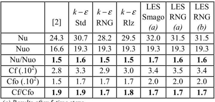
Several turbulence models were tested for a rectangular winglet pair at Reynolds number 4600 and angle of attack 30°. The main dimensions of this geometry are shown in Table 2. The (k−ε) and LES models were tested with different model laws: standard, RNG and Realizable for the (k−ε) model and Smagorinsky and RNG for the LES model. Furthermore, for the LES turbulent model, unsteady simulations were carried out with several time steps. These results focus on the influence of the number of time steps and are summarized in Table 3.
Table 3: Results for a RWP at Re = 4600 and β = 30°
[2] −ε k Std ε − k RNG ε − k Rlz LES Smago (a) LES RNG (a) LES RNG (b) Nu 24.3 30.7 28.2 29.5 32.0 31.5 31.5 Nuo 16.6 19.3 19.3 19.3 19.3 19.3 19.3 Nu/Nuo 1.5 1.6 1.5 1.5 1.7 1.6 1.6 Cf (.102) 2.8 3.3 2.9 3.0 3.4 3.5 3.4 Cfo (.102) 1.5 1.7 1.7 1.7 2.0 2.0 2.0 Cf/Cfo 1.9 1.9 1.7 1.8 1.7 1.7 1.7
(a) Results after 5 time steps (b) Results after 40 time steps
Comparing the above numerical results with experimental data from [2], it can be seen that the (k−ε) and the LES models satisfactorily predict heat transfer enhancement (Nu/Nuo) and drag coefficient enhancement (Cf/Cfo).
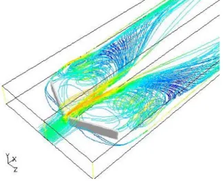
The RNG and Realizable (k−ε) turbulent models seem to give the best results. Indeed, they have specific terms to take into account swirl and adverse pressure gradients A comparison of the LES computations after five and 40 time steps leads to the conclusion that the generation of longitudinal vortices is actually a quasi-steady phenomenon. Indeed, there is no significant difference between these two simulations in terms of heat transfer and drag enhancement. As expected, both RNG or Realizable (k−ε) and LES simulations describe a pair of counter-rotating vortices in the wake of the winglets (Figure 6), but the standard (k−ε) model does not correctly predict counter-rotating vortices. These vortices are created by the difference of pressure between the pressure side and suction side of the wings.
Figure 6: Streamlines in the wake of a RWP (30°)
3.2 Effects of the angle of attack for RWP
The influence of the angle of attack β was also studied with the best turbulence models. Using a LES model with a RNG subgrid scale model and a RNG (k−ε) model, computations on the rectangular winglet pair were carried out for Reynolds numbers 4600 and angle of attack 65°. These results are also compared with those obtained previously for 30° (Table 4).
Table 4: Effect of angle of attack on Nusselt enhancement and drag coefficient
30° 65°
[2] )(k−ε LES [2] (k−ε) LES
Nu/Nuo 1.5 1.5 1.6 1.7 1.8 1.8
Cf/Cfo 1.9 1.7 1.8 3.3 3.8 3.4
Comparing the above numerical results with experimental data from [2] shows that the LES simulation gives good predictions in term of heat transfer and pressure losses for both angles. The RNG (k−ε) model strongly overestimates the pressure drops. Indeed, a bibliographic survey shows that for high attack angle, the flow behaviour in the wake of a VG moves from longitudinal to transverse vortices. Thus (k−ε) models can no longer predict that kind of strong anisotropic flow pattern. Thus, the LES model is the
only one able to describe qualitatively and quantitatively the flow behaviour for various angles.
For both results, heat transfer and drag coefficient increase with angle of attack. Moreover, the LES computation shows the transition domain between transversal and longitudinal vortices for a 65° angle of attack [5]. Indeed, contrary to Figure 6, which shows a predominance of longitudinal vortices for 30° angle of attack, Figure 7 shows that both longitudinal and transversal vortices exist.
Figure 7: Streamlines in the wake of a RWP (65°)
3.3 Effects of Reynolds number for RWP
According to the results obtained for RWP at two different angles of attack, the RNG-LES turbulence model is the only one able to produce satisfactory information for mainly longitudinal vortices (30°) or mainly transverse ones (65°). Therefore, this model was used to study the effects of Reynolds number (2000-8000) at an angle of attack of 65°. The results are then compared with available data (Figure 8 and Figure 9).
0 1 2 3 4 5 6 0 1000 2000 3000 4000 5000 6000 7000 8000 9000 Re Cf/Cfo Tiggelbeck et al. 1994 FLUENT LES
Figure 8: Drag coefficient vs. Reynolds number for RWP LES computations show satisfactory prediction of the drag coefficient (Cf/Cfo) for Reynolds numbers lower than 6000 (Figure 8). However, for Reynolds numbers higher than 6000, a difference arises between experimental data from [2] and LES computations. This difference may be due to the coarseness of the mesh at this Reynolds number, where the boundary layer is thicker. The heat- transfer prediction seems to be satisfactory with a LES computation for the entire turbulence flow regime. Nevertheless, this simulation is not good for Reynolds numbers of 2000, i.e. for a laminar flow
regime. Therefore, LES computations overestimate the heat transfer for Reynolds number below 2300 (Figure 9).
0 0.5 1 1.5 2 2.5 0 1000 2000 3000 4000 5000 6000 7000 8000 9000 Re Nu /Nu o Tiggelbeck et al. 1994 FLUENT LES
Figure 9: Nusselt enhancement vs. Reynolds number for RWP
3.4 Effects of Reynolds number for DWP
Using the LES turbulence model with a RNG subgrid scale model, simulations for the delta winglet pair were carried out for different Reynolds numbers (2000-8000) and a 65° angle of attack.. This geometry leads to the formation of a pair of counter-rotating vortices in the wake of the winglets.
0 0.5 1 1.5 2 2.5 3 3.5 4 4.5 0 1000 2000 3000 4000 5000 6000 7000 8000 9000 Re Cf/Cf 0 Tiggelbeck et al. 1994 FLUENT L.E.S.
Figure 10 : Drag coefficient vs. Reynolds number for DWP
0 0.5 1 1.5 2 2.5 0 1000 2000 3000 4000 5000 6000 7000 8000 9000 Re Nu /Nu 0 Tiggelbeck et al. 1994 FLUENT L.E.S.
Figure 11 : Nusselt enhancement vs. Reynolds number for DWP Comparing the LES results with experimental data from [2], one can readily observe the satisfactory predictions of drag coefficient (Cf/Cf0) and heat transfer (Nu/Nu0) by these computations (Figure
The drag coefficient in DWP configuration is of the same order of magnitude as in RWP. Indeed, the friction enhancement varies in the two cases from 2.7 to about 4. A small heat-transfer enhancement was observed between DWP and RWP (1.5 instead of 1.4 at Re = 2000; 2.2 instead of 2.0 at Re = 8000).
4 MIXING PERFORMANCE
Mixing performance was studied for a RWP at Re = 4600 and β = 30° with a RNG (k−ε) turbulent model. The (k−ε) computation lets us plot mixing efficiency versus x/H (Figure 12).
0% 10% 20% 30% 40% 50% 60% 70% 80% 90% 100% 0 1 2 3 4 5 6 7 8 9 10 11 12 13 14 15 x/H M ixi n g E ff ici en cy ( % ) RWP
Figure 12: Turbulent energy dissipation rate vs. x/H for a RWP at Re = 4600 and β = 30°
The rectangular winglet pair significantly increases the turbulent energy dissipation rate and thus mixing efficiency, which is greatest close to the VG level and decreases downstream. The high mixing efficiency at the outlet of the channel is due to the large local turbulent energy dissipation rate and thus the large inhomogeneity in the channel generated by longitudinal vortex. Indeed, vorticity along the flow direction reaches a high level (5000 s-1) at the core of
longitudinal vortices (Figure 13). In other words, the circumferential velocity value is of the same order of magnitude as the bulk velocity. This large circumferential velocity implies an increase of shear stress on the wall. These high values of vorticity and circumferential velocity imply a high turbulent energy dissipation rate and thus high mixing efficiency.
Temperature contours for several cross-sections along the channel (Figure 14) show the macro-mixing generated by RWP. These vortices turn the flow field perpendicular to the main flow direction and enhance mixing between the fluid close to the fin and that in the middle of the channel.
Figure 13: x-vorticity for various cross-sections along the channel for RWP at Re = 4600 and β = 30°
Figure 14: Temperature contours for various cross=sections along the channel for RWP at Re = 4600 and β =30°
5 CONCLUDING REMARKS
Numerical simulations of vortex generators with advanced turbulence models and refined mesh give reliable qualitative and quantitative results. The present study improves our knowledge of turbulent flow, heat transfer and the mixing ability of compact heat-exchanger geometries. By using RANS and the large eddy simulation turbulence model, steady and unsteady results were obtained. For the two vortex generators considered here, the computations with a refined mesh give satisfactory results: the underlying physical phenomena are described and the main geometrical parameters and their effect on turbulence are identified. For heat-exchanger applications, unsteady computation with a large number of time steps provides no extra information, since the vortices generated are almost steady.
Different numerical models were tested and LES models were validated for a wide range of Reynolds number and attack angles. Thus this methodology is now available for geometry optimisations such as the lateral and longitudinal winglet placement to provide a given turbulent energy dissipation rate in the winglets’ wake. This work has shown the utility of advanced numerical methods for optimisation of compact heat-exchanger geometries; they are now available as a tool for design engineers.
NOMENCLATURE F A Fin area, m2 VG A VG area, m2 B Channel width, m
Cf Drag coefficient, dimensionless
Cp Pressure coefficient, dimensionless
e fractional liquid holdup, dimensionless
D
E Direct dissipation, m2.s-3
h
d Hydraulic diameter, m
f Fanning friction factor, dimensionless
H Channel height, m
j Colburn factor, dimensionless
l VG span, m
L Channel length, m
Nu Nusselt number, dimensionless
Q Volumetric flow rate, m.s-1
U Flow velocity, m.s-1
M
V Working volume, m3
s Distance between tips of winglet pair, m
v
x Distance of wingtips from the channel entrance, m
z VG height, m
β Angle of attack, °
P
∆ Pressure drop, Pa
ε Turbulent energy dissipation, m2.s-3
η Mixing efficiency, dimensionless
µ Dynamic viscosity, Pa.s
ν
Kinematic viscosity, m2.s-1ρ Fluid density, kg.m-3
Φ Average rate of energy dissipation, m2.s-3
REFERENCES
1. M. Fiebig and T. Güntermann, 1993, A class of high
performance compact fin-plate heat exchangers elements, Transport Phenomena in Thermal Engineering, Begell House, pp. 926-931.
2. S. Tiggelbeck, N.K. Mitra and M. Fiebig, 1994, Comparison of wing-type vortex generators for heat transfer enhancement in channel flows, J. of Heat Transfer, 116, pp. 880-885.
3. S. Tiggelbeck, N.K. Mitra, and M. Fiebig, 1993. Experimental investigations of heat transfer and flow losses in a channel with double rows if longitudinal vortex generators. Int. J. Heat and Mass Transfer, 36 (9), pp. 2327-2337.
4. M. Fiebig, P. Kallweit and N.K. Mitra, 1986, Wing type vortex generators for heat transfer enhancement. I.H.T.C., 6, pp. 2909-2913.
5. M. Fiebig, 1995, Vortex generators for compact heat Exchangers, Journal of Enhanced Heat Transfer, 2 (1-2), pp. 43-61.
6. J.I. Yanagihara and K. Torii, 1990, Heat transfer
characteristics of laminar boundary layer in the presence of vortex generators, Proc. 9th IHTC, 6, pp.323-328
7. B.E. Launder and D.B. Spalding, 1972. Lectures in
Mathematical Models of Turbulence. Academic Press, London, England.
8. V. Yakhot and S.A. Orszag, 1986. Renormalization group analysis of turbulence: I. Basic theory. J. Sci. Computing, 1, pp. 1-51.
9. T.H. Shih, W.W. Liou, A. Shabbir and J. Zhu, 1995. A new k-ε eddy-viscosity model for high Reynolds number turbulent flows -- model development and validation. Computer Fluids, 24 (3), pp. 227-238.
10. U. Schumann, 1975. Subgrid scale model for finite difference simulations of turbulent flows in plane channels and annuli. J. Comput. Phys, 18, pp. 376-404.
11. J.S. Smagorinsky, 1963. General circulation experiments with the primitive equations: I -- The basic experiments. Mon. Weather Rev, 91, pp. 99-164.
12. A. Yakhot, S.A. Orszag, V Yakhot and M. Israeli, 1989. Renormalization group formulation of large-eddy simulation. J. Sci. Computing, 4, pp. 139-158.
![Figure 2: Geometry of a Delta Winglet Pair [5]](https://thumb-eu.123doks.com/thumbv2/123doknet/13071129.384227/3.892.103.364.436.624/figure-geometry-delta-winglet-pair.webp)
![Table 1: Performance of VGs at Re = 4600 and β =30° [2]](https://thumb-eu.123doks.com/thumbv2/123doknet/13071129.384227/4.892.490.819.659.788/table-performance-vgs-β.webp)