HAL Id: lirmm-02476015
https://hal-lirmm.ccsd.cnrs.fr/lirmm-02476015
Submitted on 8 Sep 2020
HAL is a multi-disciplinary open access
archive for the deposit and dissemination of
sci-entific research documents, whether they are
pub-lished or not. The documents may come from
teaching and research institutions in France or
abroad, or from public or private research centers.
L’archive ouverte pluridisciplinaire HAL, est
destinée au dépôt et à la diffusion de documents
scientifiques de niveau recherche, publiés ou non,
émanant des établissements d’enseignement et de
recherche français ou étrangers, des laboratoires
publics ou privés.
Manipulators Interacting With an Unknown
Environment
Nabil Zemiti, Guillaume Morel, Alain Micaelli, Barthélemy Cagneau,
Delphine Bellot
To cite this version:
Nabil Zemiti, Guillaume Morel, Alain Micaelli, Barthélemy Cagneau, Delphine Bellot. On the Force
Control of Kinematically Defective Manipulators Interacting With an Unknown Environment. IEEE
Transactions on Control Systems Technology, Institute of Electrical and Electronics Engineers, 2010,
18 (2), pp.307-322. �10.1109/TCST.2009.2022170�. �lirmm-02476015�
On the Force Control of Kinematically
Defective Manipulators Interacting
With an Unknown Environment
Nabil Zemiti, Guillaume Morel, Alain Micaelli, Barthélemy Cagneau, and Delphine Bellot
Abstract—In this paper, the problem of force feedback control of kinematically defective manipulators (KDMs) is considered. KDMs are robot manipulators that have fewer joints than the dimension of the space in which their end-effector moves. It is well known that controlling the end-effector velocity of an -joint KDM can be easily solved by appropriately selecting components of the output twist, thus squaring the control problem. On the contrary, we show that such a component selection approach is not appro-priate in general to solve the force control problem for KDMs. In particular, for advanced force control applications, such as coma-nipulation, where the contact geometry is not known in advance, the selection of the wrench components leads to a lack of passivity, which in turn may induce instability. This instability does not arise from the system dynamics. Rather, it can be viewed as a new form of kinematic instability. Moreover, by formulating the problem in the joint space, we show how to properly design a stable force con-troller for KDMs subject to arbitrary external forces applied to their end-effector. Furthermore, we propose several implementa-tions for pure force control and damping control. Experimental re-sults with a kinematically defective laparoscopic comanipulator il-lustrate these propositions.
Index Terms—Defective manipulators, force control, kinematic constraints, passivity, surgical robotics.
I. INTRODUCTION
N
OWADAYS, customized robots have been built for dedi-cated tasks in order to exploit their kinematic properties. Many of these robots have fewer joints than the dimension of the space in which their end-effector moves. In the literature [2], [3], these robots are called kinematically defective manipulators (KDMs). Their particular geometry makes them more adapted to a specific task, and leads to reduced costs.For example, endoscopic surgery requires the manipulation of an instrument through a fulcrum point, which is the entry
Manuscript received February 07, 2007; revised October 17, 2008. Manu-script received in final form April 27, 2009. First published June 30, 2009; cur-rent version published February 24, 2010. Recommended by Associate Editor M. de Mathelin. A portion of this work was presented in ICRA’06, Orlando, FL, May 2006.
N. Zemiti was with the Université Pierre & Marie Curie-Paris6, UMR 7222, Institut des Systèmes Intelligents et Robotique, Paris F-75005, France. He is now with the Université Montpellier II, LIRMM Laboratory, F-34392 Montpel-lier, France.
G. Morel, B. Cagneau, and D. Bellot are with the Université Pierre & Marie Curie-Paris6, UMR 7222, Institut des Systèmes Intelligents et Robotique, Paris F-75005, France (e-mail: [email protected]).
A. Micaelli is with the Laboratoire Commande et Interface Homme-Machine, CEA-LIST/DTSI/SCRI, Fontenay-aux-Roses F-92265, France.
Color versions of one or more of the figures in this paper are available online at http://ieeexplore.ieee.org.
Digital Object Identifier 10.1109/TCST.2009.2022170
point to the patient’s body through his/her skin. This imposes a 2 degrees-of-freedom (DoFs) planar constraint, and has motivated the design of several instrument holders with 4 DoFs (see, e.g., [4]–[6]). Also, a number of 4 or 5 DoFs robots are commercially available for industry (e.g., LRMate 100iB, Fanuc Robotics, http://www.fanuc.co.jp/), education (e.g., Ericc3, http://www.cybernetix.fr/), or research applications (e.g., WAM, http://www.barrett.com/).
Velocity control of KDMs is easy to derive: instead of con-trolling the full end-effector twist using the jacobian pseudo-in-verse, which is known in the literature to possibly lead to phys-ically inconsistent results [7]–[9], a reduced parameterization can be used by appropriately selecting some of the twist com-ponents. This approach allows for squaring the control problem and preserves the passivity of the system, as it will be detailed in Section IV.
Considering now the force control problem of KDMs, it has been shown in [10], [11] for grasping manipulators that not all the trajectories of the end-effector can be controlled nor arbi-trary contact forces can be applied. This induces difficulties in controlling the overall system. Indeed, as it will be shown in Section III, a KDM is a hyperstatic system that is, if the robot end-effector was embedded to the environment, one could not predict the applied wrench at the end-effector given a torque ap-plied at the joints. An explicit model of the environment is thus mandatory to solve this problem, as it has been presented in [3]. The force control problem considered in this paper concerns advanced applications such as surgical robotics and comanipu-lation, where arbitrary wrenches are applied to the end-effector, and are actively produced by one or several operators. Conse-quently, the use of the environment model shall be avoided.
To solve the force control problem for KDMs without having to model the environment, one can think that the component selection might be used, here again, for squaring the control problem. Unfortunately, we will show in this paper that this naive approach leads to a lack of passivity, which, in turn, may lead to a new form of kinematic instability when the contact ge-ometry changes.
This has motivated our research to consider the problem of force control applied to KDMs subject to arbitrary external forces, i.e., without any environment model, and establish the necessary and sufficient conditions for a passive, thus kinemat-ically stable, component selection.
Although this work does not propose any new structure for the force controller (a Jacobian Transpose controller, projecting a 6-D error into the joint space, can be finally used), its
elty lies in a constructive rule helping the selection of the force components for KDMs, which is based on a formal proof of pas-sivity. This new fundamental rule shows that the component se-lection shall respect the robot kinematics rather than the contact geometry. It is thus quite straightforward to apply knowing the robot kinematics. This allows us to propose a controller which is stable for any kind of external wrenches, even when the con-tact geometry is unknown. An illustrative example is taken for a minimally invasive surgery robot assistant, emphasizing stable response to forces exerted both inside the patient and outside the patient, while using a single force sensor.
The remainder of this paper is organized as follows. In Section II, an ongoing research overview and a formulation of the force control problem for KDMs are presented. In Section III, we further detail the notations and the robot models used in the paper. In Section IV, the component selection approach is applied to the velocity control of KDMs, and a passivity analysis is proposed. In Section V, we consider the problem of pure force control applied to KDMs and establish the basic passivity properties of two different force projection methods. In Section VI, these results are extended to damping control of KDMs. In Section VII, we provide experimental results to a particular KDM, which is a comanipulator for force feedback minimally invasive surgery. Finally, Section VIII provides a summary and discussion of the results, together with perspectives.
II. RELATEDWORK
Stability problems raised by component selection has been early reported in [12] and [13] where it has been shown that the kinematic stability of the hybrid position/force control method proposed by Raibert and Craig [14] is very dependent on the geometry of the manipulator.
The component selection has been pointed out in [15] and [16] as another significant factor for force control stability. In-deed, the authors have shown that the force controlled manipu-lator may become unstable if the force-controlled directions are not carefully selected with respect to the manipulator configu-ration. In [9], [17], [18], it has been shown that the component selection approach leads to physically inconsistent results and may induce the kinematic instability of the systems if a transla-tion or change in unit of the coordinate frame is performed. All these studies do not explicitly consider the possibility for the robot to be kinematically defective.
The kinematic instability problem has been identified in [19] as a result of an inappropriate formulation of the hybrid position/force control scheme when using component selection approach. The authors have proposed a kinematically stable hybrid position/force scheme, where the task specification (selection of the force-controlled direction) is based on an orthogonal projection approach instead of a conventional se-lection matrix. However, the orthogonal projection approach used for force control has been criticized in [17]. Furthermore, a counterexample has been given in [20], where the modified projection method proposed in [19] is proven to possibly fail. The alternative solution proposed in [20] consists in specifying the hybrid task using a dynamic projector. This approach
Fig. 1. One DoF robot comanipulating a heavy load with human operators.
conserves the passivity of the controller and thus guarantees the kinematic stability of the hybrid position/force control scheme. However, since the dynamic projector is calculated using the manipulator model, an error in the estimation of this latter may affect the stability of the system.
In [17], [18], [21], instead of a conventional selection matrix, kinestatic filters completely based on the environment model have been developed. These filters possess invariant properties with respect to Euclidean translations and changes in units which lead to the physical consistency of the system and thus guarantees the kinematic stability of the hybrid position/force control scheme. But they cannot be used when the environment model is not known.
The force selection problem considered in this paper differs, here again, from the problem studied within the hybrid posi-tion/force control paradigm. In hybrid posiposi-tion/force control, the force selection (or force filter) is designed from an explicit geometric description of the contacts (see [22] for a broad overview of hybrid control). Rather, here, such a geometric description shall be avoided in order to be able to deal with arbitrary wrenches applied to the end-effector. Indeed, as pre-viously mentioned in Section I, this research targets advanced applications where contacts may occur at different locations, and are actively produced by one or several operators.
The force selection problem under consideration can thus be described as follows: given a non-singular joint KDM, which end-effector is subject to arbitrary external wrenches, how to appropriately select components of the measured interaction wrench and servo them to a desired value so that the system remains kinematically stable? The answer to this question shall be established carefully, as illustrated in the trivial following example.
Consider a one rotating joint robot, that comanipulates a heavy load together with one or several human operators, as depicted in
Fig. 1. Assume that the desired behavior for the load is to be transparent, i.e., not to resist to the forces applied by the op-erators. In terms of control, this behavior can be achieved by a force feedback controller, with a desired force equal to zero. Assume also that one can measure all the components of the external wrench applied to the robot, i.e., in this planar case, , along and and the measured moment (at point ) along . With a 1 DoF robot, it is not possible to servo all the three measurements to a desired value. Therefore, the com-ponent selection paradigm consists, for example, in arbitrarily
selecting a force component along in order to built the force error
where is the reduction matrix that allows for the construction of a 1-D error from the wrench error.
Note that, in the general 3-D case, is an matrix con-nected to the classical selection matrix through
which, for the above example, writes
Due to the construction of the error, the force controller will pro-vide the same corrective motion for any external forces along . Whether this force is applied by operator or operator (see Fig. 1) cannot be distinguished by the controller. Therefore, the system cannot be stable for both operators. Indeed, in order to ensure stability, the controller should produce corrective mo-tions with opposite signs in response to the same force applied by operator or along .
This trivial example shows that the arbitrary component se-lection approach applied to force control of KDMs may lead to instability.
Obviously, the problem depicted in Fig. 1 can be solved by servoing the joint torque rather that the selected force compo-nent along , as any measured positive joint torque shall produce a positive joint velocity, without depending on where the force is applied. In other words, if the reduction matrix was chosen to be , then the above stability problem would be solved. Therefore, we are facing a kinematic stability problem, that only depends on the robot kinematics and the selection matrix.
III. MODELING
A. Kinematic and Static Models of KDMs
A robot with independent joints is considered, with denoting the joint positions. Furthermore, the pose of the robot
end-effector evolves in .
A kinematically defective manipulator is characterized by . For such a robot, one cannot control independently each component of the end-effector velocity , which is a vector grouping the coordinates of the end-effector linear and rotational velocity vectors. As a matter of fact, one has
(1) where is the Jacobian matrix of the manipulator and denotes the joint velocity vector regrouping either angular velocity components (rotational joints) or translational velocity components (prismatic joints).
The matrix is not square, thus, one cannot specify ar-bitrarily a desired velocity and compute the corre-sponding joint velocity .
Similarly, the force transmission model can be obtained by applying the virtual power principle, together with (1), which leads to, [23]
(2) where is the generalized joint force vector,1while
groups the coordinates of the end-effector wrench (force and moment) equivalent to . Again, is not controllable from , as is not square.
It is important to note that the force control problem funda-mentally differs from the velocity control problem.
Indeed, assume that a desired velocity is specified such that belongs to the range space of , noted , (a condition to ensure that can be achieved). Assume also that the robot is not in a singular configuration. Since the null space of , noted , has a null dimension, one can compute according to (1) the unique joint velocity vector corresponding to . Applying at the robot joints will necessarily generate at the robot end-effector.
On the other hand, if an arbitrary vector of is specified, (2) allows the computation of a corresponding joint torque
. However, applying this computed torque results in an equivalent wrench that verifies, according to (2)
(3) As the dimension of the null space of is not null, (3) does not guarantee that the resulting wrench is equal to . Rather,
the general solution is for to lie in ,
i.e., the resulting wrench equilibrates with the desired wrench , [24].
In fact, we are facing an hyperstatic system with an under-de-termined force control problem. Consequently, an explicit model of the environment may be used to solve the indetermi-nacy which will be avoided in this paper.
B. Linearized Robot Dynamics
As noticed in the introduction, the problem under considera-tion only relies on the kinematics of the robot and the force com-ponent selection. Here, the dynamics is not an issue. Therefore, in order to allow for a simplified analysis, a linearized model will be used for the robot dynamics. It is well known that the general form of an -joint robot dynamics in contact with the environment can be written as [25]
(4) where it follows:
• is the positive definite, symmetric inertia matrix; • is a vector grouping the Coriolis and centrifugal
joint torques;
1In the following, for shortness, generalized joint forces will be referred as
joint torques. However, the reader should keep in mind that this vector may
group either torques or forces, depending on the nature of the joints (rotation or translation).
• is a vector grouping the dissipative (friction) joint torques;
• is a vector grouping the gravity joint torques; • is the command vector for the joint torques;
• is the joint torque corresponding to
an external wrench applied by the environment to the robot (by convention, denotes, in the following, the wrench applied by the robot to the environment).
It is assumed in the next that, at the lowest level of the controller, a proportional velocity feedback is used in order to partly lin-earize the robot dynamics
(5) where is a symmetric, positive definite matrix of velocity feedback gains, (respectively, ) is a compensa-tion for the gravity (respectively, the Coriolis and centrifugal) joint torques, and is the new command vector for the joint torques. From a mechanical point of view, can be viewed as an additional viscous friction term. If chosen high enough, this term will be dominant. If, additionally, the compensation terms are supposed to be precise enough, a simplified model can be used
(6) Furthermore, it will be assumed in the next that the robot moves in a neighborhood of a given joint configuration , so that the variation of can be negligible and the model can be linearized by setting constant, [26]. Note that, this linearization is valid in a rather large neighborhood of when high gear ratio transmission is used (i.e., when the inertia matrix has the particularity of being diagonal dominant and mostly constant over the workspace, [27]). In the experi-mentations shown in this paper, this assumption is verified since the used surgical robot has a high gear ratio transmission.
The resulting linearized model of (4) writes
(7) where is the Laplace complex variable.
Again, this model is valid only locally, around an average configuration . Note that the purpose of the model lineariza-tion is only to allow for the use of linear tools for passivity anal-ysis in the rest of the paper. This simplification does not influ-ence the problem under study, that concerns kinematic stability. Moreover, even when not linearized, the robot dynamics can be shown to be passive [24].
Finally, when it will be necessary for the passivity analysis, the kinemato-static transmission models will be linearized as well, by simply setting
(8)
with .
C. Passivity
When considering a robot interacting with its environment, the stability properties depend not only on the robot dynamics, but also on the environment dynamics. In advanced applications
of force control, such as force feedback teleoperation or coma-nipulation, one cannot assume for a known model for the en-vironment. Therefore, a useful tool for the stability analysis of such systems is passivity analysis. Here, the basic idea is to pro-vide a controlled system such that the interaction port between the robot and the environment, i.e., the transfer between the ex-ternal wrench and the twist is passive.2 Although this condition is quite conservative, it provides a formal guarantee that, when coupled to passive environments, the system will re-main stable.
In practice, considering an LTI system, with an input and an output , the system is passive if, and only if, the real rational transfer matrix such that is positive real (PR). In turn, positive realness can be checked by the following prop-erty [29].
1) Property 1: Let be a linear transfer function, let , , denote the poles of all the elements
of , and let , , denote the pure
imaginary poles of all the elements of . The transfer is Positive Real if, and only if:
1) ;
2) , is of multiplicity 1, and the associated residue matrix is hermitian, positive semidefinite (PSD). The matrix can be computed as
if is finite (9) and
if is infinite (10) Note that a zero of is considered as a pole at the infinity.
3) is PSD, for any
.
For mechanical systems interacting with each other, the input-output variables are the forces ( or ) and the velocities ( or
). Quite usefully, either the impedance transfer function or the admittance transfer function can be checked to be PR in order to prove the system passivity [28]. For example, one can check for the robot passivity by considering its admittance
with: (11)
Here, the positive realness of can be verified straightfor-wardly invoking Property 1.
IV. VELOCITYCONTROL OFKDMS
In this section, one considers the problem of controlling the end-effector velocity of a KDM. To do so, a reduced parameter-ization is used by appropriately selecting some of the twist com-ponents. This approach allows for squaring the control problem and preserves the passivity of the system, as it will be shown in the next section.
2In this paper, simple passivity is studied rather than strict passivity, as, in
practice, it is not required that the interaction port exhibits an excess of passivity [28].
Fig. 2. End-effector velocity control for KDMs.
Indeed, as only components of the twist are independently controllable, the velocity measurement is reduced to
(12) where is a reduction matrix that selects the com-ponents of to be servoed. Each line of is built with zeros, except for one column where a 1 is used to the select the corre-sponding component of . In the rest of this paper, the following assumption will be used.
Assumption 1: The matrices , and are all of full rank .
This assumption is weak in practice. The fact that is of rank only imposes that different velocity components are selected. The fact that is of rank means that the robot is not in a singular configuration. Finally, the fact that is of rank imposes that the parametric reduction does not create a singularity. In other words, one shall not select components of the robot velocity that are linearly dependent and, for this reason, cannot be controlled. Furthermore, one shall not select a direction along which the robot cannot move.
Given a desired value for the reduced twist, the velocity servoing error is . Thanks to Assumption 1, one can com-pute the corresponding joint error by
(13)
where is the reduced robot jacobian
matrix such that
(14) The joint error can be fed to a joint velocity compensator , which results in the control law
with
(15) The corresponding block diagram is depicted in Fig. 2.
The linearized output admittance of the velocity controlled robot writes
(16) In the following, a joint proportional-integral (PI) compen-sator is used:
(17)
Fig. 3. Direct joint torque control.
where and are symmetric,
posi-tive definite matrices of proportional and integral gains, respec-tively. Therefore, thanks to Assumption 1, since is known to be of full rank , the positive realness of is equivalent to the positive realness of
(18)
Proposition 1: The admittance defined in (18) is pas-sive for any choice of symmetric, positive definite gain matrices
and .
The proof of this proposition is given in the Appendix . It is clear from this result that, as long as the component re-duction does not affect the rank of the kinematic transmission, it does not create any particular problem for the system in terms of closed loop passivity (thus stability). On the contrary, as detailed in the next section, the component selection paradigm may gen-erate a lack of passivity within the context of force control.
V. FORCECONTROL FORKDMS
This section addresses the force control problem for KDMs, and more precisely the question of the construction of the wrench error with eventually selecting the force components to be servoed. Two methods are presented for constructing the wrench error and their passivity is analyzed.
A. Direct Joint Torque Control
In order to study the problem of force control for KDMs, let us first consider the case where the manipulator is equipped with joint torque sensors that are able to measure the joint torques resulting from an external action on the robot3.
In this case, one can specify a desired value for the torques, compare it to the measured torques , and implement a torque compensator at the joint level . Most frequently, a PI feedforward compensator is used, as it provides enough band-width while compensating for the static disturbance created by dry friction:
(19)
where and are symmetric, positive
definite matrices of gains. The resulting control scheme is rep-resented in Fig. 3.
3Whether such devices can be implemented or not is not a problem considered
here. Indeed, in this paper, direct joint torque control is only a formal case of study, that will be used hereafter when considering force controllers based on end-effector measurements.
The output admittance at the joint level is
(20)
Proposition 2: The admittance given in (20) is passive if, and only if the three following conditions are verified:
is PSD
is PSD (21)
The proof of this proposition is given in the Appendix. Conditions (21-a) and (21-d) are weak as they only depend on the designed control gains and allow for a quite wide range of possible choices for and , which includes all positive diagonal matrices.
Condition (21-b) requires that any eigenvector of , when multiplied by , remains an eigenvector of . Dynamic de-coupling schemes, that would set could be used to verify this condition, providing that a correct estimate of the robot inertia was available. In the experimentations shown in this paper, for the sake of implementation simplicity, all the gain matrices ( , , and ) were chosen to be diagonal and con-stant over the workspace. A simple solution to satisfy Condition (21-b) in spite of the variation of over the workspace is then to choose
with:
(22) In some particular cases, other choices are possible for a con-stant diagonal matrix . For example, if is diagonal, any diagonal matrix will satisfy Condition (21-b). Also, if is block-diagonal, different gains can be used for each diag-onal block. However, such dynamical properties are obtained for very particular robot designs only.
When is set according to (22), Condition (21-c) writes
is PSD (23)
The matrix being obviously positive definite, this condition can be viewed as a limitation for the joint torque in-tegral gain . For example, if all the gains are the same for all the joints, i.e., and the necessary and suf-ficient condition for passivity is simply
(24)
where is the largest singular value of . For a given robot, if or an upper bound for is known, Condition (24) provides a maximum value for once and have been set.
B. Force Control From an End-Effector Measurement
In practice, the external forces are generally measured at the end-effector level through a 6-axis force-torque sensor, and can be compared with some desired values in order to compute an end-effector error . However, it has been demonstrated in the past (for 6 DoFs manipulators) that the use of joint torque com-pensation provides a better robustness than direct comcom-pensation in the operational space [30]. This type of implementation is thus chosen. Namely, joint torque compensators are kept at the lowest level of the controller.
Therefore, a joint torque error has to be computed from a wrench error . This can be done by
(25) The main question addressed in the following concerns the con-struction of the wrench error, and more particularly the eventu-ality of selecting force components to be servoed. In the next, two methods are proposed for constructing the wrench error.
In a first approach, considering that joint variables only can be controlled (a KDM case), one can choose to select only components for the wrench error, such that
(26) Here, is the same selection matrix that is used in con-ventional hybrid position/force control, connected to the reduc-tion matrix given in (12) through . A main advantage of the selection approach proposed in (26) is that, in practice it requires to measure only wrench components, which may lead to the use of a simpler sensor (e.g., a 3-component force sensor for a 3-joint robot). However, we will see in the following that this approach, in general, leads to a lack of passivity, which in turn may induce instability.
In a second approach, considering that 6 independent scalar components can be measured to quantify the external wrench, one can always specify 6 components for a desired wrench, and set
(27) Note that this definition always allows for the computation of an -component torque error thanks to (25).
The two definitions for the force error, given by (26) and (27), fundamentally differ and will lead to very different behaviors. Indeed, if one supposes that the closed-loop system is stable, the PI joint torque compensator will necessarily produce a null torque error
(28) With the first approach, this is equivalent to
(29) Introducing a reduced parametrization for wrenches, , this can be written as
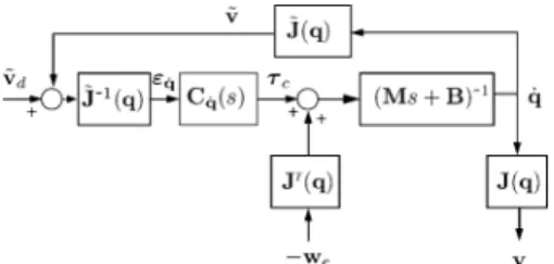
Fig. 4. Force feedback control scheme for KDMs. The scheme depicts both the proposed approaches, depending on the value ofS (S is either a rank n selection matrix, or simply the identity).
where it appears that the force control problem has been artifi-cially squared: when the reduced robot jacobian matrix is not singular, the equilibrium configuration leads for the reduced wrench , that contains the selected force components, to be equal to specified components in .
With the second approach, the joint equilibrium condition leads to
(31) This means that the end-effector wrench error is not necessarily zero, but belongs to the null space of . In other words, an equilibrium is obtained between a virtual (rather than desired) wrench and the external wrench .
C. Passivity Analysis of the Two Proposed Force Control Approaches
Fig. 4 depicts the control scheme for the two proposed ap-proaches. The corresponding linearized output admittance of the system with its controller is given by
(32) where either or is a selection matrix of rank .
Note that here, the admittance under consideration is , where no particular structure is assumed for . This choice is made because no particular contact geometry is assumed. Get-ting back to the comanipulation example depicted in Fig. 1, it is clear that external wrenches can be applied in any directions by the operators. However, if a particular application was con-sidered with a known contact geometry and a perfect contact model, in such a way that some of the wrench components can be supposed to be always null, one could design appropriately the selection matrix so that at any time and check for the passivity of
which, thanks to Assumption 1, is equivalent to the passivity of defined in (20). However, again, this study focuses on the passivity of the closed loop system when submitted to an arbitrary external wrench, so that the passivity of the admittance
given in (32) is under consideration.
Proposition 3: Under Assumption 1, the admittance
given in (32) is passive if, and only if:
C1) ;
C2) the conditions (21) are verified (i.e., the corresponding direct joint torque controller is passive).
The proof of this proposition is given in the Appendix.
Conditions C1) and C2) are completely independent. Condi-tion C2) applies to the control gains of the joint compensator with respect to the robot inertia, while condition C1) concerns the robot kinematics and the selection matrix.
Note that condition C1) applies to the linearized kinematics around a given configuration . However, if we want this condition to be verified for any configuration , it is then necessary and sufficient that
Condition C1) is obviously satisfied with the second approach, i.e., when . Moreover, with the first approach, when , Condition (C1) may also be satisfied, but only for a specific class of robots, and an appropriate selection.
Namely, Condition C1) will be satisfied, if and only if the following.
• The considered robot has a particular design that, by the mean of a bright choice of the jacobian reference frame and expression point, allows for the expression of the jacobian matrix with null lines.
• The zeros of are chosen to match the null lines of the
computed .
In most cases, does not have zero lines in all the workspace, so that one cannot find a selection matrix of rank providing passivity. Therefore, most frequently, one shall use 6 components of the wrench to provide passive force control of an -joint kinematically defective manipulator by projecting the wrench error into the joint space according to (27).
Remarkably, Condition C1) refer only to the kinematic prop-erties of the robot and the selection matrix. This justifies a
pos-teriori the use of the term kinematic instability to qualify the
problem studied in this paper.
Indeed, the experimental results provided in Section VII will show that for surgical comanipulation applications where the contact geometry is not known, if Condition (C1) is not satis-fied, the selection of the wrench components may lead to a lack of passivity which in turn may induce instability. On the other hand, by formulating the problem in the joint space, i.e., when , Condition C1) is always satisfied and thus the stability of the controller is unconditionally guaranteed.
VI. DAMPINGCONTROL OFKDMS
A. Damping Control of Conventional Manipulators
Damping control is a particular implementation of impedance control, that is aimed at controlling not only the nominal ve-locity of a robot, but also the laws that govern the deviation from the nominal velocity generated by external forces.
Considering a conventional manipulator with 6 DoFs, damping control allows for the specification of both a reference velocity , which is the desired velocity for the robot when it does not experience any contact with its environment, and a damping matrix , such that
(33) A physical interpretation of this behavior consists in replacing the robot by an equivalent virtual damper attached to the
end-Fig. 5. Equivalent desired behavior of a conventional (6 DoFs) manipulator under damping control. Here, the 6 DoFs damperD is materialized by an equiv-alent set of individual 1 DoF dampers.
effector, whose reference velocity can be controlled indepen-dently (see Fig. 5).
Two different types of controllers can provide this behavior. The first type uses at the lowest level a force/torque controller, which allows for specifying a desired wrench . An external velocity loop is then added that computes in function of the velocity error by
(34) The second type of damping controller exploits at the lowest level a velocity loop, which is fed with a desired velocity . An external force/torque loop is then added for the computation of this desired velocity in function of the reference velocity and the measured external wrench by
(35) It can be noticed that both controllers described by (34) and (35) provide only an approximation of the desired behavior given by (33). Namely, the desired behavior is achieved if the inner loop is fast and precise enough to provide an output that is permanently equal to the desired input (i.e.,
and , respectively). Clearly, this is valid only within a limited bandwidth, that should be large enough with respect to the overall system bandwidth. Therefore, since a higher bandwidth can be obtained for the inner force control loop than for the inner velocity control loop, the first implementation should be preferred. However, in some particular cases, one has no choice but using the second implementation, e.g., when the robot control hardware includes velocity loops that cannot be removed.
In any cases, when considering a kinematically defective ma-nipulator, difficulties occur with both implementations. Indeed, only a reduced -component velocity vector can be speci-fied. On the other hand, as emphasized in the previous section, reducing the force measurement through a selection matrix may lead to kinematic stability problems. Therefore, the problem of mapping 6 components of a wrench into components of a ve-locity should be addressed carefully. This is done in the next two sections, by considering both the inner force loop and the inner velocity loop implementations.
B. Damping Control of KDMs With an Inner Force/Torque Loop
Assume that a KDM is equipped with a force/torque loop, that allows for the specification of a desired wrench , as detailed
Fig. 6. Damping control for kinematically defective manipulators with a pas-sive inner force/torque loop.
in Section V. Here, obviously, a passive formulation shall be chosen, with a non reduced wrench measurement.
On the other hand, due to the kinematic constraint, one cannot specify for a 6-component reference velocity . Rather, a re-duced reference velocity , with components, can be speci-fied. The external velocity loop shall compute an error between this reduced reference velocity and the reduced velocity
(36) and compute a desired wrench for the inner loop by
(37) where is a matrix which elements are homogeneous to damping coefficients. The corresponding control scheme is given in Fig. 6.
In order to evaluate what possible choices can be made for , a passivity analysis is proposed in the next section.
Here, the output passivity is under study, i.e., passivity be-tween external wrenches and velocities. Therefore, the output admittance is considered, while a null reference ve-locity is assumed, which leads to
(38)
where , is the closed-loop
admit-tance of the direct joint torque controlled robot as defined in (20).
Proposition 4: Under Assumption 1, the admittance
defined in (38) is passive if, sufficiently it follows:
1) is positive real;
2) is positive definite.
This proposition is proven in the Appendix.
Note that Condition 1) is simply equivalent to the passivity of the inner loop. Moreover, a first possible choice for in order to respect Condition 2) is to consider the desired behavior given in (33), and to add the kinematic constraint provided by the robot. Namely, since one has
(39) Equation (33) can be rewritten as
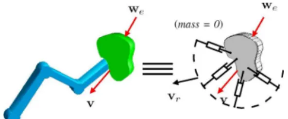
Fig. 7. Equivalent desired behavior of a kinematically defective ma-nipulator under damping control with an inner force loop, when setting D = D J(q) ~J(q) . Here, the 6 DoFs damper D is materialized by an equivalent set of individual 1 DoF dampers.
In this case
(41) so that the positive definiteness of is sufficient to guarantee the system passivity. In order to physically interpret the behavior of the system with this choice for , let us assume that, within a limited bandwidth, the inner loop provides a null error, that is
One obtains for the closed-loop behavior
(42)
where here, is the velocity error of the
robot end-effector when it experiences a reduced velocity error . In other words, at any time, the external wrenches equili-brate with the wrench produced by a virtual damper attached to the end-effector, while the end-effector is attached to virtual unactuated mechanism, that has no inertia and reproduces the kinematic chain of the robot. The equivalent physical system is represented in Fig. 7. Notice that a 6-D virtual damper can be specified, although, obviously, it cannot be fully realized by the robot due to a lack of DoFs.
Note that another possible choice for consists in setting (43) with positive definite. Indeed, in this case, one has
(44) which is positive definite thanks to Assumption 1. The closed-loop behavior becomes (at low enough frequencies)
(45) which corresponds to the behavior obtained in (42) and the equivalent mechanical system depicted in Fig. 7, with the generalized damper that specifies null damping coefficients for the unselected directions.
C. Damping Control of KDMs With an Inner Velocity Loop
In this section, it is assumed that a KDM is provided with a passive velocity controller, such as the one depicted in Fig. 2.
Fig. 8. Damping control for kinematically defective manipulators with a pas-sive inner velocity loop.
The input of this low level controller is a reduced velocity . An external force/torque loop is to be designed, which writes, by analogy to (35)
(46) where is a matrix of gains which elements are homogeneous to the inverse of a damping coefficient. The cor-responding control scheme is given in Fig. 8.
Again, in order to evaluate what possible choices can be made for , let us evaluate the passivity of the output port, that is the positive realness of the following admittance:
(47) where is the admittance of the velocity controlled robot at the joint level, defined in (18).
Proposition 5: Under Assumption 1, the admittance defined in (47) is passive if and only if
such that rank and
(48) and, setting , the following conditions are veri-fied:
is PSD is PSD
(49)
This proposition is proven in the Appendix.
One can note that selecting an appropriate matrix can be done by choosing a PSD matrix , that can be viewed as a matrix of gains which elements are homogeneous to the inverse of joint damping coefficients. Also, Condition (48) imposes that all the 6 wrench components must be measured in order to guar-antee the system passivity, unless, of course, thanks to a partic-ular kinematic design, columns of are null (in this case, one can find of rank such that ). This is consistent with the result obtained for force feedback control. Condition (49-a) is easy to satisfy as it only applies to con-trol gains and leaves a wide possible choice for , and , which includes any positive diagonal matrices. Moreover, Con-dition (49-b) could be satisfied with choices for and/or that depend on , such as, e.g., and . If, for
Fig. 9. Equivalent desired behavior of a kinematically defective manipulator under damping control with an inner velocity loop. For a general robot and con-stant control gains, the passivity constraint only allows for the specification of a joint damping behavior.
simplicity, is chosen to be constant and diagonal, Condition (49-b) can still be statisfied if
with (50)
In this case, it can be straightforwardly verified that Conditions (49-a) to (49-e) are satisfied for any choice of positive diagonal matrices , , and .
In other words, the choice given in (50) is a simple and prac-tical way to provide passivity. With this choice, the closed loop behavior is given, within the limited bandwidth where one can
assume , by
(51) or
(52) An equivalent mechanical system, depicted in Fig. 9, consists in a kinematic chain identical to the robot, each joint being equipped with a damper exhibiting a damping coefficient equal
to .
VII. FORCECONTROLEXPERIMENTALRESULTS ON A
MINIMALLYINVASIVESURGICALROBOT
In this section, we compare the practical behavior of the force control scheme depicted in Fig. 4, with two different choices for the matrix . To do so, a minimally invasive surgical robot interacting with an unknown environment is used.
A. Experimental Setup
The robot (French acronym for compact manipulator
for endoscopic surgery) is a KDM specially suited for minimally
invasive robotic surgery applications [31], [32]. With joints and a spherical structure, this robot provides 4 degrees of freedom at the instrument tip, which evolves in .
More precisely, the robot consists of two parts, as shown in Fig. 10. The lower part is a compact spherical 2 DoFs mech-anism ( and ) which joint axes coincide with the trocar center. This provides an invariant center at the fulcrum point. The upper part of the robot (see Fig. 11) is mounted on the trocar. It provides the two remaining DoFs: the rotation about
Fig. 10. Picture ofMC E with joint parameters. This robot can comanipu-late an instrument with a surgeon, and measures wrenches applied either by the surgeon, or at the instrument tip.
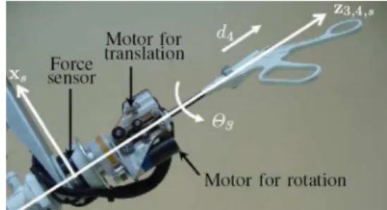
Fig. 11. Upper part of theMC E robot, which realizes rotation and translation of the instrument.
the instrument axis and translation along the instrument
axis .
The Fig. 10 shows, the robot fixed base frame located at , and the end-effector frame located at the instrument tip ”.
Apart from its compactness, the main feature of this robot is that it offers a new possibility of force measurement in mini-mally invasive surgery. Namely, can measure the distal organ-instrument interaction with a 6-axis force-torque sensor placed outside the patient (thus subject to much less steriliza-tion constraints). Remarkably, due to the special mounting of the force sensor, neither the friction between the instrument and the trocar nor the wrench between the trocar and the patient’s skin influence these measurements.
With the same sensor it is also possible to measure forces due to surgeon-instrument interaction. Therefore, this robot is suited for comanipulation tasks, i.e., the robot and the surgeon can si-multaneously manipulate the instrument (see [32] for details).
B. Experimental Results With Force Control
A set of experiments was conducted with for the eval-uation of the practical behavior of the force control scheme de-picted in Fig. 4, with two different choices for the matrix . More precisely, the objective for these experiments is to eval-uate the system behavior when using a passive controller, noted Controller , and a non passive controller, noted Controller . During these experiments, the robot interacts with an un-known environment illustrated here by two different contact points: one at the instrument tip and the other near the in-strument handle .
For practical reasons (flexion and backlash introduced in the overall system), due to a lack of performance of the prototype’s third joint transmission, the joint was intentionally frozen. In the following, only joints ( , , and ) are used without any consequence during the experiments.
In a first tuning stage, all the gain matrices ( , , and ) were chosen to be diagonal and constant over the workspace. This gains values
were chosen in such a way that the conditions given in (21) are verified. Consequently, the passivity of the system only depends on the selection matrix . During all the experiments, the Jaco-bian matrix of the robot is expressed in the fixed robot base frame , at the instrument tip . Therefore, from the force and moment initially measured in the sensor frame, one calculates the force and moment at point and project them into the robot base frame , which is done thanks to standard robot geomet-rical model and exploits the measurement of the robot position, as detailed in [32].
In a first experiment (Experiment 1), the instrument is rigidly attached to a fixed environment near its tip . This illustrates the situation when the instrument contacts the patient organ. For this experiment, two controllers are evaluated as follows.
• Controller does not use any selection: . There-fore, theoretically, it is passive.
• Controller uses a component selection aimed at servoing the force at the instrument tip: . According to the theoretical study provided in this paper, as the con-dition is not verified, Controller is not passive. In order to present comparable results for the two controller,
the desired wrench is
speci-fied for both the controllers, with triangular signals components varying between 1 and 3 N (for and ), and between
and (for ).
The experimental results are first plotted in the joint space, in Fig. 12. In this experience, controller runs from to 2.4 s. At 2.4 s, Controller is switched off while Controller is switched on. In these plots, the desired torque
was computed by for Controller and
for Controller . Due to the choice for , one has so that these desired torques are identical.
It can be observed that both the controller behave in a very similar way. In particular, although not passive, Controller is stable. This is due to the fact that a small clamping device was used near point to attach the instrument to the environment. Therefore, the moments at point are small. As a result, in practice, the wrench exerted by the instrument on the environ-ment, expressed at point , verifies . As noticed in Section V-B, Controller responds passively to wrenches that verify . Experiment 1 is thus an experimental ev-idence that, when this condition is approximately verified, the stability is maintained.
Fig. 12. Experiment 1: Results at the joint level.
Fig. 13. Experiment 1: Results at the end-effector level.
Next, end-effector forces and moments measured during the same experiment are plotted in Fig. 13. At the end-effector level, a difference can be observed between the two controllers. With Controller (see Fig. 13, 2.4 s), the forces only ap-proximately reach their “desired value”. This shall not be con-sidered as a lack of performance. Indeed, one should keep in
Fig. 14. Experiment 2: Results at the joint level. The system is stable from t = 0 to t = 0.6 s, when Controller A is used. At t = 0.6 s, Controller B is switched on which leads to instability.
mind that with this control formulation, represents a virtual
wrench and not a desired wrench. Namely, should balance the effective wrench through
By no way, we are trying to obtain that some of the components of equal the corresponding components of .
On the contrary, for Controller (see Fig. 13, 2.4 s 4.5 s), the null torque error imposes that the three measured force components are equal to the three desired force compo-nents. Meanwhile, as observed in Fig. 13(d), the moment com-ponents at point are rather small. For this reason, we have , which explains why the controller, although not passive, is stable for this particular interaction.
In a second experiment (Experiment 2), the clamp was re-moved from and attached at point near the handle of the instrument (see Fig. 10). This illustrates the situation when the surgeon grasps the instrument in a comanipulation mode. On the other hand, the two controllers are kept unchanged. In this configuration, Controller lead to instability, as illustrated in Fig. 14. In this plot, from to 0.6 s, Controller is running, with a zero desired wrench. It can be observed that the joint torques stably remain null. At 0.6 s, one switches from Controller to Controller . It can be observed that the mea-sured force rapidly diverges.4Clearly, with a clamp placed at point , the equality is not verified, even approxi-mately. In this case, the lack of passivity induces instability.
4In fact, the measured force stabilizes at a given value after approximately
150 ms, but this phenomena is only the consequence of a saturation value that was imposed to the motors current in order to preserve the robot safety.
Fig. 15. Experiment 3: Results at the joint level.
Fig. 16. Experiment 3: Results at the end-effector level.
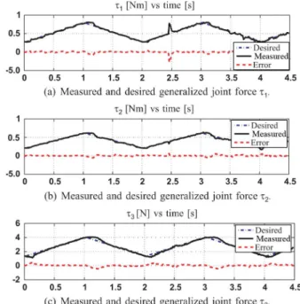
Finally, Figs. 15 and 16 show the results for a third ex-periment, where Controller is used while the instrument is clamped at point , with consisting of triangular signals for force components and null moment at point .
The robustness of Controller is emphasized, as the joint torques are stably servoed to their desired values. Moreover, Fig. 16 shows that the components of the virtual force and the components of the actual force are completely different. Namely, they are almost opposite. This is explained by the fact that the virtual wrench is a force applied at point , that bal-ances the actual wrench , which is applied at point , on the opposite side from the fulcrum point.
VIII. OVERVIEW ANDCONCLUSION
This paper has considered the problem of force control for kinematically defective manipulators, in a context where arbi-trary external wrenches can be applied to the end-effector.
Although, intuitively, one could have thought that only components of force or torque are enough for the control of joint robots, both the theoretical analysis and the experimental results have shown that this cannot be achieved in general. Namely, we have established the necessary and sufficient condition for a passive, thus kinematically stable, component selection. This condition, given by , is satisfied only if the considered robot has a particular design that, thanks to a judicious choice of the jacobian reference frame and expression point, allows for generating only non null and controllable velocity components.
However, from a practical point of view, it is most likely that for a non particular robot kinematics, such a reference frame and expression points cannot be found. It is thus difficult to satisfy
the condition for .
Alternatively, by formulating the problem in the joint space, we have proposed a passive force control scheme that does not use component selection and applies to any KDM. Indeed, for KDM robots, one shall use all the 6 wrench component (i.e., ), which leads to a standard Jacobian transpose control. An important feature of this approach is that the stability is guar-anteed but the equality between the desired and the external wrench cannot be obtained: the wrench is not anymore a
de-sired value for the measured wrench but rather a virtual wrench
which the actual wrench shall balance.
This paper also provided a comprehensive way of specifying a damping behavior for a KDM. If a passive inner force loop is used, a generalized 6 DoFs damper can be specified and at-tached to the kinematic chain of the robot that represents the constraint. On the contrary, the only possible passive formula-tion of a damping behavior when using an inner velocity loop is to use constant joint dampers. These propositions shall be ex-perimentally evaluated.
Within the development of a teleoperated system for mini-mally invasive surgery, that will exploit as a slave arm and a conventional haptic device as a master arm, we are now extending these results to a passive formulation of the telema-nipulation for KDMs.
APPENDIX
Proof of Proposition 1: The positive realness of de-fined in (18) is equivalent to the positive realness of its inverse
(53) Finally, the following can be verified.
1) The only pole of , which is , is not strictly in the right hand plane.
2) The residue matrix ,
associ-ated to pole is hermitian, positive definite since is designed to be symmetric, positive definite.
The residue matrix
as-sociated to the pole at the infinity is Hermitian, positive definite.
3) One can straightforwardly show that
(54) which is positive definite since both and are positive definite.
Therefore, according to property 1, is positive real and, overall, the output port of the closed loop system is passive.
Proof of Proposition 2: Property 1 can be used to verify
the positive realness of .
1) has one pole that verifies and
poles that are the solutions of and are all strictly negative.
2) At the finite pole , the residue of writes
shall be Hermitian, which leads to the necessary Con-dition (21-a).
3) In order to verify the third condition, one has to compute and verify its positive semidefiniteness.
One has
where . Moreover, the positive semidefiniteness of is equivalent to the positive semidefiniteness of
that is
(55) Developing this expression, one gets
(56) Decomposing into its real and imaginary parts, one gets , where , , and are constant real matrices defined by
(57)
The system is passive only if is PSD for any where it is non singular. This condition writes:
Therefore, the necessary and sufficient conditions for the posi-tive semidefiniteness of are
and: and:
is PSD
Next, recalling that , , , , and are
all symmetric, and remarking that is symmetric as well, the necessary and sufficient conditions for the positive semidef-initeness of are the ones given in Conditions (21-b) to (21-d).
Proof of Proposition 3: In order to study the passivity of
, let us first consider the third condition of property 1. One shall study the sign of for any , with
Consider the eigen decomposition of , which, thanks to Assumption 1, is of rank . Let be the matrix grouping the eigenvectors of associated with the strictly positive eigenvalues of , and be the matrix grouping the eigenvectors of associated with the null eigenvalues of . One has,
(59) where lies in the nullspace of . Therefore, one has,
(60) Let us first assume that the matrix is not null. In this case, it is always possible to find such that
.
Furthermore, as the columns of span the range space of , the matrix is obviously of full rank . Therefore,
such that the matrix is of full rank .
To summarize, it is always possible to find and such that
(61) with . With this choice for and , one obtains, com-bining (61) with (60)
which is strictly negative.
In conclusion, a necessary condition for the positive
semidefi-niteness of is that . Recalling
that the columns of span the kernel of , one has
(62) In other words
(63) Moreover, from Assumption 1, we know that is of full rank . Therefore, the matrix , which has lines equal to the lines of and lines of zeroes, is also of rank
. Therefore, both and are of dimension
, and
(64) On the other hand, trivially
(65)
Since both and are of dimension , (65)
leads to
(66) Finally, from (64) and (66), one gets
(67) Since is spanned by the set of vectors of the canon-ical base of corresponding to the selected directions, it fol-lows that the same base spans the range space of . Thus, the vectors of have a component which is null along any of the non-selected directions. In other words, the lines of corresponding to the non selected directions are null, which leads to
or, equivalently: (68)
This condition is necessary for the system passivity. Supposing that this condition is verified, the output admittance , re-duces to
(69) Thanks to Assumption 1, , so that the positive realness is equivalent to the positive realness of [i.e., the joint compensator shall respect the conditions given in (21)].
In summary, the positive realness of is obtained if, and only if, and is positive real.
Proof of Proposition 4: Since is of full rank , the posi-tive realness of the admittance given in (38) is equivalent to the positive realness of
Fig. 17. Equivalent block diagram for the passivity analysis of inner force based damping control of KDMs.
This transfer can be viewed as the system depicted in Fig. 17. Therefore, it is positive real if, sufficiently [28]:
1) is positive real;
2) and is positive definite.
In other words, given an inner passive force loop, it is suf-ficient that satisfies the positive definiteness of in order to guarantee the passivity of the overall system.
Proof of Proposition 5: A first necessary condition for the
admittance given in (47) to be positive real is that has the same kernel as . Indeed, in order to check for the third condition of property 1, one shall study the sign of
Using, for , the decomposition given in (59), and setting
with chosen such that is
invertible and chosen such that leads to
(70) which is strictly negative. Such a choice is always possible un-less has the same kernel as .
Therefore, there must exist a full rank matrix such that
(71) In this case, one has, from (47)
(72) Thanks to Assumption 1, the positive realness of the admittance
is then equivalent to the positive realness of
(73) In turn, it is equivalent to study the passivity of the impedance
(74) where, for shortness, one has set .
Invoking property 1, one can check for the following three conditions.
1) Poles of shall be in the right-hand half plane. Re-placing by its expression from (18) and by its expression from (17) one gets
where . The poles of are then the
solutions of
(75) Since their real part shall be non positive, one gets Condi-tion (49-a).
2) has no pure imaginary poles. 3) The last necessary condition is that
shall be PSD. Multiplying on the left by
and on the right by , it is equivalent to check for the positive semidefiniteness of
(76) Similarly to the analysis provided for , in the proof of proposition 2, the necessary and sufficient conditions for the positive semidefiniteness of where it is not singular are as follows:
1) ;
2) ;
3) is PSD;
4) is PSD.
This straightforwardly leads to Conditions (49-b) to (49-e) by using the symmetry of , , and .
REFERENCES
[1] N. Zemiti, G. Morel, A. Micaelli, B. Cagneau, and D. Bellot, “A pas-sive formulation of force control for kinematically constrained manip-ulators,” in Proc. IEEE Int. Conf. Robot. Autom., Orlando, FL, May 2006, pp. 2238–2243.
[2] D. Prattichizzo and A. Bicchi, “Specifying consistent control goals for kinematically defective manipulation systems,” in Proc. IEEE
Int. Conf. Robot. Autom., Minneapolis, MN, Apr. 1996, vol. 1, pp.
3532–3537.
[3] D. Prattichizzo and A. Bicchi, “Consistent task specification for manip-ulation systems with general kinematics,” ASME J. Dyn. Syst., Meas.,
Control, vol. 119, pp. 760–767, 1997.
[4] G. Guthart and J. Salisbury, “The intuitive telesurgery system: Overview and application,” in Proc. IEEE Int. Conf. Robot. Autom., San Francisco, CA, Apr. 2000, vol. 1, pp. 618–621.
[5] P. Berkelman, E. Boidard, P. Cinquin, and J. Troccaz, “LER: The light endoscope robot,” in Proc. IEEE/RSJ Int. Conf. Intell. Robots Syst., Las Vegas, NV, Oct. 2003, vol. 3, pp. 2835–2840.
[6] N. Zemiti, T. Ortmaier, and G. Morel, “A new robot for force con-trol in minimally invasive surgery,” in Proc. IEEE/RSJ Int. Conf. Intell.
Robots Syst., Sendai, Japan, Sep. 2004, vol. 4, pp. 3643–3648.
[7] K. L. Doty, C. Melchiorri, and C. Bonivento, “A theory of generalized inverses applied to robotics,” Int. J. Robot. Res., vol. 12, no. 1, pp. 1–19, 1993.
[8] L. Stocco, S. E. Salcudean, and F. Sassani, “On the use of scaling ma-trices for task-specific robot design,” IEEE Trans. Robot. Autom., vol. 15, no. 5, pp. 958–965, Oct. 1999.
[9] E. M. Schwartz, R. Manseur, and K. L. Doty, “Noncommensurate sys-tems in robotics,” Int. J. Robot. Autom., vol. 17, no. 2, pp. 86–92, Mar. 2002.
[10] D. Prattichizzo, P. Mercorelli, A. Bicchi, and A. Vicino, “Noninter-acting force/motion control of defective manipulation systems,” in
Proc. IEEE Int. Conf. Dec. Control, Kobe, Japan, Dec. 1996, vol. 2,
[11] D. Prattichizzo, P. Mercorelli, A. Bicchi, and A. Vicino, “On the geo-metric control of internal forces in power grasps,” in Proc. IEEE Int.
Conf. Dec. Control, San Diego, CA, Dec. 1997, vol. 2, pp. 1942–1947.
[12] C. H. An and J. M. Hollerbach, “Kinematic stability issues in force control of manipulators,” in Proc. IEEE Int. Conf. Robot. Autom., Apr. 1987, vol. 4, pp. 897–903.
[13] H. Zhang, “Kinematic stability of robot manipulators under force con-trol,” in Proc. IEEE Int. Conf. Robot. Autom., Scottsdale, AZ, 1989, vol. 1, pp. 80–85.
[14] M. Raibert and J. Craig, “Hybrid position/force control of manipula-tors,” ASME J. Dyn. Syst., Meas., Control, vol. 102, pp. 126–133, 1981. [15] B.-J. Yi, I. D. Walker, D. Tesar, and R. A. Freeman, “Geometric sta-bility in force control,” in Proc. IEEE Int. Conf. Robot. Autom., Sacra-mento, CA, Apr. 1991, pp. 281–286.
[16] T.-S. Chung, “An inherent stability problem in cartesian compliance and an alternative structure of compliance control,” IEEE Trans. Robot.
Autom., vol. 7, no. 1, pp. 21–30, Feb. 1991.
[17] H. Lipkin and J. Duffy, “Hybrid twist and wrench control for robotic manipulator,” ASME J. Mechanisms, Transmissions, Autom. Des., vol. 110, pp. 138–144, Jun. 1988.
[18] A. Abbati-Marescotti, C. Bonivento, and C. Melchiorri, “On the invari-ance of the hybrid position/force control,” J. Intell. Robot. Syst., vol. 3, no. 3, pp. 233–250, 1990.
[19] W. D. Fisher and M. S. Mujtaba, “Hybrid position/force control: A correct formulation,” Int. J. Robot. Res., vol. 11, no. 4, pp. 299–311, 1992.
[20] L. D. Joly, “Commande hybride position/force pour la téléopération: une approche basée sur des analogies mécaniques,” Ph.D. dissertation, Université de Paris 6, Paris, France, 1997.
[21] Y. Shen and K. Huper, “A joint space formulation for compliant motion control of robot manipulators,” in Proc. IEEE Int. Conf. Mechatron.
Autom., Niagara Falls, Canada, Jul. 2005, vol. 1, pp. 362–369.
[22] B. Siciliano, G. Giralt and G. Hirzinger, Eds., “Parallel force/position control of robot manipulators,” in Proc. 7th Int. Symp. Robot. Res., 1996, pp. 78–89.
[23] B. Siciliano and L. Villani, Robot Force Control. Norwell, MA: Kluwer, 1999, vol. 540, International Series in Engineering and Computer Science.
[24] R. M. Murray, Z. Li, and S. S. Sastry, A Mathematical Introduction to
Robotic Manipulation. Boca Raton, FL: CRC Press, 1994. [25] L. Sciavicco and B. Siciliano, “Modelling and control of robot
ma-nipulators,” in Advanced Textbooks in Control and Signal Processing
Series, 2nd ed. New York: Springer Verlag, 2000.
[26] B. Siciliano and L. Villani, “A passivity-based approach to force regu-lation and motion control of robot manipulators,” Automatica (J. IFAC), vol. 32, no. 3, pp. 443–447, Mar. 1996.
[27] T. J. Tarn, N. Xi, and B. K. Ghosh, Control in Robotics and
Automa-tion Sensor Based IntegraAutoma-tion, J. D. Irwin, Ed. New York: Academic, 1999.
[28] H. K. Khalil, Nonlinear Systems, P. Education, Ed., 3rd ed. Engle-wood Cliffs, NJ: Prentice-Hall, 2002.
[29] B. D. Anderson and S. Vongpanitlerd, Network Analysis and Synthesis
-A Modern Systems Theory Approach. Englewood Cliffs, NJ: Pren-tice-Hall, 1973.
[30] D. Williams and O. Khatib, “Improved force control for conventional arms using wrist-based torque feedback,” in Proc. Int. Symp.
Experi-mental Robot., Stanford, CA, Jun. 1995, pp. 516–525.
[31] N. Zemiti, T. Ortmaier, M. Vitrani, and G. Morel, “A force controlled laparoscopic surgical robot without distal force sensing,” in Proc. Int.
Symp. Experimental Robot., Singapore, Jun. 2004, pp. 153–163.
[32] N. Zemiti, G. Morel, T. Ortmaier, and N. Bonnet, “Mechatronic design of a new robot for force control in minimally invasive surgery,” IEEE/
ASME Trans. Mechatron., vol. 12, no. 2, pp. 143–153, Apr. 2007.
Nabil Zemiti received the B.Sc. degree in electronics
engineering from the University of Science of Al-giers (USTHB), Algeria, in 2001 and the M.Sc. de-gree in virtual reality and complex systems from the University of Versailles (UVSQ), Versailles, France, in 2002, and the Ph.D. degree in robotics from the University of Pierre & Marie Curie—Paris 6, Paris, France, in 2005.
He is currently an Assistant Professor with the Robotics Department, LIRMM Laboratory, Univer-sity of Montpellier II, Montpellier, France. From
October 2002 until August 2006, he was a Researcher with the Robotics Laboratory of Paris, University of Paris 6, where he was working on the force-feedback control of medical robots. From September 2006 until August 2008, he was a Post-Doctoral fellow at the TIMC/IMAG Laboratory, Grenoble, France, where he was working on computer assisted medical interventions and sensor-based control for robotic manipulators.
Guillaume Morel (M’97) received the Ph.D. degree
from the University of Pierre & Marie Curie—Paris 6, Paris, France, in 1994.
He is now a Professor of Mechanical Engineering with the University Pierre & Marie Curie. He was a Postdoctoral Research Assistant with the Depart-ment of Mechanical Engineering, Massachusetts In-stitute of Technology, Cambridge, in 1995–1996, and an Associate Professor with the University of Stras-bourg, France, from 1997–2000. After a year spent as a Research Scientist for the French company of elec-tricity (EDF), he joined the Laboratoire de Robotique de Paris (now Institute for Robotics and Intelligent Systems), Paris, France. His research has concerned the sensor-based control of robots, with a particular focus on force-feedback con-trol and visual servoing. Application of these techniques for medical robotics (surgery, rehab) is now the main area of his research.
Alain Micaelli was born in Ajaccio, France, in 1956.
He received the Engineer and the Ph.D. degrees in automatic control and signal processing from the Ecole Nationale Supérieure des Télécommu-nications, Paris, France,and from the University of Paris-Sud, France, in 1979 and 1982, respectively.
He joined the Robotics Unit of the French Atomic Energy Commission (CEA) in 1982 and has been in-volved in several national and international projects. He is currently a Research Director in the field of automatic control. His research interests include the control of manipulators, telemanipulators, mobile robots, virtual reality, and more specifically virtual manikin.
Barthélemy Cagneau received the M.S. and Ph.D.
degrees in mechanical engineering from the Univer-sity of Pierre & Marie Curie–Paris 6, Paris, France, in 2005 and 2008, respectively.
He is now working as a Post-Doctoral Research Assistant with the Institut des Systèmes Intelligents et de Robotique (Paris 6), Paris, France. His research interests include force control, adaptive control, and robust bilateral couplings for micro robotics.
Delphine Bellot received the graduate degree in
electrical engineering and automation from Ecole Nationale Supérieure d’Electrotechnique, d’Elec-tronique, d’Informatique, d’Hydraulique et des Télécommunications (E.N.S.E.E.I.H.T.), Toulouse, France, in 1999 and the Ph.D. degree in automa-tion/robotics from the University of Toulouse III, Toulouse, France, in 2002. Her Ph.D. dissertation topic was analysis and synthesis of visual servoing control schemes.
Since 2003, she has been an Associate Professor with the Department of Mechanical Engineering, University of Pierre & Marie Curie—Paris 6, Paris, France. She teaches fundamental of solid mechanics, con-trol, estimation and robotics to undergraduate and graduate classes. She is a member of the ISIR (Institut des Systèmes Intelligents et de Robotique) and her research activities focus on force feedback control applied to surgical robotics.