HAL Id: inserm-01851099
https://www.hal.inserm.fr/inserm-01851099
Submitted on 29 Jul 2018
HAL is a multi-disciplinary open access
archive for the deposit and dissemination of
sci-entific research documents, whether they are
pub-lished or not. The documents may come from
teaching and research institutions in France or
abroad, or from public or private research centers.
L’archive ouverte pluridisciplinaire HAL, est
destinée au dépôt et à la diffusion de documents
scientifiques de niveau recherche, publiés ou non,
émanant des établissements d’enseignement et de
recherche français ou étrangers, des laboratoires
publics ou privés.
Prototype Advancement of the Robotic IV Pole:
Preliminary Simulation
Georges Hajj-Moussa, Abbas Sayed-Kassem, Nancy Kozah, Reem Harb,
Mohammad Arnaout, Amira Zaylaa
To cite this version:
Georges Hajj-Moussa, Abbas Sayed-Kassem, Nancy Kozah, Reem Harb, Mohammad Arnaout, et
al.. Prototype Advancement of the Robotic IV Pole: Preliminary Simulation. 2018 International
Conference on Computer and Applications (ICCA). IEEE CONFERENCE NUMBER 43450., Jul
2018, Beirut, Lebanon. �inserm-01851099�
Prototype Advancement of the Robotic IV Pole:
Preliminary Simulation
Georges Hajj-Moussa
1‡, Abbas Sayed-Kassem
1‡, Nancy Kozah
1‡, Reem Harb
2, Mohammad Arnaout
1, Amira J. Zaylaa
∗1,31Department of Biomedical and Electrical Engineering, School of Engineering, Lebanese International University, Lebanon 2Galien Medical Services Company, Lebanon
3Faculty of Public Health-V, Lebanese University, Lebanon ∗Corresponding Author [email protected]
‡The three students worked equally
Abstract—The Intravenous (IV) poles are medical and healthcare facilities utilized to deliver medications to patients over a scheduled time. Existing Intravenous poles are either commercial poles, that are found in the market, or robotic poles, that are still under research. Despite commercial poles hold and deliver medications, they restricted the movement of patients, consumed the nurses’ time and were costly. The robotic poles in research were able to overcome the movement restrictions however, they needed external accessories to maneuver the pole and they carried light weights merely. The aim of our project is to develop a new prototype for solving the shortcomings of both commercial and robotic poles in order to enhance the healthcare service provided to patients. In this paper we provide the simulation of our automated robotic IV pole to offer new technological features. Several cost-effective build up materials were carefully chosen in this prototype. The first step was the simulation of the prototype of the new robotic pole including its different parts and components, using AutoCAD. Simulation results showed five contributions separated according to the function and/or merged according to the prototype. The preliminary results also showed the best qualitative way to fit all the specifications in the robotic system, such as the overall simulated shape, sensors and connections in order to provide the proper functionality of the system. The experimental development will be consider in our future work.
Index Terms—Robotic IV Pole, Automated Prototype, Healthcare Service, Preliminary Simulation, Biomedical Device.
I. INTRODUCTION
Intravenous (IV) pole instruments are slender metallic rods attached to wheeled base and several hooks [1]. The key role of IV poles is to deliver the necessary medications to the patient via an IV injection [2]. The use of such injection is required when the patient is prescribed large amount of medications over a long interval of time [3]. The height between the bag, containing the medication, and the patient’s heart should be 3 ft [4]. According to our thorough review, IV poles could be divided into two main categories, commercial IV poles and research IV poles. Commercial IV poles resulted in many limitations such as the lack of patient’s comfort while dragging the IV pole, the consumption of the nurses’ time, the lack of sensors to alert the nurse about the IV bag status, and its cost [1]. By taking into consideration the cost of commercial IV poles and their lack of technological features, they are
expensive [1]. With the introduction of research IV poles, such as the autonomous IV pole [5], and the robotic IV pole [6][10], some improvements to the commercial designs have occured especially in the IV poles’ movement field. In the autonomous IV pole, the automated motion was related to the attachment of a nylon twine between the patient and the robotic system. While in the robotic IV pole introduced by Sayed-Kassem et al., the automated motion was provided via a joystick controlled by the patient. Despite the enhancement related to the movement of research IV poles, the motion was not fully automated, and the problems were not completely resolved. Adding to that, the robotic IV poles can also be considered somehow costly. By comparing their presented features and their cost, the autonomous IV pole costs around 2000$ [5] and the Robotic IV pole costs around 300$ [6]. A survey done in a medical center in lebanon on different aspects, including the health and financial advantages of robotic IV pole, showed an agreement on the robotic systems by the majority of patients (85%) , nurses (90%) and human resources (80%) [6]. According to what preceded, the aim of our project is to design a new prototype for our biomedical robotic IV pole. We hypothesize that this new prototype enhances the health care service provided to the patients in hospitals and any medical center. The importance of this paper lies behind providing the simulation of the architecture of the prototype and providing a detailed description of the parameters needed to ensure an automated movement, the saline’s volume/flow and the blood leak detection. The remainder of this paper is organized as follows. Section 2 presents the materials and methods. Section 3 presents the simulation results and section 4 provides the overall conclusion.
II. MATERIALS ANDMETHODS
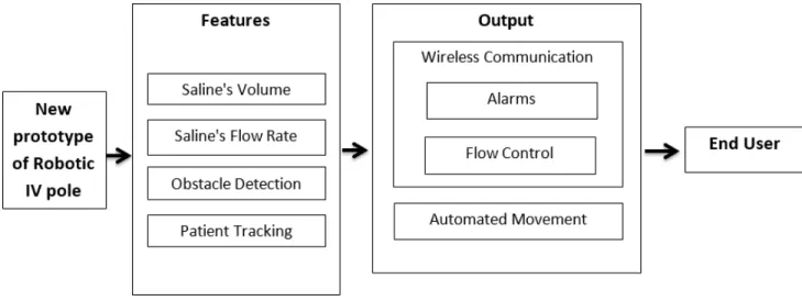
The major part of the advanced Robotic IV Pole prototype is summarized in the block diagram shown in Fig. 1, from the simulated prototype features to be extracted, to the end user. A. Materials
The materials used to simulate the design are the softwares, including the AutoCAD for simulating the new prototype of the Robotic IV pole, the NOOBS OS for programming the
Fig. 1: New Prototype of Robotic IV Pole Block Diagram.
Raspberry Pi [7], and the Arduino IDE for programing the motors [8].
B. Methods
Several methods are used in order to build the simulation of the new prototype of robotic IV pole and provide its features as shown in Fig. 1. The new prototype is divided into different contributions, each of them has a specific function. The contributions of the new prototype are composed of the following:
- Architectural contribution providing the suitable design. - Sensors contributions providing the measurement of
different features related to the saline.
- Patient tracking contribution providing the automated movement.
- Mechanical contribution providing a smooth movement of the robot.
a) Architecture Contribution
For the shape of the new prototype, the implementation is based on the dimensions and materials are chosen based on (Eq.1), (Eq.2), (Eq.3) as follows:
A = 2(1 +√2)a2 (1) where A is the octogonal area in m2and a is the side length in m.
The volume (v) is given by:
v = A × t (2)
Fig. 2: The Simulation of the Different Possible Architectures of the Advanced Robotic Base.
where v is the volume in m3, A is the area in m2 and t is the
thickness in m.
And the mass (m) is given by:
m = ρ × v (3)
where m is the mass in kg, ρ is the density in kg/m3 and v
is the volume in m3. The calculation of the mass leads to the
choice of the appropriate build-up material of the system. b) Sensors Contribution
This contribution provides the ability to measure different parameters regarding the saline’s volume and flow. The electronics used to build the sensors were planned to be simulated in a way to resemble efficient sensors.
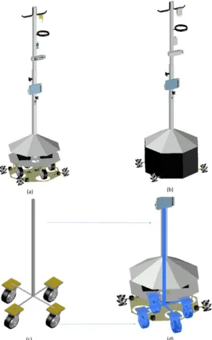
Fig. 3: 3-Dimensional Model of the New Robotic IV Pole. (a) Whole System (Opened). (b) Whole System (Closed). (c) Emergency Casters Outside the System. (d) Emergency Casters Inside the System.
A camera was included in the prototype to track the patient, send the images to the processor, and process images to locate the patient with respect to the pole. The choice of the camera that was planned to be used was based on the maximum distance in which the patient is identifiable. The calculations for this distance was based on the followin equations [9]:
F OV = Rh
N (4)
where F OV is the Field Of View in m, Rh is the horizantal
resolution in pixels and N is the number of pixels per m. d) Mechanical Contribution
A flow control system planned to be placed on the IV pole. The flow system was composed of a stepper motor, a screw and a bolt. Four mecanum wheels, connected to four stepper motors, were needed in order to provide a smooth movement associated with three Degrees Of Freedom (DOF): two translational motions along X and Y-axes, and one rotation about Z-axis. The selection of motors is based on the calculation of the torque given by (Eq.5), this step was made after the weight and the forces were defined.
τ = F × R (5)
where τ is the torque in N.m, F is the force in N and R is radius in m.
The different methods followed in each contribution of the New Robotic IV Pole, showed in details the various values and dimensions leading to realization of the real system as shown in the simulates result.
III. SIMULATIONRESULTS
1) The AutoCAD Simulation: it is architecture contribu-tion which deals with simulating or drawing the geometrical aspects of the parts forming the system. The system was composed of two main parts: the base, and the pole. The base was formed of three parts the floor, the ceiling and the stabilizing part. The latter had a pyramidal shape in order to increase the system’s stability. As for the floor and ceiling parts, they were shaped as squares having a 50 cm side length. During the AutoCAD simulation, the provided surface needs to fit the electronics in it. Thereby, to have a bigger surface while taking into consideration the weight, the best shape was an octagon with a side length of 27.1 cm as shown in Fig. 2. Concerning the dimensions, the robotic base’s height was 52.5 cm, it is the distance between the floor-robot interface and the robotic stand-top of the base interface. The base width
was simulated to be maximum 70.7 cm. Elevating up from the base, the stand, having a length of 216 cm, was the part of the system where the sensors were simulated to be attached. The sensors were designed to be placed in plexiglas boxes, each having specific dimensions, in order to accommodate for the required electronics for each sensor.
The box containing the flow control system had a length of 16.5 cm, a width of 5.5 cm and a height of 5 cm as shown in Fig.4. These measurements were chosen in order to fit the motor, screw and bolt and other electronic components. And the box holding the flow sensor, it will have a 10 cm height, 5.5 cm as width, and 5.5 cm as length in order to hold the ultrasound sensor and the clamps that hold the dripping chamber as shown in Fig.5. Adding to that, emergency casters are placed in the base, used in case of system failure or absence of power. These casters will be attached to a stand having 105 cm of length and inserted inside the main stand.
The 3-D model of the whole system with its different components is shown in Fig. 3. Starting from the bottom, the base is colored with silver, and composed of the floor, ceiling and stabilizing part as shown in Fig. 3 (a). The base simulation result also include the casters, mecanum wheels and several electronics such as, Raspberry Pi, Arduino, motors’ drivers, stepper motors and batteries for the power supply. The walls shown in black in Fig. 3 (b) represent the simulated transparent plexiglas walls connecting the floor, the ceiling and the pyramidal shape. For the remaining parts of the prototype, listed from bottom to top, the camera (green), Lyquid Crystal Display (LCD) screen (light blue), flow control system, flow meter, and the volume detector attached to the hook as shown in Fig. 3 (a). Also a holding ring (black) is placed at the top in order to hold the IV bag in a straight position as shown in Fig. 3 (a). Emergency casters shown in Fig. 3 (c) are placed in the base and their stand is inserted inside the main stand as shown in Fig. 3(d).
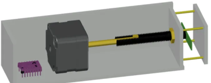
Fig. 4: 3-Dimensional Model of the Flow Control System.
The flow control system is simulated in a plexiglas box as shown in Fig. 4. This system contains the simulated motor’s driver (purple), the stepper motor (gray), the shaft (yellow), the screw (black) and the bolt on the distal tip of the screw, in order to allow the screw’s translation through the bolt, and allow to press on the tube to control the flow.
The flow meter is simulated in a plexiglas box as shown in Fig. 5. The flow meter contains an ultrasound sensor (blue),
and 2 brackets (black) to hold the dripping chamber of the IV tube.
Fig. 5: 3-Dimensional Model of the Flowmeter.
IV. CONCLUSION
The advanced prototype’s simulation of the Robotic IV Pole showed in details the different parts and systems used, in order to achieve the overall functionality of the new prototype of the Robotic IV pole. The simulated results such as the automated movement and the flow control made the upcoming steps clearer and easier. Based on this simulation the implementation and testing steps will be further developed and realized.
REFERENCES [1] S. OT Hulet. (1998-2017) Rehabmart. [Online].
https://www.rehabmart.com/category/iv poles.htm
[2] J. W. Pryor and S. Beach, ”AMBULATORY PATIENT SUPPORT STAND,” 140,603, June 1, 1982.
[3] T. C. Charles and J. George, ”Home care intravenous stand ,” Granting 4905944 A, March 6, 1990.
[4] Masaryk University. [Online].
https://is.muni.cz/do/med/mimsa/12840881/24067852/24067857/5 -Intravenous infusion.pdf
[5] M. Binger, C. Conway, N. Jacobs, E. Whritenor, N. Goddard and C. Pysher, ”Autonomous IV Stand,” in Multidisciplinary Senior Design Conference, New York, 2015, pp. 1-8.
[6] A. Sayed-Kassem, A. Ghandour, L. Hamawy and A.J. Zaylaa. (2017) Cutting-Edge Robotic Intravenous Pole: Preliminary Design and Survey in Academic Medical Center in Lebanon. J Biomed Eng Med Devic vol.2, no. 124. doi: 10.4172/2475-7586.1000124
[7] RASPBERRY PI FOUNDATION. Raspberry Pi. [Online]. https://www.raspberrypi.org/
[8] Arduino. (2017) ARDUINO. [Online]. https://www.arduino.cc/
[9] B. Mesnik, ”Calculating What You Can See With Your IP Camera,” KINTRONICS, p. August, Feb 2017.
[10] A. Ghandour, A. Sayed-Kassem and A. Zaylaa. Cutting Edge Wireless-Based Intravenous Stand Robot. Annual Engineering Exhibition, 2016, May 2016, Beirut, Lebanon.