READ THESE TERMS AND CONDITIONS CAREFULLY BEFORE USING THIS WEBSITE. https://nrc-publications.canada.ca/eng/copyright
Vous avez des questions? Nous pouvons vous aider. Pour communiquer directement avec un auteur, consultez la première page de la revue dans laquelle son article a été publié afin de trouver ses coordonnées. Si vous n’arrivez pas à les repérer, communiquez avec nous à [email protected].
Questions? Contact the NRC Publications Archive team at
[email protected]. If you wish to email the authors directly, please see the first page of the publication for their contact information.
NRC Publications Archive
Archives des publications du CNRC
This publication could be one of several versions: author’s original, accepted manuscript or the publisher’s version. / La version de cette publication peut être l’une des suivantes : la version prépublication de l’auteur, la version acceptée du manuscrit ou la version de l’éditeur.
Access and use of this website and the material on it are subject to the Terms and Conditions set forth at
Pose Determination and Tracking for Autonomous Satellite Capture
Jasiobedski, P.; Greenspan, M.; Roth, Gerhard
https://publications-cnrc.canada.ca/fra/droits
L’accès à ce site Web et l’utilisation de son contenu sont assujettis aux conditions présentées dans le site LISEZ CES CONDITIONS ATTENTIVEMENT AVANT D’UTILISER CE SITE WEB.
NRC Publications Record / Notice d'Archives des publications de CNRC:
https://nrc-publications.canada.ca/eng/view/object/?id=3ead5120-108d-431b-aee4-5ea825583651 https://publications-cnrc.canada.ca/fra/voir/objet/?id=3ead5120-108d-431b-aee4-5ea825583651
National Research Council Canada Institute for Information Technology Conseil national de recherches Canada Institut de technologie de l'information
Pose Determination and Tracking for Autonomous
Satellite Capture *
Jasiobedski, P., Greenspan, M., Roth, G.
June 2001
* published in The 6th International Symposium on Artificial Intelligence, Robotics and Automation in Space. Montréal, Québec, Canada. June 2001. NRC 45869.
Copyright 2001 by
National Research Council of Canada
Permission is granted to quote short excerpts and to reproduce figures and tables from this report, provided that the source of such material is fully acknowledged.
Proceeding of the 6th International Symposium on Artificial Intelligence and Robotics & Automation in Space:
i-SAIRAS 2001, Canadian Space Agency, St-Hubert, Quebec, Canada, June 18-22, 2001.
Pose Determination and Tracking for Autonomous Satellite Capture
Piotr Jasiobedzki
1, Michael Greenspan
2and Gerhard Roth
21
MD Robotics, 9445 Airport Rd., Brampton ON, Canada, L6S 4J3
2
National Research Council of Canada, Bldg. M-50, 1200 Montreal Road, Ottawa ON, Canada, K1A 0R6
[email protected]
Abstract
This paper presents a concept and initial results of testing a vision system for satellite proximity operations. The system uses natural features on the satellite surfaces and does not require any artificial markers or targets for its operation. The system computes motion of unknown objects, and using object models computes their positions and orientations (pose), and tracks them in images sequences. The system processes images from stereo cameras to compute 3D data. Motion of an unknown object is computed using projective vision. Initial pose of the object is acquired using an approach based on Geometric Probing. The pose is tracked using a fast version of an Iterative Closest Point algorithm. Selected modules of the system have been characterised in a representative environment; the other are undergoing systematic sets of experiments.
Keywords
Vision system, satellite proximity operations, motion estimation, pose estimation, tracking
1
Introduction
Satellite servicing includes conducting repairs, upgrading and refuelling spacecraft on-orbit. It offers a potential for extending the life of satellites and reducing the launch and operating costs. Astronauts regularly travel on board of the Shuttle to the Hubble Space Telescope, MIR station and to the International Space Station, and perform similar servicing tasks. The high cost of manned missions, however, limits the servicing to the most expensive spacecraft only. Also, many communication and remote sensing satellites reside on higher, Geo Stationary (GEO) orbits that the shuttle cannot reach. Future space
operations will be more economically executed using unmanned space robotic systems.
The satellite servicing concepts have been discussed for over a decade but only now advanced technologies that are required for such unmanned missions are becoming available. The demand for new satellites and expected lower operating costs provide the motivation. Future satellites will be designed for servicing by autonomous servicer spacecraft and equipped with suitable mechanical interfaces for docking, grasping, berthing, and fluid transfer and electrical interfaces (expansion ports) for installing new computer and sensor hardware [12]. The communication time lag, intermittence and limited bandwidth between the ground and on-orbit segments renders direct teleoperated ground control infeasible. The servicers (chasers) will have to operate with a high degree of autonomy and be able to rendezvous and dock with the serviced satellites (targets) with minimum or no assistance from the ground. One possibility is to employ advanced semi-autonomous robotic interface concepts. An example is supervisory control [5], wherein human operators on the ground segment issue high level directives and sensor-guided systems on the space segment guide the execution. The on-board sensor system should allow the chaser spacecraft to approach the target satellite and identify its position and orientation from an arbitrary direction and manoeuvre the chaser to appropriate docking interface [8, 9].
In this paper we present a computer vision system that can determine and track the relative pose of an observed satellite during proximity operations. The system processes monocular and stereo images, such as are acquired from standard cameras, to compute satellite pose and motion. Initially the vision system estimates motion of a free-floating satellite to determine that it is safe to approach it. The system does not use any prior knowledge or models at this
phase. The vision system then determines an initial estimate of its pose using a 3D surface model of the satellite. Once the approximate pose has been estimated, the vision system tracks the satellite motion during subsequent proximity operations up to the point of mating.
2
Satellite proximity operations
and environment
The autonomous servicer spacecrafts will service satellites located on a variety of orbits extending from the Low Earth Orbit (LEO), 320 km above the earth surface, to Geo-Stationary Orbits (GEO), over 35,000 km.
2.1
Trajectories
The servicers will approach the targets in several steps by reaching predefined waypoints and typically using minimum energy transfers. The initial steps involve placing the chaser on an orbit with the same inclination as the target’s orbit. The target can then be approached along two trajectories: R-Bar and V-Bar [6] (or their combination). R-V-Bar trajectory is oriented along the Earth radius and when a spacecraft is moving along R-Bar the chaser is slowed down as it moves onto higher orbits closer to the target spacecraft. V-Bar approach is executed when the chaser is following the target along the same orbit and approaching it towards its negative velocity face [8]. Space shuttle docks with MIR and ISS occur along R-Bar. ETS-VII, a Japanese experimental docking satellite, performed several docking experiments along both V-Bar and R-Bar trajectories [6, 14].
Future satellite servicing operations may require more flexibility and rendezvous / docking may have to be performed along other approach trajectories. Such trajectories will require more fuel but the maneuevres will be completed faster and with no interaction with the ground control station when passing though pre-defined waypoints [17].
Execution of the final contact phase will depend on the servicer design. If the servicer is equipped with a robotic arm it might be used to capture a free-floating satellite and position it on a specially designed berthing interface on the servicer. Alternatively, the servicer may approach the target and dock directly with it. The shuttle crew uses the first technique to retrieve and service the Hubble telescope, and the second one to dock with the International Space Station.
2.2
Visual environment on orbit
The on-orbit environment’s lack of atmosphere and rich background, that might diffuse sunlight, creates highly contrasting scenes. When the contrast of the scene exceeds the dynamic range of the camera, then part of the image data is lost. On LEO the typical orbital period is from 90 –180 minutes, which includes a complete change of illumination from full sunlight to eclipse. On elliptical and GEO orbits the orbital periods are between 12 and 24 hours; and on sun-synchronous orbits the illumination does not change.
On orbit space environments are often regarded as structured and well known, as all of the objects are man-made, and design documents (CAD models) are available. In order to protect the hardware from the space environment the structures and spacecraft are often covered with loosely attached reflective materials (foil) or featureless thermal blankets. Such surfaces when illuminated with directional sunlight and on-board lights create shadows and specularities that pose difficult problems for imaging cameras and vision systems.
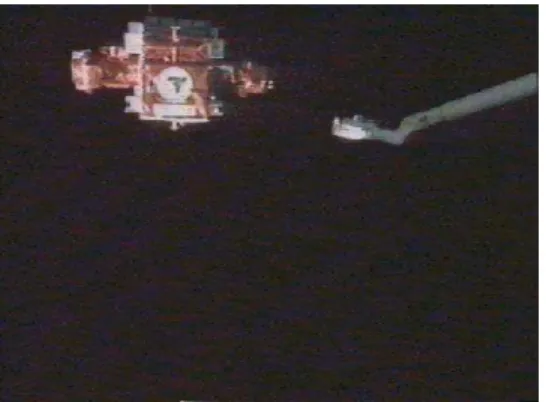
Images obtained during shuttle proximity operations are shown in Figure 1. The Shuttle Remote Manipulator System, the Canadarm, is preparing to grasp a free-floating experimental satellite. The satellite is equipped with a special interface that can be grasped by the end-effector on the arm (see the bottom image in Figure 1). The interface consists of a circular base with a central shaft, three radial support structures and can be seen in the centre of the satellite in the right image. Future satellite servicing missions may use docking interfaces similar in size and shape to this interface.
Figure 1 Grasping of a free-floating satellite with Canadarm. The satellite in the bottom
image has its grappling interface oriented towards the camera
3
Space vision technologies
The vision systems for satellite proximity operations will be used at the range from 100m to contact. This range may be divided into three categories long, medium and short. In the long range (20 – 100m) the vision system should detect and identify the satellite of interest, and determine its bearing and the distance. In the medium range (1-20m) the vision system should identify the satellite motion, distance, and determine its orientation and location of a docking/robotic interface, see Figure 1. At the short range (<2m) the vision system will track the mechanical interface during the final approach and docking/grasping phase.
3.1
Sensors
Data processed by the vision systems may be obtained from a variety of sensors such as video cameras, scanning and non-scanning rangefinders. The video cameras commonly used in current space operations are available at a relatively low cost, have low mass and energy requirements. Their main disadvantage is their dependence on ambient illumination and sensitivity to direct sunlight. Scanning rangefinders [4, 11] are independent of the ambient and less sensitive to sunlight. This comes at a cost/weight/energy requirement of complex scanning mechanisms that may not survive the space environment well. Non-scanning rangefinders [16] offer a potential of low cost/mass/energy and the absence of scanning mechanisms. However, they are still in early development phase.
3.2
Computer vision approaches
The approaches to computer vision in space can be grouped in the following categories:
• Detection of artificial targets (markers) placed on spacecraft
• Detection of individual features (2D and 3D) and matching them with corresponding 3D model features
• Detection of 3D surface data and matching it with 3D models
The current approaches to space vision rely on installing easy to detect and high contrast visual targets on satellites and payloads. Algorithms specifically tuned to these patterns robustly detect their locations in 2D camera images [13, 4]. The satellite pose is estimated by finding a 3D transformation of the observed markers from a default co-ordinate system to the current unknown location, so that the markers will be projected into the image in their observed locations. The internal camera calibration is assumed to be known. This problem is referred to as single camera photogrammetry or external camera calibration. The visual targets can be used only in specific tasks (limited by the distance and viewing angles) requiring the definition of all operations of interest at the design phase and precluding any unexpected tasks. Lack or mis-detection of a target may lead to a vision system failure, as there will be not enough data to compute the reliable camera pose solution. There is certain additional installation and maintenance cost, as the targets must survive the exposure to harsh space environments. The targets are mostly suitable for predefined and short range operations, and when the target satellite/docking interface can be modified. Using natural features and object models will alleviate the limitations of the target based systems. Techniques based on detecting natural features (2D and 3D lines, circles, and regions) and matching them directly with model features do not require installation of any artificial targets, as they rely on existing object geometry and structure. However, reliable detection of features required for matching may be difficult under some conditions encountered on-orbit (illumination, viewing angles and distances). This may lead to ambiguous matching with the 3D model and breakdown of the computed solution. This approach is suitable for short range operations, when the features can be reliably detected and tracked, and when the initial pose is approximately known.
Vision algorithms that will most likely succeed in space will use arbitrary surface features of the object, and do not require establishing and maintaining direct correspondence between small numbers of high level object and model features. This will remove the need to detect specific features under all possible conditions. Presence of shadows, specular reflections and background features are likely to confuse algorithms based on analysis of single 2D images; therefore using 3D data computed from image sequences and/or stereo becomes essential. Such techniques can be used in the medium operational range as any detectable surface peculiarity including shadows and edges will provide 3D data that can be used in 3D model matching. As direct correspondence is not required, different 3D data sets may be detected depending on the instant viewpoint and illumination. Our vision system uses this approach for medium range operations.
Other computer vision methods, such as those based on object appearance that attempt to match the intensity distributions of the model to images, will have difficulty in the presence of unexpected shadows and reflections typical in space environments. Despite their shortcomings, it may be necessary to rely upon these methods for long range operations where 3D data is not available.
4
Vision
system
for
satellite
proximity operations
The vision system described in this paper is intended for the medium range of satellite proximity operations that extends approximately between 2 – 20m. The vision system processes sequences of images acquired from several cameras arranged in a stereo configuration. The sensors are thus passive, contain no moving parts, are of low mass, consume low amounts of energy, and are relatively inexpensive. The algorithms implemented in this system rely on the presence of natural features and do not require any visual targets. Extraction and processing of redundant data provides robustness to partial data loss due to shadows and reflections. Some of the algorithms may use object models. The vision system operates in several modes and is used in three operational modes: Monitoring, Acquisition, and Tracking.
In the monitoring mode the vision system processes sequences of monocular and stereo images to estimate the rotation and distance to the observed satellite. In this phase the system does not require any prior object models. Once the vision system determines that it is safe to approach the observed
satellite then the servicer may draw near to obtain better 3D data from the stereo system and continues the operations.
When in the acquisition mode the vision system processes 3D data computed by the stereo vision sub-system and estimates an approximate pose of the satellite. During this phase the vision system may be also used to confirm identity, configuration and state of the satellite.
Once the initial pose of the satellite is determined then the tracking mode is invoked and provided with this estimate. During tracking the satellite pose and motion is computed with high precision and update rate. Subsequent proximity operations such as fly-around, homing and docking are performed in the tracking mode.
The vision system handles a handover between the modes passing, for example, a pose estimate from the acquisition to tracking mode; and may use the motion estimated in the monitoring mode to correct for the processing delay of the acquisition phase. Failure to determine the initial pose requires repeating the process with occasional updates of the relative motion using the monitoring mode. Failure of the tracking mode causes the vision system to revert to either the monitoring or acquisition mode depending on the distance to the satellite and current chaser operation. The vision system may be re-configured during its operation and operate simultaneously in multiple modes ensuring correct data handover and error recovery.
4.1
Image acquisition and stereo
sub-system
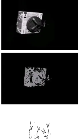
The developed vision system uses a two-camera stereo imaging sub-system. The images are synchronously captured and transferred to a host for processing. Geometrical warping corrects the images for lens distortions and rectifies to simplify the stereo geometry [10]. The images are then processed by one of two stereo algorithms: dense and sparse stereo. The dense stereo algorithm uses normalised correlation and produces densely sampled data of 10k-100k points per scene. The processing time is in the order of seconds and depends on the selected image resolution and selected disparity range. The sparse stereo algorithm extracts edges from both stereo images and computes a sparse representation of the scene (1k of 3D points) in a fraction of second. An example input image of a mock-up used in experiments, dense disparity map and extracted 3D points are shown in Figure 2.
Figure 2 A image of a mockup, dense disparity map and sparse 3D edges
Sequences of stereo images, dense and sparse range data are available to specialised algorithms for further processing. Only data required by currently running algorithms is computed.
4.2
Monitoring
It is sometimes necessary to compute the motion of a satellite without knowing the object type; that is without having a model. This is called model-free satellite motion estimation. When dealing with an isolated object, it is the case that the change in camera position is simply the opposite of the change in the object position. Using this principle we can compute the satellite motion by simply finding the relative camera motion. It has been shown that computing the camera motion is feasible even in an unstructured environment [15]. This is done using only natural features, without any special targets. The combination of random sampling and the linear
algorithms for structure from motion (SFM) are capable of producing very reliable correspondences in an image sequence. From these correspondences it is possible to compute the camera motion assuming that we know the camera calibration a-priori, or we have computed it via an auto-calibration process. There are two different approaches to computing the satellite motion depending on whether the satellite is in the medium range or the far range. For the far range the stereo cameras will not produce accurate depth, so we must rely on a single camera. We have successfully computed both orientation and distance from a single camera using SFM algorithms [15]. However, the process becomes unstable when there is very little translation of the features between views. In this case we plan to compute only the satellite rotation, and not the distance to individual features. Experiments are ongoing with this approach.
Once the satellite reaches the medium range we can achieve reasonably accurate depth from the stereo rig. In this situation we combine the stereo and SFM. At each position of the stereo cameras we get a set of sparse 2D points. Now using only the right images of the sequence we match the 2D pixel locations of these 2D feature points. More precisely, assume we have two stereo camera positions: left1, right1 and left2, right2. We take the 2D pixel locations of the matching stereo features in right1 and attempt to match them to the stereo features in right2. We are basically performing SFM across the image sequence [15], but using only the 2D stereo features as SFM features. This type of processing is not traditional tracking because we use rigidity to prune false matches, which is a very strong constraint [15]. We then use the 2D co-ordinates of these matched features to compute the transformation between the right images of the stereo cameras in the sequence. This method has a number of advantages. First, it avoids the problem of motion degeneracy that is inherent in SFM. Degeneracy occurs when the motion is pure rotation, or when the translational component of the motion is very small. Second, since the stereo rig is calibrated we know the true scale of the computed camera motion. This is not the case when we are using SFM, since without extra information about the scene geometry we can not know the true scale of the reconstruction of camera motion. Third, the results for small camera motions are no less accurate than the accuracy of the stereo data. When using SFM with small camera motions the reconstruction of the camera path is rarely accurate. However, with our approach the accuracy does not depend on the SFM accuracy, but on the stereo accuracy. We have implemented the second
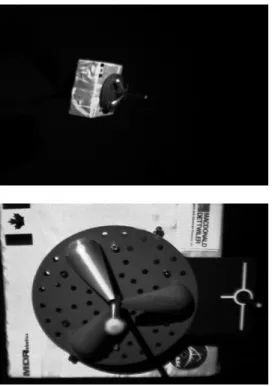
approach and show the results for a loop sequence shown in Figure 3.
Figure 3 First and last image of a sequence
Figure 4 Different views of the reconstructed camera trajectories and the accepted 3D points from the sequnce shown in Figure 3
Here we show the results of processing twenty five stereo views in a sequence of the grapple fixture. Figure 4 shows the reconstructed camera path and the 3D stereo features. The 3D features displayed in Figure 4 are all supported by the SFM analysis. They represent reliable data that was used to compute the camera path, since not all the original stereo features were reliable. We are in the process of performing more systematic experiments to evaluate the performance.
4.3
Acquisition
The monitoring mode estimates the motion of the satellite relative to the sensing system, but it does not resolve the pose parameters. The pose parameters determine how the satellite is oriented along its motion trajectory, and are essential to establish the location of the grapple fixtures. And docking interfaces.
In the acquisition mode, the pose of the satellite is approximated. This is more generally known as the pose determination problem. Using model-based methods, where the geometry is known, a solution can be formulated as a search within the pose space of the object. As the satellite can be positioned with 3 translational and 3 rotational degrees of freedom (i.e. 6 dofs) the search space is of a high dimension and computational efficiency is a major concern. That the satellite is isolated in the scene simplifies the problem somewhat, in that the translational components of the pose can be coarsely resolved. In the far range the satellite is visible but the distance is too great for the stereo algorithms to reliably extract sparse 3D points. In this case, appearance based methods such as those that use silhouettes [1] may be appropriate, particularly since the satellite can be segmented from the background. In the medium to near range, the 3D point data becomes more reliable than the intensity data, which can be corrupted by severe illumination effects. In these ranges, it is preferable to use techniques that are based upon the extracted sparse or dense 3D point data.
One approach is based Geometric Probing [7], where pose determination in range image data is formulated as template set matching. The satellite model is represented as a set of voxel templates, one for each possible pose. The set of all templates is composed into a binary decision tree. Each leaf node references a small number of templates. Each internal node
references a single voxel, and has two branches, “true” and “false”. The subtree branching from the “true” branch contains the subset of templates that contain the node voxel. Conversely, the subtree branching from “false” branch contains the subset of templates that do not contain the node voxel. Traversing the tree at any image location executes a Geometric Probing strategy that efficiently determines a good match with the template set. This technique has been demonstrated to be both efficient and reliable at identifying objects and their 6dof pose using dense range data.
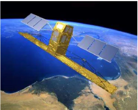
In order to improve efficiency and reliability, it may be possible to reduce the dimensionality of the search space by resolving some of the dofs prior to executing the Geometric Probing method. The Radarsat satellite (see Figure 5), for example, has very distinct major and minor axis, which can be identified in the data and used to resolve 2 of the 3 orientation parameters. For other satellite models, there may be identifiable features in either the range data (such as circular fixtures or planes) or intensity data (such as logos) that could be reliably extracted and used to resolved some of the positional ambiguity.
Figure 5 Radarsat-2
4.4
Tracking
In the tracking mode the vision system uses sparse data computed by the stereo sub-system and a 3D model of the observed object to compute its pose. The model is represented as set of geometrical shapes: boxes, cylinders, spheres and surface meshes (a hybrid model) [10]. For accelerated pose estimation the model may be pre-processed and represented as an octtree [2].
The tracker estimates pose of an object using a version of an Iterative Closest Point (ICP) algorithm that minimises the distance between two data sets [3]. In our case the first data set is obtained from the
sparse stereo sub-system and the second data set is a model of the object of interest. The tracker iteratively minimises the distance between the 3D data and the surface model. The first version of our tracking module used the hybrid model and relied on close form solutions for efficient and accurate computation of distances between the model and the data. The current version uses octtree models, which, at a small expense of lower accuracy, allow tracking pose at much higher rates than using the hybrid models. The tracker is initialised from an approximate estimate provided by the pose acquisition module based on Geometrical Probing module (see section 4.3). The tracker matches currently computed points with the surface model, and it does not require establishing and maintaining correspondences between detected 3D points and the model features. This significantly reduces its sensitivity to partial shadows, occlusion and local loss of data caused by reflections and image saturation. An adaptable gating mechanism eliminates outliers that are not part of the model. The tracker operates at rates of 1 Hz on a PC class computer and using ~1000 3D points.
The vision system was tested in the tracking mode using various calibrated image sequences. An image from a loop sequence (approach along Z-axis with rotation about the yaw axis) together with visualisation of the computed pose are shown in Figure 4. Additional information about these algorithms and conducted experiments can be found in a companion paper in this volume [2].
Figure 4 One of stereo images obtained during a loop sequence (right) and a virtual
image showing the computed model pose (left)
5
Concluding remarks
All algorithms for pose determination and tracking have been developed, and are currently being integrated into a test platform. This paper presents the system concept, design, algorithmic details, and some preliminary results of the integration and testing. There exist other solution approaches to satellite pose determination and tracking, such as systems that employ co-operative targets and active range sensors.
It is believed that the approach presented here offers a number of benefits over the alternatives. The system depends only upon standard video sensors, which are currently available and space qualified, and which will likely prove to be more reliable and less expensive than other exotic sensors. The system also does not require any targets to be placed on the satellites, which can be expensive. Further, there currently exist ~9,000 satellites in orbit which do not have suitable targets. Another benefit over the use of targets is that harsh lighting conditions can reduce the visibility of targets, while acquiring clear images of other parts of the satellite body.
6
References
[1] Abbasi S., Mokhtarian, F., "Affine-Similar Shape Retrieval: Application to Multiview 3-D Object Recognition", IEEE Transactions on Image Processing, vol. 10, no. 1, Jan. 2001, pp. 131-139. [2] Abraham M, Jasiobedzki, P., Umasuthan M.: "Robust 3D Vision for Autonomous Robotic Space Operations". in Proceedings of ISAIRIS- 2001. [3] Besl, P. & N. McKay, "A Method for Registration of 3-D Shapes", IEEE Transactions on Pattern Analysis and Machine Intelligence, vol. 14, no. 2, February 1992, pp. 239-256.
[4] Blais F, Beraldin J, Cournoyer L.: "Integration of a Trackinbg Laser Range Camera with the Photogrammetry based Space Vision System". SPIE Aerosense, vol. 4025, April 2000.
[5] Burtnyk N., Basran J., "Supervisory Control of Telerobotics in Unstructured Environments”, Proc. 5th International Conference on Advanced Robotics, Pisa, Italy, June 1991, pp 1420-1424.
[6]
http://oss1.tksc.nasda.go.jp/ets-7/ets7_e/rvd/rvd_index_e.html
[7] Greenspan, M.A., Boulanger, P., "Efficient and Reliable Template Set Matching for 3D Object Recognition", 3DIM99 : Proceedings of the 2nd International Conference on 3-D Digital Imaging and Modeling, Ottawa, Canada, Oct. 4-8, 1999, pp. 230-239.
[8] Hollander S.,"Autonomous Space Robotics: Enabling Technologies for Advanced Space Platforms", Space 2000 Conference, AIAA 2000-5079.
[9] Jasiobedzki P, Anders C: Computer Vision for Space Applications: Applications, Role and Performance. Space Technology v.2005, 2000
[10] Jasiobedzki P, Talbot J, Abraham M, "Fast 3D pose estimation for on-orbit robotics. International Symposium on Robotics", ISR 2000 Montreal, Canada, May 14-17, 2000
[11] Laurin, Denis G.; Beraldin, J.-Angelo; Blais, Francois; Rioux, Marc; Cournoyer, Luc. "A Three-Dimensional Tracking and Imaging Laser Scanner for Space Operations", SPIE Vol. 3707, pp. 278-289. [12] Madison R., Denoyer K, "Concept for Autonomous Remote Satellite Servicing", IAF Symposium on Novel Concepts for Smaller, Faster & Better Space Missions, Redondo Beach, CA, April 1999.
[13] McCarthy J.: Space Vision System. ISR-1998, Birmingham, UK.
[14] Oda M, Kine K, Yamagata F., "ETS-VII – a Rendezvous Docking and Space Robot Technology Experiment Satellite",46 Int. Astronautical Congress, Oct 1995, Norway, pp. 1-9.
[15] G. Roth, A. Whitehead, “Using projective vision to find camera positions in an image sequence”, Vision Interface 2000, pp. 87-94, Montreal Canada, May 2000.
[16] Sackos J, Bradley B, Nellums B, Diegert C: The Emerging Versatility of a Scanerless Range Imager. Laser radar Technology and Applications, SPIE v. 2748, pp. 47-60
[17] Whelan D.: Future Space Concepts
http://www.darpa.mil/tto/