Capture-Ready Power Plants - Options, Technologies and Economics
byMark Bohm
Bachelor of Engineering, Mechanical (Honors)
McGill University, 1999
Submitted to the Engineering Systems Division
in Partial Fulfillment of the Requirements for the Degree of
Master of Science in Technology and Policy
at the
Massachusetts Institute of Technology
June 2006
©2006 Massachusetts Institute of Technology
All rights reserved.
Signature
of
Author
...
.
....
:..
.. .
...
Technology and Policy Program, Engineering Systems Division
Monday, May 15t h, 2006
Certified by . ...
..
-
.....
...Howard J. Herzog
Principal Research Engineer
Laboratory for Energy and the Environment
Thesis Supervisor
Accepted
by...
...
...
...
~t~~ ~Dava J.
Newman
Professor of Aeronautics and Astronautics and Engineering Systems
Director, Technology and Policy Program
ARCHVE8
-ASW*J~
i S~mi
OF TECHNOLOGY IA t. I iii - - i I /IBMAT
J
I
LIBRARIES
I'
Capture-ready Power Plants - Options, Technologies and Costs
by
Mark C. Bohm
Submitted to the Engineering Systems Division on May 15th, 2006 in Partial Fulfillment of the Requirements for the
Degree of Master of Science in Technology and Policy
ABSTRACT
A plant can be considered to be capture-ready if, at some point in the future it can be
retrofitted for carbon capture and sequestration and still be economical to operate. The concept of capture-ready is not a specific plant design; rather it is a spectrum of investments and design decisions that a plant owner might undertake during the design and construction of a plant. Power plant owners and policymakers are interested in capture-ready plants because they may offer relatively low cost opportunities to bridge the gap between current coal-fired generation technologies without CO2capture to future
plants that may be built from the start to capture CO2, and reduce the risks of possible future regulations of CO2emissions. This thesis explores the design options,
technologies and costs of capture-ready coal-fired power plants.
The first part of the thesis outlines the two major designs that are being considered for construction in the near-term - pulverized coal (PC) and integrated gasification/combined
cycle (IGCC). It details the steps that are necessary to retrofit each of these plants for CO2 capture and sequestration. Finally, for each technology, it provides a qualitative
assessment of the steps that can be taken to reduce the costs and output de-rating of the plant after a retrofit.
The second part of the thesis evaluates the lifetime (40 year) net present value (NPV) costs of plants with differing levels of pre-investment for CO2capture. Three scenarios
are evaluated - a baseline supercritical PC plant, a baseline IGCC plant and an IGCC plant with pre-investment for capture. This analysis evaluates each technology option under a range of CO2tax scenarios and determines the most economical choice and year
of retrofit. The results of this thesis show that a baseline PC plant is the most economical choice under low CO2tax rates, and IGCC plants are preferable at higher tax rates. Little
difference is seen in the lifetime NPV costs between the IGCC plants with and without pre-investment for CO2capture.
The third part of this thesis evaluates the concept of CO2"lock-in". CO2lock-in occurs
when a newly built plant is so prohibitively expensive to retrofit for CO2 capture that it
will never be retrofitted for capture, and offers no economic opportunity to reduce the CO2 emissions from the plant, besides shutting down or rebuilding. The results of this
analysis show that IGCC plants are expected to have significantly lower lifetime CO2 emissions than a PC plant, given moderate (10-35 $/ton CO2) initial tax rates. Higher
(above $40) or lower (below $7) initial tax rates do not result in significant differences in lifetime CO2 emissions from these plants. Little difference is seen in the lifetime CO2
emissions between the IGCC plants with and without pre-investment for CO2capture.
Thesis Supervisor: Howard J. Herzog Principal Research Engineer
Laboratory for Energy and the Environment
ACKNOWLEDGEMENTS
I would like to first and foremost thank Howard Herzog for this guidance during my two years with the Carbon Sequestration Group. John Parsons provided valuable advice on how to properly approach the economics of this thesis, and Jim Katzer helped keep my ideas relevant and grounded in reality.
I would also like to thank the Carbon Sequestration Initiative for providing the generous financial support that allowed me to attend MIT and to make a contribution to the field of energy.
My office mates also deserve recognition - Ram Sekar, Mark de Figueiredo, Salem Esber, and Greg Singleton all contributed to making my many hours in E40 intellectually
stimulating and fun.
I would also like thank my parents for their support, and for encouraging me to pursue a
graduate degree. I am also indebted to my fiancee Victoria, whose constant love, patience and encouragement helped make my time at MIT so fulfilling.
TABLE OF CONTENTS
ABSTRACT ... ACKNOWLEDGEMENTS ... TABLE OF CONTENTS ... LIST OF FIGURES ... LIST OF TABLES ... LIST OF ACRONYMS ...1 INTRODUCTION AND SCOPE OF STUD'
..3 .. 5 ...6 ...8 ...9 10 11 1.1 OPTIONS FOR REDUCING CO2EMISSIONS FROM FOSSIL-FUELLED POWER PLANTS ... 13
1.2 SCOPE OF THIS STUDY ... 14
1.2.1 Capture-ready plants - definition, technologies and costs ... 15
1.3 DEFINITION OF A 'CAPTURE-READY' POWER PLANT ... 17
2 PULVERIZED COAL PLANTS...19
2.1 PULVERIZED COAL TECHNOLOGY ... 20
2.2 CAPTURE OF CO2FROM A PULVERIZED COAL PLANT ... 24
2.2.1 Solvent-based CO2capture ...25
2.3 RETROFITTING OF EXISTING PC PLANTS, AND CAPTURE-READY OPTIONS . ... 30
2.3.1 Retrofit issues and capture-ready opportunitiesfor post-combustion PC ... 31
2.3.2 Retrofit issues and capture-ready opportunities for oxyfired PC ... 35
2.3.3 Retrofit issues and capture-ready opportunities for all PC plants ... 39
2.4 ECONOMICS AND PERFORMANCE OF RETROFITTED AND CAPTURE-READY PC PLANTS ... 42
2.5 CURRENT INVESTMENTS AND ACTIONS IN CAPTURE-READY PC PLANTS . ...43
3 INTEGRATED GASIFICATION/COMBINED CYCLE PLANTS ...45
3.1 IGCC TECHNOLOGY ... 46
3.2 ECONOMICS OF IGCC PLANTS ... 50
3.3 EXISTING IGCC PLANTS ... 51
3.4 CAPTURE FROM IGCC PLANTS ... 53
3.5 RETROFITTING OF IGCC PLANTS AND CAPTURE-READY OPTIONS ... 55
4 ECONOMIC AND ENVIRONMENTAL EVALUATION METHODOLOGY AND ASSUMPTIONS ... 63
4.1 ANALYSIS METHODOLOGY ... 66
4.1.1 . .71 Investm ent costs ... 4.1.2 Operation and maintenance costs ...77
4.1.3 ... Fuel costs ... 77
4.1.4 . .77 M akeup p lant ... 4.1.5 Economic parameters ...78
4.1.6 . .79 M odeling inputs ... 5 RESULTS OF ECONOMIC AND ENVIRONMENTAL EVALUATION ... 80
5.1 OPTIMAL TECHNOLOGY CHOICE FOR A GIVEN CARBON TAX SCENARIO ... 80
5.2 IMPACT OF TECHNOLOGY CHOICE ON OPTIMAL YEAR OF RETROFIT ... 83
5.3 IMPACT OF TECHNOLOGY CHOICE ON LIFETIME CO2EMISSIONS ... 85
6 CONCLUSIONS AND AVENUES FOR FUTURE WORK ...89
... I. ... ... @... ... BB88....j...m~8...a I8... ... I... ·... m...
6.1 CONCLUSIONS ... . 89
6.2 AVENUES FOR FUTURE W ORK ... 9...91 7 REFERENCES ... .. 93
LIST OF FIGURES
FIGURE 2-1 FORECASTED UNITED STATES COAL PLANT ADDITIONS BY DECADE, 2003-2030 IEIA 20061 .... ... I I FIGURE 3-1 YEAR OF CONSTRUCTION AND AVERAGE SIZE OF COAL-FIRED POWER PLANTS IN THE US [EIA
200611920061 ... 20061.19
FIGURE 3-2 SIMPLIFIED PROCESS FLOW DIAGRAM OF A PULVERIZED COAL STEAM GENERATION POWER
PLANT2PLANT ... 2PLANT21
FIGURE 3-3 FORECASTED COAL PLANT ADDITIONS BY TECHNOLOGY, 2005-2025 [NETL 20051 ...23
FIGURE 3-4 PROCESS FLOW DIAGRAM FOR A PULVERIZED COAL PLANT WITH SOLVENT CO2CAPTURE ... 26
FIGURE 3-5 PROCESS FLOW DIAGRAM FOR AN OXYFIRED PULVERIZED COAL PLANT WITH CO2CAPTURE.. 28
FIGURE 3-6 OPTIONS FOR RETROFITTING EXISTING POWER PLANTS ... 31
FIGURE 3-7 IMPACT OF DISTANCE OF CO2SEQUESTRATION ON COE ...39
FIGURE4-1 PROCESS FLOW DIAGRAM FOR IGCC PLANT ... 47
FIGURE 4-3 PROCESS FLOW DIAGRAM FOR IGCC PLANT (RAW GAS CO-SHIFT) ...53
FIGURE 4-4 IMPACT OF DISTANCE OF CO2 SEQUESTRATION ON COE FOR A RETROFITTED IGCC PLANT. 62 FIGURE 5-1 BENCHMARK FUTURE CARBON TAX REGIMES VS. OPTIMAL TECHNOLOGY CHOICE SEKAR 2005].67 .67...2005
FIGURE 5-2 IMPACT OF RETROFIT ON TOTAL PLANT COST FOR SUPERCRITICAL PC PLANT WITH POST-COMBUSTION CAPTURE...73
FIGURE 5-3 IMPACT OF RETROFIT ON TOTAL PLANT COST FOR BASELINE IGCC PLANT ...75
FIGURE 5-4 IMPACT OF RETROFIT ON TOTAL PLANT COST FOR IGCC PLANT WITH PRE-INVESTMENT ...76
FIGURE 6-1 40-YEAR NPV COST OF PLANT VS. INITIAL CARBON TAX LEVEL -2% TAX GROWTH RATE ...81
FIGURE 6-2 40-YEAR NPV COST OF PLANT VS. INITIAL CARBON TAX LEVEL -5% TAX GROWTH RATE ...82
FIGURE 6-3 ECONOMICALLY OPTIMAL TECHNOLOGY CHOICE VS. FUTURE CARBON TAX REGIME ...83
FIGURE 6-4 OPTIMAL YEAR OF RETROFIT VS. INITIAL CARBON TAX LEVEL -2% GROWTH RATE ...84
FIGURE 6-5 OPTIMAL YEAR OF RETROFIT VS. INITIAL CARBON TAX LEVEL - 5% GROWTH RATE ... 85
FIGURE 6-6 LIFETIME CO2EMISSIONS VS. INITIAL CARBON TAX LEVEL - 2% GROWTH RATE ...87
LIST OF TABLES
TABLE 3-1 OPERATING CONDITIONS AND EFFICIENCIES OF PC PLANTS ... 21
TABLE 3-2 SURVEY OF PERFORMANCES, COSTS AND EFFICIENCIES FOR PC GENERATION TECHNOLOGIES.... ... 24
TABLE 3-3 SURVEY OF PERFORMANCE, COSTS AND COE FOR PC WITH CO2CAPTURE ... 27
TABLE 3-4 SURVEY OF PERFORMANCE AND ECONOMICS OF PC OXYFIRED STUDIES ... 29
TABLE 3-5 RETROFIT ISSUES AND CAPTURE-READY OPTIONS FOR PC WITH AMINE CAPTURE ... 32
TABLE 3-6 IMPACT OF STEAM CYCLE ON POST-COMBUSTION PC RETROFIT DE-RATING AND EFFICIENCY. 33 TABLE 3-7 CHANGES TO MAJOR COMPONENTS IN A PC BOILER FOR OXYFIRED RETROFIT ... 36
TABLE 3-8 IMPACT OF STEAM CYCLE ON AN OXYFIRED PC RETROFIT PERFORMANCE MIT 20061 ... 37
TABLE 3-9 SUMMARY OF RETROFIT STUDIES FOR PC PLANTS ... 42
TABLE 4-1 DESIGN CRITERIA OF LEADING GASIFIER TYPES MAURSTAD 20051 ... 48
TABLE 4-2 SUMMARY OF STUDIES FOR IGCC PLANTS WITHOUT CO, CAPTURE ... 51
TABLE 4-3 TECHNICAL AND COST DETAILS OF OPERATING IGCC PLANTS ... 52
TABLE 4-4 CHANGES TO MAJOR COMPONENTS IN AN IGCC RETROFIT AND CAPTURE-READY OPTIONS .... 57
TABLE 5- 1 PERFORMANCE CHARACTERISTICS OF EVALUATED CASES BEFORE AND AFTER RETROFIT ... 71
TABLE 5-2 CAPITAL COSTS, OPERATING COSTS AND PERFORMANCE OF CASES BEFORE AND AFTER RETROFIT ... 76
TABLE 5-3 OPERATION AND MAINTENANCE COSTS FOR STUDY CASES ... 77
TABLE 5-4 COSTS AND PERFORMANCE OF GREENFIELD MAKEUP PLANTS ... 78
TABLE 5-5 ECONOMIC ARAMETERS USED FOR MODELING ... 78
TABLE 5-6 MODELING INPUTS ... 79
LIST OF ACRONYMS
ASU Air separation unit
AEP American Electric Power
AGR Acid gas removal
BOP Balance of plant
CC Carrying charge
CO2 Carbon dioxde
COE Cost of electricity
DOE US Department of Energy
EIA Energy Information Agency, US Department of Energy
EPA US Environmental Protection Agency
EPRI Electric Power Research Institute
ESP Electrostatic precipitator
ETS European Trading Scheme FGD Flue gas desulfurization GE General Electric
GW Gigawatt
HHV Higher heating value
HP High pressure
IGCC Integrated gasification combined cycle
kWe Kilowatt electric
KWh Kilowatt-hour
LP Low pressure
MEA Monoethanolamine
MMBtu Million British thermal units
MPa Megapascal
Mt Megatonne (metric)
MWe Megawatts electric
MWh Megawatt-hours
NCC National Coal Council
NGCC Natural gas combined cycle
NPV Net present value
O&M Operation and maintenance
PC Pulverized coal ppm Parts per million
SC Supercritical
SCR Selective catalytic reduction
SO2 Sulfur dioxide
SubC Sub-critical
TPC Total plant cost
1
INTRODUCTION AND SCOPE OF STUDY
Interest in the construction of coal-fired power generation has increased significantly in recent years, sparked by continually increasing demand for electricity, combined with volatile prices of other fossil fuels, including natural gas and oil, the difficulties surrounding the construction of nuclear facilities, and the current challenges of
availability and pricing of new generation technologies, such as solar and wind. In the
United States, it is expected that overall demand will increase from 3,840 billion kilowatt-hours in 2005 to over 5,600 billion kilowatt-hours in 2030 [EIA 2006]. This correlates into approximately 250 GW of new generation capacity.' Of this new capacity, the EIA estimates that 106 GW will be met through the construction of coal-fired plants. This corresponds to an average construction rate of eight 500 MW coal-fired plants per year over the next twenty-five years. Figure 1-1 illustrates the expected growth of coal-fired power plants over the next 25 years.
Figure 1-1 120 (- 100 c-O 80 o 40 = 20 -0
Forecasted United States coal plant additions by decade, 2003-2030
[EIA 2006]
2003-2010
2011-2020
2021-2030
Year
' Assumes an 85% capacity factor for new plants
11
Worldwide, the expected installed capacity of coal-fired plants is expected to increase by
over 40% in the next 20 years, and by 2025 it is expected to exceed 1400 GW of installed capacity [EIA 2005].
While coal-fired power plants offer significant cost and energy security advantages, they are also major sources of criteria air pollutants such as NOx and SO2, air toxics such as
mercury, and greenhouse gas emissions, namely CO2. With an expected lifespan of 40
years or more these plants will account for a significant portion of future global rises in greenhouse gas concentrations if no actions are taken to capture the CO2 from them. This
issue is compounded by the fact that the large majority of both existing and proposed plants are expected to be prohibitively expensive or technically infeasible to retrofit for CO2 capture and sequestration at a later point [MIT 2006]. This problem can be
addressed if, during the initial design and construction phase, the plant is designed to be
'capture-ready', which this study defines as follows:
A plant can be considered 'capture-ready' if, at some point in thefuture it can be
retrofittedfor carbon capture and sequestration and still be economical to operate.
The concept of 'capture-ready' is not a specific plant design; rather it is a spectrum of investments and design decisions that a plant owner might undertake during the design and construction of the plant. Further discussion of the range of 'capture-ready' options is
discussed in a later section. If carbon prices are high enough it is expected that any plant will be more economical to retrofit than to operate. It is also expected that, in the event
that a plant has an overly large output de-rating and increase in operating costs (including
fuel), it would be more economical to decommission the plant and build a more efficient plant in its place.
Policymakers have identified the concept of capture-ready power plants as a possible tool to mitigate the long-term emissions of greenhouse gasses. This was recognized by members of the G8 nations at the 2005 Gleneagles Conference on clean energy and
sustainable development. In their plan of action, released at the conclusion of the conference, the members identified that the "acceleration of the development and commercialization carbon capture and storage technology" should be pursued by "investigating the definition, costs and scope for 'capture-ready' plants and the consideration of economic incentives" [G8 2005]. Gaining a better understanding of what appropriate steps to build capture-ready plants is a priority to members of the G8 because new power plant installations will be around for decades to come. In addition, plants that are not designed to be 'capture-ready' could prove to be prohibitively
expensive to retrofit in the future, resulting in either delayed reductions in CO2 emissions,
or stranded generation assets.
From an owner perspective, the technology choice is driven primarily by economics. The uncertainties surrounding the additional costs and actions required to build a capture-ready facility and the uncertainty surrounding retrofit costs are expected to be significant barriers to its adoption. Added to the uncertainty of upfront capital and future retrofit costs are the uncertainties of future carbon tax levels and growth rates. In the case of a privately financed and owned plant, each of these variables increases the uncertainty of future cash flows, which increases the required investment return and the project hurdle rate for the proposed plant.
1.1 Options for reducing CO
2emissions from fossil-fuelled power plants
Several options are available to power plant owners to reduce emissions from these plants, each having different investment and performance trade-offs. For coal, these options include:
The construction of high-efficiency plants. This includes IGCC with advanced heat recovery, or ultra-supercritical PC plants, reducing the emissions of CO2per
MWh up to 40% as compared with the average existing coal-fired power plant2.
2 Assumes a fleet average efficiency of 33%, new build efficiency of 46% (HHV)
* The construction of plants now with carbon capture and sequestration technologies, reducing emissions of CO2per MWh by up to 90%.
* Rebuilding of existing plants at some point in the future to capture CO2emissions,
or to use less C02-intensive fuels such as natural gas, or CO2-free technologies
such as nuclear, wind or hydro.
* The construction of capture-ready coal-fired power plants, which
accommodations are made during the initial design phase to reduce the cost and performance penalty of retrofitting CO2capture at a later date.
This thesis attempts to describe the options, technologies and economics of the final option - capture-ready coal-fired power plants.
1.2 Scope of this study
For plant owners and investors, the two questions surrounding the construction of capture-ready coal-fired power plants are:
- What are the range of actions and investments that can be made during the design
and construction of a plant to reduce the future costs and energy penalties of retrofitting for CCS?
- Do these investments and actions make economic sense, given current
understandings and uncertainty of future regulations on CO2emissions?
Policymakers and regulators, in addition to the above questions, are also interested in the following:
4 What role, if any can capture-ready plants play as a transition step towards the
long-term reduction of CO2 emissions from the power sector?
4 Will capture-ready plants have an impact on the political feasibility of moving
- Is there a role for investments in capture-ready technologies in developing nations
by international agencies, such as the World Bank?
This thesis attempts to address these issues in two sections. The first section defines the technologies and options for capture-ready plants by exploring the capital and technical requirements for capture-ready for both traditional pulverized coal (PC) and integrated gasification and combined cycle (IGCC) power plants. The second part of this thesis develops a methodology to determine under which scenarios would it be economically
efficient to build a capture-ready plant. It also applies the methodology to a number of
technology options, and determines what the impacts of the technology selections are on lifetime costs and CO2emissions of each case. It also evaluates the concept of CO2
"lock-in", which occurs when a newly built plant is so prohibitively expensive to retrofit for CO2capture that it will never be retrofitted.
1.2.1 Capture-ready plants - definition, technologies and costs
Although it may be technically possible to retrofit any coal-fired power plant for CO2
capture and sequestration, those that require a very significant investment to retrofit, or sustain an overly large penalty on the plant's net generating output may prove
uneconomical to justify a retrofit. Owners of these plants may decide to rebuild the plant and replace the major components such as the boiler and steam turbines with either higher efficiency units (such as ultra-supercritical boilers and high efficiency turbines) or a completely new generating technology such as an IGCC plant with carbon capture and
storage (CCS) or a natural gas combined cycle (NGCC) plant. In either case, the owner will incur significant costs in stranding the existing assets that otherwise would have continued operating and producing electricity, possibly for several more decades.
Given the current best estimates of capture performance and costs, it is expected that most of the existing fleet of traditional pulverized coal (PC) generating units in the United States, currently over 300 GW of generating capacity will not be suitable
candidates for CCS retrofit [EIA 2005, MIT 2006]. It is possible that new capture and
separation technologies may be developed, such as aqueous ammonia or ITM oxygen separation, but significant hurdles still exist in their development, and it is very likely that action will need to be taken to control CO2emissions before they are ready for
commercial deployment.
Capturing CO2from existing natural gas and oil plants may be even less attractive,
because of their already lower CO2emissions per MWh, lower flue gas concentration of
CO2, along with their lower capacity factors and smaller per kWe initial investment.
Clearly, coal-fired plants are of more interest.
CO2capture from power plants will not be done unless there are clear incentives for
power plant owners to take action, either through taxes (such as a carbon tax) or through regulation (such as a cap and trade scheme). Power plant owners have been required to reduce emissions in the past, however. Sulfur dioxide (SO2) emissions in the United
States have been restricted by a cap and trade system, which allocates a certain amount of total permitted amount of SO2emissions for all plants. Plants are allocated permits based
on a percentage of their previous year emission levels, and then are able to buy or sell their permits, depending if the value of the permits exceeds or not the value of the electricity sales the plant would otherwise need to forgo. This system has been very effective, reducing SO2emissions by 50% since 1980, with prices of the permits
fluctuating between 70 and 210 $/t SO2 between 1995 and 2004 [EPA 2006]. The costs
of the permits are much lower than what many power companies were predicting when the trading system was first proposed, and the cost savings have been driven by a
combination of reduced capital costs of SO2control equipment, as well as through the use
of low-sulfur coal. Many policymakers have suggested that the same trends could be seen in the control of CO2emissions.
1.3 Definition of a 'capture-ready' power plant
As defined in the beginning of this chapter, a plant can be considered 'capture-ready' if, at some point in the future it can be retrofitted for carbon capture and sequestration and still be economical to operate. Given that this existing coal-based fleet appears to be unsuitable for retrofitting CCS without significant leaps in capture technologies, it is important to evaluate and understand the steps that can be taken to ensure that any fossil fuelled power plant built in the future is capture-ready. This is especially important as it is estimated that over 80 GW of coal-fired power generation will be installed over the next two decades in the United States [EIA 2005a]. Power plant owners and
policymakers want to understand if investing in capture-ready technology makes sense as an intermediary step as we move towards ever more stringent controls on greenhouse gas emissions.
These investments, if made wisely, will act to reduce the costs that owners will assume in order to comply with future CO2 regulations, and could also accelerate the rate at
which CO2 capture is adopted, reducing total cumulative emissions. In order for a power
plant to be considered capture-ready, technology choices, plant layout and location decisions are made in the initial design and construction to reduce the costs and performance penalties associated with retrofitting the plant for carbon capture and sequestration at some point in the future. The number of actions and level of investment can vary significantly because the level of capture-readiness and technology choices that an owner will decide to employ depends on a number of issues, including:
- The investor's choice of a project hurdle or discount rate
- Expectation of the timing and stringency CO2 regulations and/or taxes
- Ability to recover investment costs at a future date (such as in a regulated market) - Owner's level of comfort with new, unproven technologies
- Cost and quality of available coal
- Availability and cost of CO2 transportation and appropriate sequestration sites
The following two chapters describe in detail the options and technologies for both pulverized coal and IGCC coal-fired power plants.
The vast majority coal-fired power plants built to date in the world are pulverized coal steam generation units, and it is expected that this technology will be the predominant choice for the construction of new coal-fired plants in the near term. There are currently
1,526 pulverized coal plants in the United States, with an average size of 220 MWe, and
an average operating efficiency of 33% [EIA 2006]. The average age of these plants is
40 years old, with the oldest unit still in service constructed in 1935. The mean
generating capacity of each plant increased approximately 8 times from the 1950's to the 1970's, then leveled off. The bulk of the capacity was built in the 1960's and 1970's, with construction tapering off in the 1980's. Very little construction of new coal-fired power plants has occurred in the past 25 years. Figure 2-1 illustrates the range of ages and average generation capacities of coal-fired plants still in operation in the United
States.
Figure 2-1 Year of construction and average size of coal-fired power plants in the US [EIA 2006] A fln
-uu
An500
i Number of v -40U >4 plants 40 __ constructedo
C)300 a
C.)200
200 ) C) Averagea)_
Generating
100 >s Capacity 0 before 1950- 1960- 1970- 1980- After 1950 1959 1969 1979 1989 1990Year of commission
192
PULVERIZED COAL PLANTS
stuv
350
X 300 m250
4-o 200
-E150
z 100
50 02.1 Pulverized coal technology
Pulverized coal plants produce electricity by first producing high pressure, high
temperature steam in a large water wall boiler that is fired by pulverized coal and air. The
steam produced in the boiler is then piped to a Rankine cycle steam turbine that drives a generator to produce electricity. Depending on the design, the boiler might have between one and three reheat cycles that reheat the steam leaving a higher-pressure stage of the turbine, returning the steam to a lower-pressure stage. Once the steam has finished passing through the turbines it is then condensed to liquid water in a condenser and
returned to the boiler to complete the cycle.
Performance improvements for PC plants have generally come from increasing the temperature and pressure of the steam produced by the boiler, which increases the thermodynamic efficiency of the system. Reheat cycles can also be added that heat the steam between higher and lower pressure sections of the turbine, further increasing the power output and efficiency of the boiler. Older style boilers, known as subcritical boilers, do not heat the water beyond the supercritical point of water in the boiler; rather a separate flashing tank is used to produce the steam after the heated water has left the boiler. Supercritical and ultra-supercritical plants heat and pressurize the water beyond the supercritical point (above 22.1 MPa), negating the need for a separate flashing stage before the water is sent to the turbine. These types of plants are able to do this because of recent developments in higher strength materials and better process controls that allow for higher steam temperatures and pressures. Table 2-1 outlines the operating pressures, temperatures and the operating efficiencies of current sub-critical, supercritical and
ultra-supercritical PC plants. These values are typical only; the efficiency of the plants depends on a number of factors, including coal quality, condensing cycle type and water
temperature (if water cooled), number of re-heat cycles in the turbine, size of the plant,
Operating conditions and efficiencies of PC plants
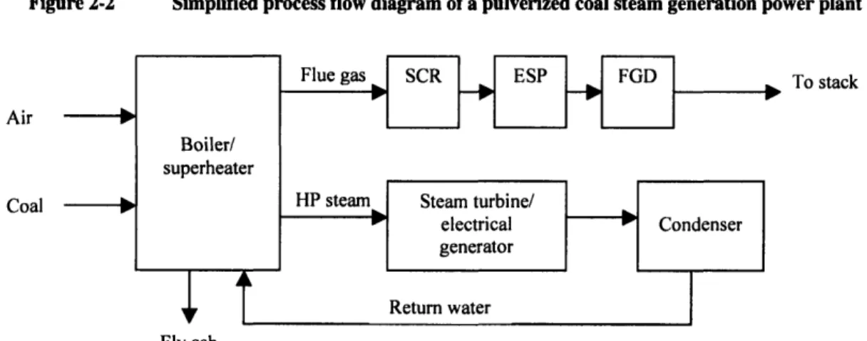
The flue gas, after having exited the boiler, is treated to control emissions of certain criteria air pollutants. This treatment usually involves a three-part process, depending on the level of pollutant control required. The plans for new build plants include the
following three flue gas cleanup steps.
--) Selective catalytic reduction (SCR) for NOx control
- Particulate removal with an electrostatic precipitator (ESP)
- Flue gas desulfurization (FGD) for sulfur dioxide removal
Figure 2-2 illustrates a simplified process flow diagram for a typical pulverized coal-fired power plant, and outlines the major components.
Figure 2-2 Simplified process flow diagram of a pulverized coal steam generation power plant
Air
Coal
To stack
Fly ash
21
Steam cycle Pressure (MPa) Temperature (C) Efficiency
(%, nnV)
Sub-critical 16.5 540 36 - 38
Supercritical 24.1 565 39 - 41
Ultra-supercritical 31.0 595 43 - 45
Pulverized coal plants offer a number of advantages over more advanced coal-fired generation technologies, namely IGCC, outlined in Section 4. These advantages
include:
- Lower capital costs and risk of cost overruns during the construction phase because of the proven track record of these plants, having been constructed over the past 70 years.
- Lower operation and maintenance costs
- Long track record of high reliability and plant availability
- Ability to use a wide range of coal qualities without significant modifications to the plant
- Ability for existing operators to use current staff expertise in operating these facilities
It is because of these advantages that most of the proposals for new construction of coal-fired plants in both the US and elsewhere in the world are of the traditional pulverized coal design. NETL has reported that 75% of the 87 GW of new coal-fired capacity that will be installed in the next 20 years will be of the pulverized coal variety [NETL 2005].
Figure 2-3 illustrates the expected breakdown of these additions by technology, and the vast majority of these plants are expected to be of the subcritical pulverized coal variety.
Figure 2-3 Forecasted coal plant additions by technology, 2005-2025 [NETL 2005] 140 120 100 80 0 60 E
z
40
Z
20 U- mm MMUM Kul~Sub-critical PC Supercritical CFB IGCC
PC
Technology
The costs and performance of pulverized coal plants have been estimated in a number of recent studies. It is important to note that the capital costs in these reports do not reflect the recent significant increase in fuel and steel costs.
Table 2-2 summarizes the major US studies that have evaluated the costs and performance of pulverized coal technologies for sub-critical, supercritical and ultra-supercritical PC plants.
23
- - ^ - - * - ffi - - w..w.^u A.. ^
Survey of performances, costs and efficiencies for PC generation technologies
2.2 Capture of CO
2from a pulverized coal plant
The sequestration of CO2requires that the CO2be in a single phase flow, with minimal
amounts of non-condensible gasses such as nitrogen, argon and oxygen. In addition, it also needs to be free of contaminants such as water that could corrode the pipeline. It is unclear if sulfur dioxide needs to be removed, as some studies have suggested that the presence of the contaminant could negatively affect the porosity of the sequestration injection zone, reducing the capacity of the CO2reservoir [MIT 2006].
MIT NETL NCC MIT EPRI NCC Rubin MIT EPRI Simbeck
Study 2006 2002 2004 2006 2002 2004 2004 2006 2002 2003
Cost year 2005 2002 2003 2006 2000 2003 2004 2006 2000 2000
Technology subC subC SubC SC SC SC SC USC USC USC
Efficiency (%, HHV) 34.3% 37.4% 36.7% 38.5% 40.5% 39.3% 39.3% 43.3% 42.8% 43.1% TPC ($/kWe) 1280 1114 1230 1330 1143 1290 1076 1360 1161 1290 Annual CC (%onTPC) 15.1% 16.8% 14.3% 15.1% 15.5% 14.2% 16.6% 15.1% 15.5% 15.0% Fuel price ($/MMBtu) 1.5 0.95 1.5 1.5 1.24 1.5 1.27 1.5 1.24 1.0 Capacity factor (%) 85% 85% 80% 85% 65% 80% 75% 85% 65% 80% Electricity Price3 Capital charge (cents/kWh) 2.60 2.52 2.51 2.70 3.10 2.62 2.71 2.76 3.15 2.77 O&M (cents/kWh) 0.75 0.8 0.75 0.75 1.00 0.75 0.79 0.75 0.95 0.74 Fuel (cents/kWh) 1.49 0.87 1.39 1.33 1.04 1.30 1.10 1.18 0.99 0.79 COE (cents/kWh) 4.84 4.19 4.65 4.78 5.15 4.67 4.61 4.69 5.09 4.30
3As reported in studies
The two leading technologies that have been proposed for CO2 separation from
pulverized coal plants are solvent-based separation and oxyfiring. Solvent-based
separation uses a solvent, such as an amine, to separate the CO2post-combustion from
the flue gas. Oxyfired combustion uses relatively pure oxygen (95% or higher) for
combustion in place of atmospheric air. The resulting flue gas is primarily CO2, with
trace amounts of oxygen and other gases that can be flashed off during the compression
of the CO2.
2.2.1 Solvent-based CO2capture
Solvent-based CO2 capture systems remove CO2from the flue gas by chemically
absorbing the CO2with a solvent, typically an amine such as monoethanolamine (MEA).
After scrubbing the CO2 from the raw flue gas, the solvent is then regenerated by heat,
which releases the CO2from the amine solution. The steam is generally supplied by
diverting some of the steam that would have otherwise driven the lowest pressure steam
turbine section. The CO2 is released at ambient pressure, and needs to be compressed and
dried to be ready for pipeline transport to a suitable sequestration site
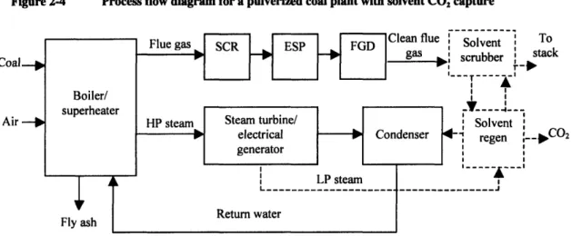
Figure 2-4 illustrates a process flow diagram for a pulverized coal power plant with a solvent CO2 capture system.
Figure 2-4 Process flow diagram for a pulverized coal plant with solvent CO2capture
An advantage of solvent-based CO2 capture and sequestration is that current power plant
designs to be used with little modifications to the front end of the plant. The boiler design, and steam cycle remain the same. In addition, solvent capture of CO2 from PC
plants has been used on a commercial scale for many years to produce CO2for industrial
applications, although it has generally been done on a small scale, capturing the CO2
from a small proportion of the flue gas stream.
Some of the issues that face the use of solvents for CO2capture and sequestration include
the costs of the scrubber and solvent, controlling solvent loss and the significant amount
of steam that is used in stripping the CO2 from the saturated solvent. The costs and
performance penalties can be minimized by selecting high-efficiency ultra-supercritical boiler designs that produce less flue gas (and CO2) per unit of electrical output than
current boiler designs. These boilers have been in use in Japan and Europe, but have not yet been deployed in North America.
The use of solvents for CO2 capture has been characterized in a number of engineering
studies. Table 2-3 outlines the cost and performance characteristics from these studies.
Coal
Air
, To
Survey of performance, costs and COE for PC with CO2capture
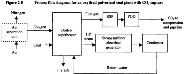
Oxyfired CO2 capture
In an oxyfired pulverized coal plant the oxygen required for combustion is provided by an air separation unit that separates the oxygen from the other gases present in
atmospheric air, which is primarily nitrogen, along with some other trace gases. After the flue gas is treated to remove particulate matter, it is dried, flashed to separate out non-condensable gasses and compressed for transport. It is uncertain whether or not the sulfur compounds would have to be removed from the flue gas; there is potential that the presence of sulfur in the CO2 being sequestered could affect its injectivity, but this issue
has not been studied definitively. There may also be permitting issues surrounding the injection of a SO2, which is a criteria air contaminant. Figure 2-5 is a simplified process
flow diagram for an oxyfired pulverized coal plant with CO2 capture.
27
MIT NETL MIT EPRI MIT EPRI Simbeck
Study 2006 2002 2006 2002 Rubin 2006 2002 2002
Cost year basis 2005 2002 2005 2000 2004 2005 2000 2002
Technology SubC SubC SC SC SC USC USC USC
Plant output (MW, net)
Efficiency (%, HHV) 25.1% 26.6% 29.3% 28.9% 29.9% 34.1% 31.0% 33.8%
PC($/kW) 2230 2086 2140 1981 1729 2090 1943 2244
nnualCC(%onTPC) 15.1% 16.8% 15.1% 15.5% 16.6% 15.1% 15.4% 15.0%
Fuel price ($/MMBTU) 1.5 0.95 1.5 1.24 1.27 1.5 1.24 1.0
Capacity Factor (%) 85% 85% 85% 65% 75% 85% 65% 80% Electricity price4 Capital charge (cents/kWh) 4.52 4.72 4.34 5.38 4.36 4.24 5.27 4.80 O&M (cents/kWh) 1.60 1.67 1.60 1.71 1.6 1.50 1.61 1.28 Fuel (cents/kWh) 2.04 1.22 1.75 1.46 1.45 1.60 1.36 1.01 COE (cents/kWh) 8.16 7.61 7.69 8.55 7.41 7.34 8.25 7.09
4As reported in studies
Figure 2-5 Process flow diagram for an oxyfired pulverized coal plant with CO2capture Nitrogen
---i
t---Air ' Oxygenseparation
r
"
unit ,It
Coal
-*
AirFlue gas ESP FGD co2to
compression and pipeline
HP
steam |Steam turbine/
electrical Condenser generator Return water Boiler/ superheater Fly ash
The use of oxyfiring for CO2capture may have both technical and cost advantages over
solvent-based post-combustion capture technologies. Cryogenic air separation is a proven technology that is used currently on a large scale for industrial purposes, and the costs and operation of these units are well understood. The boiler can also be designed to be smaller and less expensive to construct because of the higher combustion rates and temperatures that are possible with pure oxygen combustion
Some of the difficulties surrounding oxyfiring is the lack of operational experience. To date, no commercial scale oxyfired PC plant has been constructed. The higher
temperatures and properties of oxyfired combustion may pose some difficulties for materials selection and design, although it is expected that through the use of exhaust gas recirculation that it should be able to properly control the combustion temperature to prevent damage to the boiler. Boiler air leakage is also a concern for oxyfired PC plants. Typically, boilers run under a slight negative pressure to prevent hot combustion gasses from escaping into the power building. The excess air that enters the boiler is not a concern for air-fired boilers, but in the case of an oxyfired boiler this air would dilute the CO2leaving the boiler with non-condensable gasses such as nitrogen and oxygen, which
would then have to be separated during compression, adding to the capital and energy costs of the plant.
There are also large power requirements for the air separation unit. Some of these power needs can be made by integrating the air separation unit with the steam turbine, using shaft power to drive the air compressors in the air separation unit, but this integration makes the design and operation of the plant more complex. Several studies have evaluated oxyfired combustion for new build plants. A summary of these studies is
presented in Table 2-4.
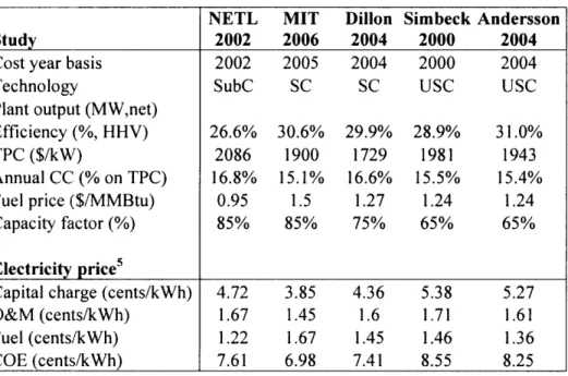
Table 2-4 Survey of performance and economics of PC oxyfired studies
29
NETL MIT Dillon Simbeck Andersson
Study 2002 2006 2004 2000 2004
Cost year basis 2002 2005 2004 2000 2004
Technology SubC SC SC USC USC
Plant output (MW,net)
Efficiency (%, HHV) 26.6% 30.6% 29.9% 28.9% 31.0%
TPC ($/kW) 2086 1900 1729 1981 1943
nnual CC' (% on TPC) 16.8% 15.1% 16.6% 15.5% 15.4%
uel price ($/MMBtu) 0.95 1.5 1.27 1.24 1.24
Capacity factor (%) 85% 85% 75% 65% 65%
lectricity price5
apital charge (cents/kWh) 4.72 3.85 4.36 5.38 5.27
O&M (cents/kWh) 1.67 1.45 1.6 1.71 1.61
Fuel (cents/kWh) 1.22 1.67 1.45 1.46 1.36
COE (cents/kWh) 7.61 6.98 7.41 8.55 8.25
2.3 Retrofitting of existing PC plants, and capture-ready options
With over 300 GW of existing PC plants in the United States, the ability to economically retrofit existing plants for CO2capture could be an effective method by which CO2
emissions can be curtailed, and the growth of atmospheric CO2concentrations
constrained. Some of the issues that face owners considering retrofitting their PC plants for carbon capture and sequestration include:
- Capital costs and the associated financing of the capture equipment
- Large reduction in the net output of the plant, and the need to acquire makeup power
- Increased operation and maintenance costs
- Increased total and dispatch cost of electricity (COE)
- Location and access to a suitable sequestration site
- Timing and length of the downtime required for the retrofit
- On-site availability of space
- Design and age of existing plant
The issues surrounding the retrofitting of these plants are significant, and the suitability for retrofit for each plant would have to be evaluated independently, as some of these factors would be larger in magnitude, or have greater impacts for some plants compared to others.
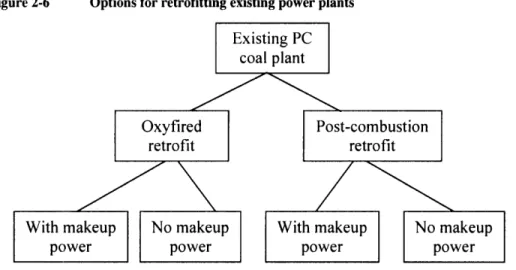
The two major categories of retrofit technologies that can be used for existing PC plants are the same as the greenfield technologies that were described earlier in this report -oxyfuel combustion and solvent-based post-combustion capture. In addition to the basic capture technologies, several variations of each has been considered by several studies. These include the use of auxiliary natural gas boilers or combined cycle gas turbines (NGCC) to provide the additional steam needed for stripping the CO2in the regeneration
the additional equipment and CO2compression. Figure 2-6 illustrates the leading options
that exist fr retrofitting a plant for CO2 capture.
Figure 2-6 Options for retrofitting existing power plants
The differences between a plant design optimized for no consideration of capture (a baseline plant) and a capture-ready plant are expected to be significant and these differences will have considerable impacts on the costs, operability and output of a baseline plant that has been retrofitted for COE. In addition, the optimal design of a capture-ready plant depends on the technology that is expected to selected for capture when the plant is ultimately retrofitted. The following three sections describe these differences for issues specific to post-combustion, oxyfuel combustion and issues
universally applicable to both technologies. It also discusses the capture-ready options for all of the technologies.
2.3.1 Retrofit issues and capture-ready opportunities for post-combustion PC
While no major technical hurdles exist for retrofitting PC plants for capture with post-combustion amine scrubbing, the expected de-rating, capital requirements and increase in operation and maintenance costs (including fuel) are expected to pose significant
challenges to owners and policymakers if and when decisions need to be made to reduce CO2 emissions from these facilities. Some of these impacts can be minimized for plants
that have not already been built by employing capture-ready designs and technologies.
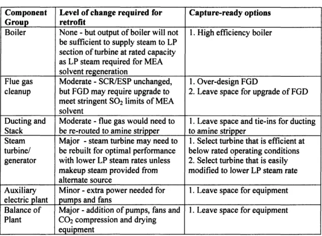
Table 2-5 provides a high-level, component-by-component overview of the issues surrounding the retrofit of a PC plant with amine capture, and the capture-ready options that can be deployed to minimize the impacts of these issues.
Table 2-5 Retrofit issues and capture-ready options for PC with amine capture
A more detailed description of the issues surrounding retrofit and capture-ready opportunities for PC plants with post-combustion catpture are described below.
Boiler
The conversion efficiency of the power plant is heavily dependent on the selection of the boiler. Sub-critical boilers, which run at pressures below the supercritical point of water (22.1 MPa) dominate the current fleet of US and world coal plants, but offer significantly lower conversion efficiencies than supercritical or ultra-supercritical boilers (see Table
Component Level of change required for Capture-ready options Group retrofit
Boiler None - but output of boiler will not 1. High efficiency boiler
be sufficient to supply steam to LP
section of turbine at rated capacity as LP steam required for MEA solvent regeneration
Flue gas Moderate - SCR/ESP unchanged, 1. Over-design FGD
cleanup but FGD may require upgrade to 2. Leave space for upgrade of FGD meet stringent SO2 limits of MEA
solvent
Ducting and Moderate - flue gas would need to 1. Leave space and tie-ins for ducting Stack be re-routed to amine stripper to amine stripper
Steam Major - steam turbine may need to 1. Select turbine that is efficient at turbine/ be rebuilt for optimal performance below rated operating conditions
generator with lower LP steam rates unless 2. Select turbine that is easily makeup steam provided from modified to lower LP steam rate alternate source
Auxiliary Minor - extra power needed for 1. Leave space for equipment electric plant pumps and fans
Balance of Major - addition of pumps, fans and 1. Leave space for equipment Plant CO2 compression and drying
2-1). For a given electrical output, these lower conversion efficiencies relate directly to higher CO2emissions, and correspondingly larger capital and energy costs and a larger
de-rating after retrofit. Table 2-6 illustrates the impact of selecting a higher efficiency boiler on the de-rating and efficiency of the plant after retrofit with post-combustion capture.
Table 2-6 Impact of steam cycle on post-combustion PC retrofit de-rating and efficiency [MIT 2006]
Technology Sub-critical Supercritical
Ultra-supercritical Baseline plant
Net output before retrofit (MW) 500 500 500
Efficiency before retrofit (%, HHV) 35.0% 39.2% 44.0%
CO2Emissions (t/MWh-e) 0.91 0.81 0.72
Retrofitted plant
Retrofit de-rating (%) 41.5% 36.0% 33.0%
Net output after retrofit (MW) 293 315 335
Efficiency after retrofit (%, HHV) 20.5% 25.0% 29.5%
CO2Emissions (t/MWh-e) 0.06 0.05 0.04
Flue gas cleanup
The requirements for flue gas cleanup are more stringent with an amine capture system than is required by current source emission standards in the US. The primary concern is SO2, as the amine scrubbing solvent can become loaded with SO2, which can severely
degrade the CO2 removal performance of the capture system. Acceptable levels of SO2in
the flue gas are 10 ppm, significantly lower than what is required by air quality
regulations. In order to address this gap, the flue gas cleanup system would have to be upgraded, requiring additional investments in flue gas desulfurization equipment.
Approaches for capture-ready that can be taken for this technology would be to over-design the flue gas desulfurization unit to ensure that the required sulfur levels can me met without additional capital investments at the time of retrofit. Another option would be to leave additional space in the vicinity of the FGD unit to allow sufficient room for upgrades without major modifications to the existing layout of the plant.
Ducting and stack
The ducting and stack would have to be modified in the event of a retrofit, as the amine
stripper would have to be inserted between the flue gas desulfurizer and the stack. This may pose difficulties if little room exists for the equipment; additional ducting may be required to locate the amine stripper in a location adjacent to the plant.
Steps that can be taken to make the plant more capture-ready include specifying tie-ins in the existing ductwork, and leaving additional space between the FGD and the stack to accommodate the placement of the amine scrubber during the retrofit.
Steam turbine/electrical
generator
One of the major impacts of a retrofit to capture with a post-combustion capture system is the steam requirements of the CO2stripper. A 20-30% reduction in the electrical output
of the steam turbine/electrical generator is expected due to the diversion of significant amounts of low-pressure steam to the reboilers of the MEA CO2recovery system
[Alstom 2002]. One option that exists to address the reduction in low-pressure steam going to the turbine in the event of a retrofit is the addition of a supplementary boiler or combined cycle natural gas turbine to provide the necessary make-up steam. This may not be feasible because of the additional capital required for the extra boiler, as well as the costs of fuelling this additional unit, especially if it is fuelled by natural gas.
Alternatively, the low-pressure section of the turbine may need to be rebuilt to accept the lower steam rate.
A capture-ready option would be to specify a steam turbine that is able to operate at an acceptable efficiency at lower heat rates; it is unclear at this point as to what design changes would be required to satisfy this requirement.
Auxiliary electric plant
The addition of post-combustion capture would require additional electric capacity to power the extra pumps and fans that would be necessary to run the CO2 stripping
equipment. It is not expected that these changes would be very significant, however. Cost savings could be realized in the retrofit if in the initial design phase extra space is allocated fr the additional equipment.
2.3.2 Retrofit issues and capture-ready opportunities for oxyfired PC
Less operational experience exists with oxyfired PC plants as compared to post-combustion capture, but initial studies indicate that the oxyfired technology may have efficiency and cost advantages over post-combustion that may make it the preferred technology for retrofit. Table 2-7 provides a high-level, component-by-component overview of the issues surrounding the retrofit of a PC plant with oxyfiring, and the capture-ready options that can be deployed to minimize the impacts of these issues.
Changes to major components in a PC boiler for oxyfired retrofit
A more detailed description of the issues surrounding retrofit and capture-ready opportunities are described below.
Boiler
As is the case with a post-combustion retrofit, the conversion efficiency of the power plant is heavily dependent on the selection of the boiler. Table 2-6 illustrates the impact of selecting a higher efficiency boiler on the de-rating and efficiency of the plant after retrofit with oxyfired technology.
Component Level of change required for Capture-ready options
Group retrofit
Boiler Major - air handling system 1. Highest efficiency boiler required for CO2recycle, boiler design
may need to be improved to 2. Low leakage boiler design
minimize air leaks 3. Leave space for equipment
Flue gas Minor - SCR may no longer be 1. Install FGD system that can cleanup necessary, or require changes to work with both flue gas
run with CO2rich gas compositions
Ducting and Moderate - addition of CO2 1. Leave space and tie-ins for
Stack recycle system required CO2 recycle system
Steam Minor - same amount of steam No capture-ready options exist turbine/ would be delivered to turbine. for steam turbine
generator Shaft power might be harnessed for ASU
Auxiliary Major - changes to provide power 1. Leave space for equipment electric plant to ASU and pumps
Balance of Major - addition of pumps, fans 1. Leave space for equipment Plant and equipment for CO2
compression, non-condensables separation and drying
Impact of steam cycle on an oxyfired PC retrofit performance [MIT 20061
Flue gas cleanup
An oxyfired PC plant, unlike a plant with post-combustion amine capture does not require sulfur control for the capture equipment to work properly. It is possible, however
that the sulfur present in the flue gas (as SO2) would need to be controlled as it is a
criteria air pollutant, and there may be issues surrounding the permitting of an injection
well that has SO2present in the CO2to be sequestered. In addition, it is uncertain whether
or not the sulfur compounds would have to be removed from the flue gas; there is potential that the presence of sulfur in the CO2 being sequestered could affect its
injectivity but this issue has not been definitively studied.
If flue gas desulfurization is required, it is uncertain as to whether or not the design of currently used systems would work with the new (primarily CO2) flue gas composition
without requiring major modifications. This issue should be further studied to determine if steps can be taken to ensure that the FGD system initially specified and construction is able to operate efficiently after retrofit.
37
Technology Sub-critical Supercritical
Ultra-supercritical Baseline plant
Net output before retrofit (MW) 500 500 500
Efficiency before retrofit (%, HHV) 35.0% 39.2% 44.0%
CO2Emissions (t/MWh-e) 0.91 0.81 0.72
Retrofitted plant
Retrofit de-rating (%) 36.0% 32.1% 28.6%
Net output after retrofit (MW) 321 340 357
Efficiency after retrofit (%, HHV) 22.4% 26.6% 31.4%
CO2Emissions (t/MWh-e) 0.09 0.07 0.06
Ducting and stack
The ducting and stack would have to be modified in the event of an oxyfired retrofit, as a flue gas recycling system would have to be installed in order to control the combustion temperatures in the boiler. This may pose difficulties if no room is left for this extra piping during the initial construction of the plant. Steps that can be taken to make the plant more capture-ready include specifying tie-ins in the existing ductwork and leaving additional space to accommodate the placement of the ducting and fans required for the flue gas recycle during the retrofit.
Steam turbine/electrical
generator
A major advantage of an oxyfired retrofit over a post-combustion amine retrofit is the fact that the steam heat rate to the steam turbine is unaffected, and the steam cycle should be able to operate without any modifications. There are some efficiency advantages that can be gained by integrating the air separation unit by using shaft power from the steam turbine for air compression. Providing allowances for this integration is a capture-ready option that should be considered.
Auxiliary electric plant
The addition of oxyfired capture would require additional electric capacity to power the additional pumps and fans that would be necessary to run the air separation unit, flue gas recycle fans and the CO2compressors. These power draws are expected to be quite
significant, and major changes are expected to be required to the auxiliary electric plant to supply the required power. A capture-ready option for this component includes leaving extra space for the additional electrical equipment.
2.3.3 Retrofit issues and capture-ready opportunities for all PC plants
Proximity to suitable sequestration site
The costs of transporting and sequestering CO2 can vary significantly, depending on how
far and how technically difficult it is to dispose of the CO2produced in the power plant.
Typical costs for a pipeline capable of handling the emissions from a 500 MWe power
plant are expected to run in the 33 M$ per 100 km and can add a significant amount to
the total COE [Heddle 2003]. Figure 2-7 illustrates the impact of pipeline transport distance on the levelized cost of electricity of a retrofitted sub-critical, supercritical and
ultra-superctritical PC plant. Figure 2-7
1.4
1.2
R1
3ft
0
C0.8
foU
4-0
.
4
0
u 0.2
U
0Impact of distance of CO2Sequestration on COE
-
SubC
SC PC
USC PC
100 150 200 250 300 350 400 450 500
Pipeline length (km)
Downtime requiredfor retrofit
The amount of time that a plant is required to be offline for a retrofit may cause
significant operational difficulties for the plant owner. If the required downtime is short enough (under 2 or 3 months) to fit within one of the shoulder seasons where electricity demand is lower, the impact on the owner may be significantly less, as the owner's remaining capacity is more likely to be sufficient to make up for the shortfall.
Alternatively, power could be purchased from another producer, generally at lower rates than during peak months. It is expected that a post-combustion retrofit would take less time than an oxyfired retrofit, because much of the equipment required for a post-combustion retrofit could be installed on-site without requiring the plant to go offline. In addition, no major changes are required to the boiler. An oxyfired retrofit is expected to take significantly more time as major changes are required to the boiler and the air
handling system.
The allocation of space on the plant site as a capture-ready step is expected to reduce the
time required for retrofit, as the additional space could allow for the placement of equipment before tying into the original plant, and reduce the number and complexity of major equipment replacements and re-routing.
Plant layout and available space
As outlined in Section 2.3.2, many existing plants have been built on space-constrained
sites. These plants may not have the additional space available to optimally locate
post-combustion capture equipment, which can add 25-40% to the footprint of a plant. In addition, many of these plants have been retrofitted previously for pollution control,
namely flue gas desulfurization but some have also had selective catalytic reduction
(SCR) units added to control NOx emissions. These additions may have further reduced the amount of available space for the addition of a post-combustion capture unit.
These space constraints, as a worst-case scenario, may prevent the retrofitting of a particular plant. In other cases it may be required to move, modify or replace major
components of the plant, which would add significantly to the costs of the retrofit. It may also increase the amount of downtime required for the retrofit, further impacting the economics of this option.
The capture-ready option is to leave additional space for the equipment and for the construction equipment that would be used during the retrofitting process. Land costs
generally make up a very small portion of the total investment cost for a power plant. NETL estimated land costs for a new coal-fired plant to be $1.3 million, providing 200
acres for the plant, which accounted for 0.2% of the total cost of a PC plant [Parsons 2002]. Providing an additional 50 acres of land for capture equipment is a conservative
(high) estimate of the amount of land required, and would add no more than 0.05% to the
total cost of the plant, or $0.4 million. The changes to the plant layout may involve a
larger level of investment, primarily to the piping and ducting. As a first-order estimate this study assumes that this would add 10% to the cost of the piping and ducting to a plant. NETL estimates that the costs of the ducting, stack and piping for a PC plant would be $34.6 million. This would translate into an additional $3.5 million investment to build a plant with a capture-ready layout. The total capture-ready investment for both the additional land and changes to the piping and ducting layout would be approximately $3.6 million.
2.4 Economics and performance of retrofitted and capture-ready PC plants
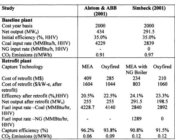
Two recent studies [Simbeck 2001 and Alstom 2002] evaluated the technical and economic aspects of retrofitting existing pulverized coal power plants. The studies focused on sub-critical PC plants, as these units comprise over 95% of the existing US stock of PC plants. Both post-combustion MEA capture and oxyfired combustion retrofits were considered. The studies were quite different in their approach for post-combustion capture; Simbeck specified the use of a natural gas boiler to provide the steam required by the MEA stripper, whereas the Alstom study assumed that the steam would be provided from the original boiler, with the steam turbine being derated to accommodate the reduction in steam available for power production. Table 2-9 summarizes the technical and economic parameters of the plants evaluated in the report.
Table 2-9 Summary of retrofit studies for PC plants
Study Alstom & ABB Simbeck (2001)
(2001)
Baseline plant
Cost year basis 2000 2000
Net output (MWe) 434 291.5
Initial efficiency (%, HHV) 35.0% 35.0%
Coal input rate (MMBtu/h, HHV) 4229 2839
NG input rate (MMBtu/h, HHV) - 0
CO2Emissions (t/MWh) 0.91 0.97
Retrofit plant
Capture Technology MEA Oxyfired MEA with Oxyfired
NG Boiler
Cost of retrofit (M$) 409 285 234 210
Cost of retrofit ($/kW-e, after 1604 1044 803 1060
retrofit)
Efficency after retrofit (%,HHV) 20.5% 22.5% 24.1% 23.3%
Net output after retrofit (MWe) 255 255 291.5 198.5
Fuel input rate -Coal (MMBtu/hr, 4228.7 4140 2840 2892
HHV)
Fuel input rate -NG (MMBtu/hr, - - 1289 0
HHV)
Capture efficiency (%) 96.2% 93.8% 90.8% 91.5%
It is important to note that the expected efficiency penalty of a retrofit is much higher than a greenfield plant. This is true for both post-combustion and oxyfired retrofits.
In the case where the existing plant proves to be unsuitable for retrofit, more aggressive approaches exist. These include rebuilding the existing unit to include CO2 capture and
improve the overall technology on the site, resulting in an optimally sized and balanced
unit. This could be done by upgrading to a supercritical PC or an ultra-supercritical PC
with post-combustion CO2capture, by upgrading to oxy-fired supercritical technology, or
by installing IGCC with CO2 capture. In this case, very little of the original plant is
retained, and most of the major components such as the boiler, steam turbine, air
handling equipment and much of the accessories would need to be replaced. Components that could be re-used include the on-site support facilities, coal handling equipment and stack, but these generally respresent a small fraction of the total plant cost - 10% or less [Simbeck 2005]. The performance of these rebuilt units would be the same as greenfield plants, and have not been summarized for this study.
2.5 Current investments and actions in capture-ready PC plants
Although there is considerable interest in capture-ready plants in both North America and in Europe, there are not as of yet any firm plans for the construction of this type of plant. Saskpower, the publicly owned utility in the Canadian province of Saskatchewan had announced the construction of a capture-ready plant, to be online by 2013 [Clayton 2005]. Because of newer federal government directives on CO2 emissions in order to
meet Canada's Kyoto Protocol requirements Saskpower has moved instead to perform an engineering design study for a coal plant with CO2 capture, and forgo the capture-ready
concept [Stobbs 2006]. Before forgoing the capture-ready options, the steps that Saskpower had outlined to make the plant capture-ready included:
* Allocation of space for capture equipment
* Addition of connection points for steam, flue gas extraction to capture equipment
* Selection of steam turbine that could be readily retrofitted for optimized performance under reduced steam loads, which would occur after a retrofit
The project was being built to accommodate whatever technology would be most appropriate for capture when the plant was retrofitted, be it an amine-based post-combustion capture, oxyfired post-combustion with flue gas capture, or another technology that is currently not technically or economically feasible. No cost estimates had been
developed for the capture-ready investments before the decision to change the design of the plant had been made.
3
INTEGRATED GASIFICATION/COMBINED CYCLE PLANTS
Integrated gasification and combined cycle (IGCC) technology for electrical power production is an advanced design that uses coal gasifiers, fuel gas processing subsystems, a combustion turbine, heat recovery steam generator and a steam turbine. Both the combustion turbine and the steam turbine drive electrical generators, much the same way a natural gas combined cycle power plant operates.
IGCC technology offers advantages over PC plants for CO2 capture as the CO2can be
separated at higher partial pressures, reducing the amount of capital required and the energy penalty for capture. Less operational experience exists with IGCC plants, however and they are more complicated to operate and construct than a traditional PC plant. Some of the issues that are specific to retrofitting IGCC plants for CO2capture
include:
* The water-gas shift reaction of the syngas and CO2removal reduces the heating
value of the syngas by approximately 15%, which would cause a de-rating of the combustion turbine [EPRI 2003].
* The convective and radiative gas coolers, if present, may no longer be required, as the addition of water into the syngas to produce steam for the water-gas shift reaction may sufficiently reduce the temperature of the syngas.
* The acid gas removal system would require the addition one more stage to
remove CO2 in addition to H2S. An MDEA system (if present) may need to be
removed and replaced with 2-stage Selexol-type acid gas removal system. * The combustion turbine combustors may need to be changed and a blade retrofit
may be needed in order to operate on diluted hydrogen gas.
* Compressed air for the air separation unit may no longer be available from the turbine, necessitating the addition of a parallel air compressor.
* Re-arrangement of existing equipment may be required to accommodate the
addition of the water-gas shift reactors, second acid gas removal stage and CO2
compression and drying equipment.
![Figure 2-1 Year of construction and average size of coal-fired power plants in the US [EIA 2006] A fln -uuAn 500 i Number of -40U >4 v plants 40 __ constructed o C) 300 a C.) 200 200 ) C) Average a)_ Generating 100 >s Capacity 0 before 195](https://thumb-eu.123doks.com/thumbv2/123doknet/14199184.479642/19.918.171.815.653.1009/figure-construction-average-number-constructed-average-generating-capacity.webp)
![Figure 2-3 Forecasted coal plant additions by technology, 2005-2025 [NETL 2005] 140 120 100 0 80 60 E z 40 Z 20 U- mm MMUM Kul~](https://thumb-eu.123doks.com/thumbv2/123doknet/14199184.479642/23.918.167.714.150.505/figure-forecasted-coal-plant-additions-technology-netl-mmum.webp)
![Table 2-6 Impact of steam cycle on post-combustion PC retrofit de-rating and efficiency [MIT 2006]](https://thumb-eu.123doks.com/thumbv2/123doknet/14199184.479642/33.918.148.759.304.546/table-impact-steam-cycle-combustion-retrofit-rating-efficiency.webp)