Development of An Improved Swept RF Tagging System and its Musical
Applications
By Laurel P. Smith
B.S., Electrical Engineering and Computer Science (2001)
Massachusetts Institute of Technology
Submitted to the Department of Electrical Engineering and Computer Science In Partial Fulfillment of the Requirements for the Degree of
Master of Engineering in Computer Science and Electrical Engineering
BARKER At the
Massachusetts Institute of Technology
January 2002
MASACUSETTS IiSTI TUTE
OF TECHNOLOGY
JUL
3 1 2002
LIBRARIES @ 2002 Massachusetts Institute of Technology. All rights reservedThe author hereby grants to M.I.T. permission to reproduce and distribute publicly paper and electronic copies of this thesis
and to grant others the right to do so.
Signature of Author ... ... ... Department of E Iectrical Engineering and Compute>r\cience
January 1, 2002
C ertified by ... . ...
Joseph A. Paradiso Ytncipal Research Scientist, Media Arts and Sciences Thejis Supervisor
Accepted by.
Anhur C. Smith
Acknowledgements
First and foremost I would like to thank Joe Paradiso for giving me the opportunity to work
on this project as well as his help, knowledge, faith, and support throughout, especially considering
my constrained military schedule, Leila Hasan for being the best office mate I could ever ask for
and so much more, Matt Hancher for always answering my questions, Mark Feldmeier for his
analog guidance and writing such interesting e-mails, Candyland for giving me a home when I had
none, Vis Taraz and Marc Rios for always causing the necessary ruckus, Romy Shioda for your
incredible musicianship and playing crazy music with me for my five years here, the MIT Music
Department, the Herbs, and everyone else I have played with for being such inspirations and the
reason my MIT experience was the pleasure it was, and finally, the United States Air Force for
Table of Contents
1. Introduction 6
1.1 Introduction to Magnetic Tags as Sensors 8
2. Passive Tag Readers 10
2.1 Implementation of a Ringdown Tag Reader 10
2.2 Swept Frequency Tagging 11
3. Improvements to the Swept RF Tag Reader 15
3.1 Processor Upgrade 17
3.2 Dynamic Baseline Sampling 17
3.3 Frequency Drift 19
3.4 Alterations to Inductive Sensing Circuitry 25
4. Early Tag Reader Applications 28
4.1 Tangible Media and musicalBottles 29
4.2 Musical Trinkets 30
5. Musical Navigatrics Error! Bookmark not defined.
5.1 Technical Implementation 36
5.2 Musical Implementation 38
5.3 Evaluation of Musical Navigatrics 48
6. Future Development 58
6.1 Improvements 58
6.2 Expansion- Multi-Coil Geometries 60
Conclusions 66
Appendix A: Schematics 69
Appendix B: Code 68
B.A Cygtag.h: Microprocessor Header Selections 69
B.B Cygtagm.c: Microprocessor Code 71
Appendix C: MAX Code 87
C.A General Patches 88
C.B Sequencing Patches 91
C.C Voice Patches 98
Table of Figures
Figure 2-1: Bridge Circuit 13
Figure 2-2: Analog Output for Swept Frequency Tagging 14
Figure 3-1: Most Recent Tag Reader 16
Figure 3-2: Block Diagram of Tag Reader 17
Figure 3-3: Swept Frequency Output Baseline 19
Figure 3-4: Exponential Curve for Sweep Generation 21
Figure 3-5: Comparison of Frequency Drift With and Without Compensation 22
Figure 3-6: Sweep Output with Calibration Tags 25
Figure 3-7: Old 6 Coil Tag Reader 27
Figure 4-1: Tangible Media Group's musicalBottles 30
Figure 4-2: Tagged Objects used in Musical Trinkets 32
Figure 4-3: Multi-user Interaction with the Musical Trinkets 34
Figure 5-1: Musical-Navigatrics Setup 37
Figure 5-2: Voice Tag Interactions 40
Figure 5-3: MAXNote Tables for Note Determination 41
Figure 5-4: Note Tags 42
Figure 5-5: Effects Tags 43
Figure 5-6: Control Tags 47
Figure 6-1: Magentic Field Lines and Non-Uniform Interaction 62
Figure 6-2: Magnetic Field Lines from a Helmholtz Configuration 64
Chapter
1
Introduction
Recent history has seen tremendous expansions in the capability and power of
computational machines in a short amount of time. In merely 50 years, we have seen the
introduction of computers and their evolution from being giant, expensive, and exclusive university
research platforms to becoming one of the most ubiquitous tools today. Computers are now widely
available everywhere that technology reaches and are used for a vast array of activities. However,
despite this growth in both computational power and computers' popularity, the computer interface
has remained largely stagnant. The present day graphical user interface is tied to 2-D tracking and
display technology, with the keyboard and mouse as the primary mode of interaction. New
investigations into computer human interfaces to provide more natural and sensible interactions are
looking to move beyond these restrictive boundaries.
Not unlike computers, in the past 20 years, the popularity of entirely electronic music has
skyrocketed. As electronic music takes advantage of the new ubiquity of processing power, the
wide capabilities for sound manipulation have made it an attractive creative platform while the
drop in processor cost has made it possible to purchase powerful music computation engines for an
accessible price. The number of people using electronic synthesizers and production tools has
dramatically risen, and along with that, electronic music performances have become common
well-attended events. Yet despite this outburst in the creativity of new sounds, styles, and tools,
electronic music interfaces have remained largely the same: buttons, knobs, keyboards and the
full scope of what processors have made musically available. Most electronic musicians, unlike
acoustic musicians, remain largely unable to interact with the rich sonic soundscape of this new
music at an expressive and gestural level that is reciprocal to the expressivity, complexity, and
form of the music itself. In creation and performance they remain tied to small interfaces that
allow for only minimal physical interaction. Although an expressive physical interface is not a
requirement for interesting music, the physical interactions between an instrument and a performer
are key to a rich rewarding experience, as any acoustic player has experienced.
Worse is live performance. While such performances are increasingly popular, musicians
continue to have difficulty finding means to translate their music from the dry interaction of the
production studio to an interesting, entertaining, and rousing live show. Some musicians resort to
transcribing the music for live instruments, putting dancers on the stage, or using graphical imagery
to distract from the lack of on-stage activity. A worst-case performance, which is not by any
means uncommon, consists of the performers standing in front of computers and interacting
through the standard GUI. Not surprisingly, this does not generate much viewer engagement.
Recognizing the need for new interactive interfaces, the Responsive Environments Group,
directed by Dr. Joe Paradiso at the MIT Media Lab, has designed and built a swept-frequency
passive tag reader[1]. This device is capable of continuously sensing and identifying at least 20
distinct small passive tags within a limited range in real-time. The basic operation is achieved by
driving a search coil at various frequencies to create an AC magnetic field in the active region and
then introducing small magnetically-coupled resonators (e.g. LC circuit tags or magnetostrictiors)
into this field. If the field is driven at a tag's resonant frequency, the tag will draw energy from the
magnetic field, altering the current through the search coil. This change in coil inductance can be
of change corresponds to the amount of coupling, which is determined by the tag's distance and
orientation to the field. As only one tag will couple with the coil at a specific frequency, sweeping
through a range of frequencies allows simultaneous detection of tags; these sweeps can be
performed fast enough to provide real-time interaction. Due to their small size, these resonant tags
can be embedded into a wide range of objects, creating new tangible interfaces[2] and, consequently, new musical controllers.
1.1 Introduction to Magnetic Tags as Sensors
Magnetic tagging systems are already a well-established technology. A wide variety and
range of applications already exist in which tags are commonly used. Tagging system are available
to perform complex tasks, as in the case of active tagging systems that have been developed for
accurate motion capture, to simple ones, such as the "Electronic Article Surveillance" (EAS)
tagging systems often used to detect shoplifting.
Passive tags, as opposed to battery powered or wired active tags that often require
potentially complicated hardware, are tags that draw power transmitted by an antenna to trigger
some kind of detectable response. They generally fall into two categories, chip-based radio
frequency identification, RFID[3] tags or chip-less resonant tags. RFID tags work by powering a
CMOS state-machine chip, which then transmits some sort of unique identifying response. Removing the micro-controller essentially results in a magnetically-coupled resonance tag, a tag
whose identification is made only by the resonant frequency at which it draws power.
In order to work as a tangible or musical interface, the tagging system must be able to detect
a variety of tags in real-time over a reasonable distance. RFID tags, due to the time required for
them to draw the power necessary for the chip and provide an anti-collision response when more
option is magnetically-coupled resonant tags. The primary drawback of magnetically-coupled
resonant tags is the limited number of identities available, as the tag's response is not precise. The
relation of a tag's coupling strength to the width of the response in a frequency sweep is described
as the tag's
Q.
Using higherQ
tags allows for more tags to fit within the same frequency sweep. Although resonant tags have been limited to predominantly EAS systems, other deviceshave explored using passive, magnetically-resonant tags for detection and tracking purposes. The
classic Wacom Tablet[4] uses resonant tags to track and identify coded whiteboard pens, while one
of its descendants in the musical controller world, Don Buchla's Marimba Lumina[5], embeds tags
into the marimba mallets enabling them to act as MIDI controllers. Both these interactions
Chapter 2
Passive Tag Readers
Development of passive resonant tags to explore new possibilities for computer-human
interfaces was begun by Dr. Joseph Paradiso and Kai-Yuh Hsiao within the Responsive
Environments research group at the MIT Media Lab. In order to serve as a tangible interface, the
primary two requirements for a successful tag reader are that it has to be able to detect and track a
substantial number of tags, and that it has to do it in real-time. Along with that, the reader should
be able to detect a continuous range of coupling amplitudes and needs to be relatively stable. There
have been two approaches to passive tag reading explored throughout the course of their research:
pulsed ringdown devices and continuous swept-frequency architectures.
2.1 Implementation of a Ringdown Tag Reader
A first attempt[1] at implementing a passive tag interface was done by exploiting "ringdown" to identifying multiple tags. The operational basis for a ringdown reader derives from
transmitting a magnetic pulse at the resonant frequency of a tag. The tag is effectively energized
by the pulse and releases this energy as an electronic ringdown response when the driving magnetic pulse stops. This resonant response is small, but can be clearly detected by a sensitive listening
reader.
Using this principle, a ringdown tag reader was built that would "ping" or transmit at a
specific discrete known frequency and then switch off, allowing read circuitry to listen for and
detect the ringdown that would occur if a tag was present at that transmit frequency. In order to
tags. To better match the read coil to the desired driving resonance, a ladder of capacitors and
triacs was added to enable dynamic retuning.
With this strategy, the ringdown tag reader was able to successfully detect multiple tags
continuously and could complete a full ping-listen cycle 30 times a second. The system suffered,
however, as the detection process for one tag took roughly 12 milliseconds. Thus, to remain
operating in real-time, the number of tags is very limited. Assuming a minimum 10 Hz update rate,
only 8 tags could be used. Also, the system was particularly sensitive to the frequency drift
inherent in the drive system and high-Q tags, as transmission needed to occur at specific, discrete,
well-tuned spots. Although the ringdown reader worked well, these drawbacks prevented it from
fully meeting the needs of the desired tangible interface.
2.2
Swept Frequency Tagging
Recognizing the restrictions placed on the ringdown system, it was decided to move from
discrete frequency steps to a continuous sweep. As there is now continuous "pinging," a
swept-frequency reader required a change in its detection mechanism, using a continuously operational
inductive bridge instead of the discretely switched listening circuitry used with the ringdown
approach. The swept frequency tag reader that was built[ 1] sweeps from roughly 400kHz down to
around 50 kHz. The sweep frequency curve is shaped exponentially, as this helps balance the tag
coupling between the high and low frequencies. This problem stemmed from the fact that a linear
sweep will drive far more wave cycles of a high frequency than a low frequency given the same
amount of time. Using a linear sweep resulted in the higher frequencies being driven more
strongly, an effect countered by reshaping the sweep to spend more time at lower frequencies so
the received signal from the tags at all frequencies so they are all optimized for maximum response
in minimum time. Lastly, while the ringdown reader preferred magnetostrictors (a common
materials-based EAS tag) due to their high
Q and strong ringdown response, the swept-frequency
reader was better suited for LC (coupled inductor-capacitor) tags. Although the signal produced bymost LC tags is usually not as strong as for magnetostrictors, the ringdown, which can interfere
with subsequent tags encountered later in the sweep, is reduced, and the tuning of LC tags is fairly
easy, clean, stable, and reliable.
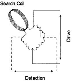
As indicated, tag detection is achieved using an inductive bridge (see Figure 2-1). As the
tag perturbs the magnetic field, it alters the current running through the search coil. Four inductors,
one of which is the sense, or search, coil, form the inductive bridge. The non-search-coil leg of the
bridge serves as a tunable reference that does not interact with the resonant tags. This enables the
comparison of the current through the two legs, leading to the determination of the differential
voltage and thus signal presence and strength. This signal is further processed to transform it into a
well-sized clean DC signal as shown in Figure 2-1. The original tag reader uses a PIC 1 6C73 and
Search Coil
I
-
.-Detection
6 5 4 3 2 -1 rime (meeC)
Figure 2-2 Analog Output for Swept Frequency Tagging (with multiple tags present)
presence and strength. This signal is further processed using analog gain and filter stages that
transform it into a well-sized clean DC signal as shown in Figure 2-2 The original tag reader uses a
PIC16C73 and later a PIC16C83 micro-controller to interpret this signal strength and send information on tag frequency and strength to a host PC through a serial link.
This swept frequency tag reader achieved the primary tangible interface goals fairly well.
The reader completes a full sweep of the spectrum 30 times a second, correctly sensing and
identifying tags in real-time. The number of tags that can be sensed is now, unlike the ringdown
reader, limited primarily by frequency overlap between tag responses. Due to parasitic
capacitances, the frequency at which the tag will respond is not entirely specific, and the tag's
Q,
determines the tightness of the response. Depending on their components, LC tags have varyingQ
thus the resonant frequencies need to be appropriately spread out to minimize interaction between
tags. Despite this problem, the swept-tag reader, sweeping across roughly a decade in frequency, is
still able to easily detect as many as 20 tags at a time. This number could be expanded
considerably by increasing the range of the frequency sweep, and by more careful selection and
creation of tags. Without slowing the real-time refresh rate, increasing the sweep range will reduce
the time spent at any given tag resonance, weakening the response but allowing for more tags.
Detection is also continuous, and at present has a reasonable range of roughly 12" from the search
Chapter 3
Improvements to the Swept RF Tag Reader
While the first implementation of the tag reader by Dr. Paradiso and Hsiao was certainly
successful, there remained a number of improvements that could be made to its final design[ 1]. As
part of this thesis, a new tag reader, based on the previous version, has been built in order to rectify
some of the identified problems, as well as enable new means for improved tag reading capability.
These improvements are aimed at increasing the tag reader's sensitivity and dynamic range,
stability, and expandability. The circuit can be broken down into three functional areas: frequency
sweep generation, inductive sensing, and system control. All three of these areas have been
modified in the course of this thesis. The resulting circuit board is shown in Figure 3-1 and a block
diagram of the circuit as shown in Figure 3-2.
Rate Control Bias Control
Possible Ramps based on
Exponential Rate
30 Hz Ramp
Generator
Calibration Tags
Bridge Circuits
Exponential Gain and
Exponential Bias components
v 50kHz-AOkHz Sinewvave Oscillator Search Coil x Demod Ref. Bridge Outputs Cygnal Processor
Synchronous Synchronous Synchronous
Demodulator Demodulator Demodulator
Analog In
Serial Out
Filters Filters Filters
a)
M
3.1 Processor Upgrade
The first modification was to the control section. The PIC 16C83/16C73 has been replaced with a Cygnal C8051F0005. The Cygnal processor offers more resolution in an improved 12-bit analog-to-digital conversion and much more capacity with 32k of code memory, 2.4k of data memory, and 24 assignable pins. It is also able to operate at up to 25Mhz, with fast code execution allowing a throughput of up to 25MIPS. These features allow for a number of upgrades to the board. The first improvement enabled entirely by the Cygnal, is an improvement, in sampling. Using the Cygnal, the tag reader is able to sample at up to 40kHz although it generally samples at 20kHz due to limited memory for baseline sampling (as described later). This sampling is also more sensitive and accurate, as the Cygnal provides 12-bit A/D conversion over the earlier 8-bit conversion of the PIC 16C73.
3.2 Dynamic Baseline Sampling
The next improvement, also enabled entirely by the Cygnal, is addition of a multi-point dynamically sampled baseline. The analog output signal provided by the inductive sensing is unfortunately nonlinear as a function of sweep frequency due to imbalances in the inductive bridge and noise susceptibility at different frequencies. Previously this had resulted in the suppression of much of the baseline, as a constant threshold for detecting a tag had to be based on the highest point anywhere in the baseline. The result was a loss in sensitivity as many tags had to move far above the baseline in order to pass that threshold.
With 2304 bytes of memory, the Cygnal is able to take 900 samples of the baseline. The threshold for determining whether a tag is present is based on the difference in the output signal
and the stored baseline at the tag's resonant frequency. This enables detection of a tag as soon as it
brings noticeable distortion of the field beyond what might be expected by noise. The slight
drawback of dynamic sampling is that since the Cygnal is only able to store roughly 900 samples, it
places a limit on the number of samples that can be taken per sweep, which is far less than the
limits determined by timing. This can be offset in three ways; the first is by simply sampling at a
higher rate when checking for tags that are above the stored threshold while remembering the
slower sampling rate of the baseline. A second would be by storing only 8-bits of baseline
resolution. A third would be upgrading to a Cygnal chip with more writable memory, an option
that has become available since the initial selection of the chip. The first technique of
under-sampling the baseline is actually used right now. Checking for tags is done at a sample rate of
20kHz, while the baseline is sampled at half that speed. This actually does not impact the
performance significantly, since in order to intelligently predict noise, the baseline threshold at a
given point is set based not only on the given sample point but also on the neighboring samples.
5
4
3
2
Time (msec)
3.3 Frequency Drift
The next problem encountered with the original swept tag reader was frequency drift due to
temperature. As discussed by Hsiao[1], it was found that the tag reader remains relatively stable
over time, but can be significantly detuned by changes in temperature. Primarily due to the power
transistors driving the search coil, the tag reader generates a fair amount of heat. It is also often
run in an enclosed area, which resulted in the tag reader having to stay positioned for a number of
hours before it was considered stable and final calibration could be done.
Frequency drift causes two problems in the system. The first is that the computer can lose
track of which tag is which. The control processor does not relay the actual frequency at which a
tag is detected, but rather the time relative to the beginning of the sweep. Thus, if the sweep shifts
so that it is driving a resonant frequency at an earlier point in the sweep significantly enough, the
host computer may mistake that tag for the adjacent tag with a higher resonant frequency.
Although it might be possible to compensate for this by tracking the apparent movement of tags,
there is an even worse second problem. If the drift is particularly severe, a tag may drift
completely out of the sweep. As the magnetic sensing field is no longer driven at that tag's
resonant frequency, that tag will no longer be at all detectable.
The solution implemented to fix frequency drift is twofold. In order to ensure that the
second problem, the loss of a tag due to frequency drift, does not occur, the processor uses its
crystal-driven programmable counter array, PCA, to keep track of the total number of wave cycles
in a sweep and through this, provide dynamic compensation to maintain the original frequency
sweep at which calibration was performed. Although minor drift will occur throughout the circuit,
the prime drift derives from temperature instability in the oscillator and its control circuitry. This is
the sweep (see Figure 3-2) and the frequency-to-voltage characteristic. The exponential curve is
generated using a 555 oscillator and buffer circuit, a major offender in producing drift, to charge a
capacitor while high and then letting it decay naturally through a resistive load. The resulting
curve is then buffered and amplified, providing control over the bias and gain. The final
exponential curve is then used as the voltage control for an XR2206 monolithic function generator
that produces the actual sinusoidal drive. This XR2206 is another major temperature sensitive
component. 45 4 3.5 3 > 2.5 2 1.5 0.5 Time (msac) -- Seres1l
Figure 3-4: Exponential Curve for Sweep Generation
As the frequencies shift, so do the number of wave cycles. The Cygnal PCA counts the
wave cycles in each sweep,and as the time interval of the sweep is fixed, this provides a metric for
Frequency Drift without Compensation
Sweep End
Tag D End
Tag C End TagDStart Tag C Start Tag BEnd Tag B Start Tag A End Tag A Start 0 60 120 180 240 300 360 420 480 540 600 Time (sec)
Frequency Drift with Compensation
Sweep End
Tag D End Tag C End Tag D Start Tag C Start Tag B End Tag B Start Tag A End Tag A Start 60 120 180 240 300 360 420 480 540 Time (sec) 600 660 720 780
Figure 3-5: Comparison of Frequency Drift With and Without Compensation Tests were performed used calibration tags A-D The temerature started at around 75 degress F, slowly rising 30 degrees to around 105F. Heat was removed at 300 seconds. Tags are switched so that loss of data from a tag is generally due to it being switched into the ciruit after the tag's resonant frequency has been driven.
5000 4500 4000 3500 a 3000 2500 2000 1500 1000 500 0 6000 5000 4000 3000 2000 1000 0 0
incremental/decremental digital potentiometer has been placed in the circuit to dynamically
manage the bias on the exponential curve driving the frequency generator. If the number of cycles
differs more than 35 from the average number of cycles during initial calibration (there are
typically 4000-5000 cycles per sweep), the Cygnal will trigger the digital potentiometer to
compensate by raising or lowering the exponential bias voltage as appropriate. One step on the
variable resistor will cause a jump of roughly 50 cycles either way. Figure 3-5 shows the
frequency drift without compensation compared to the experienced frequency drift when using the
variable resistor to provide dynamic stabilization. As the figure shows, although the number of
wave cycles for a tag may vary, it remains within roughly +- 50 cycles throughout the compensated
sweep. This is as much as 1/1 0th the variation as occurs without compensation. The higher
Q tags
have a width of roughly 40 cycles.
It may be noted that the Cygnal processor offers two 12-bit DACs that would be capable of
controlling bias and gain directly instead of using additional hardware in the form of the digital
potentiometer. As the DAC's are 12-bit, they offer the benefit of finer tuning over the 128-position
AD5220. However, the DAC's suffer from two drawbacks. The first is that as they are on the Cygnal processor, the DAC's are only able to provide between 0-3 volts. This could be overcome
by stepping up the voltage or adding a bias to gain the full 5 volt range, but this obviously adds
additional complication. More importantly, using the DAC requires more program overhead and
thus more processing time. As the frequency drift is continuous, the incremental step response
provided by the AD5220 is exactly what is needed, and controlling it only requires setting one pin,
The DAC however would require reading, writing, and modification of two locations in memory.
Sampling of the sweep can only begin after the Cygnal has completed sweep processing, regardless
little to no processing time to spare. In future, if there are spare clock cycles or the need to jump
across larger intervals, the DAC may prove a better choice.
While dynamic compensation for drift works quite well on its own, a second method for
drift measurement is included. This is done using four on-board reference tags spread throughout
the range of swept frequencies that can be coupled into the circuit near the inductive bridge. This
allows any movement in the sweep location of these known tags to be used to by software to
predict drift in other tags. The location of these tags is determined during initial calibration, and
then during normal operation they are periodically switched into the circuit for cross-checks.
Although largely redundant, the reference tags provide an independent monitor of the reader's
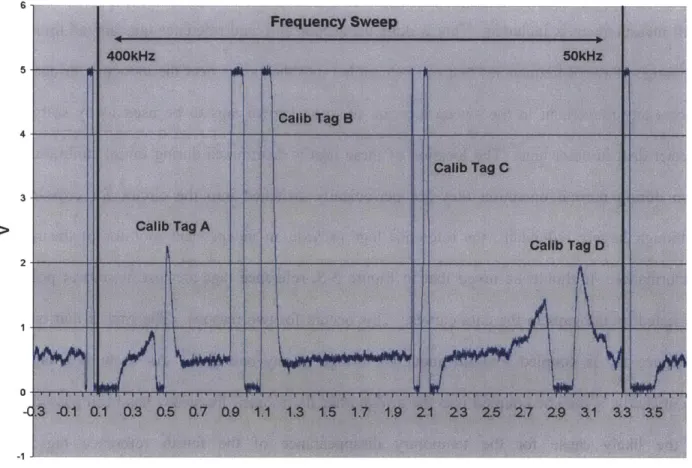
performance. It should be noted that in Figure 3-5, reference tags are lost at several points, as
indicated by the gaps in the data curves. This occurs for two reasons. The first is that only one
reference tag is coupled into the inductive bridge at any one time. As such, if a tag drifts
significantly, it may be coupled into the bridge after its resonant frequency has been passed. This
is the likely cause for the temporary disappearance of the fourth reference tag in the
uncompensated half of Figure 3-5. This difficulty can be corrected by altering the control to switch
a reference tag in for an entire sweep rather having all four tags share only one. The second reason
a tag may fail is due to the discrepancies between coupling strength. As these resonance tags
connect directly into the inductive bridge, they can couple extremely strongly. Consequently,
finding tags that do not couple overwhelmingly can be difficult. As a result, as shown in
Figure3-6, the outside two tags couple far less than the inside tags and actually have a small enough
magnitude that they could be lost due to noise combined with the high software threshold attached
to calibration tags. This imbalance could be addressed by coupling the calibration tags via an
these tags are coupling in an inverted fashion as they are coupled into the opposite leg of the
bridge.
0--c
Time (msec)
Figure 3-6: Sweep Output with Calibration Tags
One last note about frequency drift compensation methods and the sampling of the baseline
is that in order to get initial values, the tag reader must start out in a calibration state. Upon
initializing the board, the user can set the board in a halted mode, where the drivers will run, but the
board will not be processing the data. This is to allow the user to manually tune the board without
having the board try to automatically counteract any changes in the sweep. Once the board has
been tuned, the user flips a switch and the board will perform initial calibrations. In order to get a
these have occurred, the board must also place the calibration tags. The final result is that the
board now takes roughly a minute after being lifted from the halt state before it is ready to start
processing tag interactions.
3.4 Alterations to Inductive Sensing Circuitry
The third functional area of the board, the inductive sensing, has also been modified in
order to take full advantage of the sensitivity and baselining now provided. Without a fixed
baseline and with a less sensitive A/D, the earlier board required more analog gain. This is no
longer necessary. As such, rather than using 6 amplifiers, the new board needs only 4 to achieve
improved sensitivity and much wider dynamic range.
There is one other addition to the board, namely the addition of multi-axis capability to
resolve larger areas and spatial coordinates. One of the truly interesting regions for exploration
with the tag reader is developing multi-coil geometries. Depending on the geometry, this often
involves cycling through multiple drives. A six-coil cube geometry was built previously[1] that
used one frequency sweep that would be cycled across three pairs of coils to make a more uniform
field successively spanning three orthogonal axes. This means only two coils were driven at any
time. The implementation of this system was done by using 6 complete tag readers with frequency
sweeps disconnected from the final amplification and bridge stages. The frequency sweep from the
master board was then cycled by programmable switch to drive the disconnected amplification and
sensing. The final detected output from each board was then routed through an analog multiplexer
Figure 3-7: Old 6 Coil Tag Reader
As seen in Figure 3-7, this implementation is not only very large and ungainly, but also well
over 1/3 of the circuitry is redundant or never even used. In order to enable the creation of a more
compact multi-coil reader and also reduce repetitive circuitry, the new tag board is capable of
running up to three coils non-concurrently. The tag reader uses a fast, high-current MAX352 IC
precision analog switch to pass the completed frequency drive to one of three inductive bridges.
This removes all redundancy within the frequency sweep generation and drive mechanism and
means that all three coils are guaranteed to be driven by the same signal. As outlined in Figure 3-2, the three signals are then switched back together through an analog multiplexer just prior to the last
gain stage . This provides for the output phase and gain of each coil to be individually set. The
one drawback is that the MAX352 analog switch is not entirely capable of handling the large
current draw at the low end of the frequency sweep. Under roughly 90kHz, there thus begins to be
a noticeable depreciation in drive signal. Lower frequency tags will still be detected but their
dynamic range may be slightly more limited. If running with just one coil, this can be avoided by
bypassing the MAX352. The end result is that without significant loss of capability, a six-coil
reader can now be built with just two boards instead of six, bringing the size of the six-coil reader
down from the size of a large desktop computer case (see Figure 3-7), to slightly more than a
Chapter 4
Early Tag Reader Applications
A number of applications have been developed using the swept frequency tag reader. They range from early simple interactions meant to demonstrate the bare functionality of the board to the
more conceptually complex most recent application Musical Navigatrics. Although the tag reader
has significant potential for usage outside the musical domain, the entire repertoire of applications
to date have had some significant sonic output although almost more by coincidence than design.
The earliest application for the tag reader was implemented by placing the coil beneath a
Lego board and embedding tags into Lego blocks[l]. Each tag had a corresponding tone that would be generated if the tag was placed into the reader's magnetic field. This implementation
provided for a very basic demonstration of the tag reader's capability to sense and distinguish
between tags. More complex interactions were also introduced by adding a multi-tag object and a variable frequency tag. The multi-tag object used three LC tags placed orthogonal to each other to
determine the orientation of the object. This works because the magnitude of response to a tag is proportional to both distance and orientation. As the object rotates, different tags are rotated
perpendicular to the magnetic field, changing the relative signal strength between the three tags.
The variable frequency tag consisted of a magnetostrictor with a small magnet behind it. Moving the magnet would produce a continuous, detectable change in the response frequency.
4.1 Tangible Media and musicalBottles
Hiroshi Ishii and the Tangible Media Group at the MIT Media Lab have implemented a
second application. Their work has involved the idea of taking the everyday inert physical object
and introducing digital meaning into it while retaining the object's conceptual model. Tangible
Media's application is a bottle that releases atypical contents when the bottle's stopper is removed
and the bottle is opened. The project has explored a number of "contents" and interactions
beginning with musicalBottles[6] and later bottlogues[7] and genieBottles[8]. Each
implementation consists of three bottles placed on a table that doubles as a tag reader. With
musicalBottles, opening the bottles will play one of the three lines (piano, violin, or cello) from
Edouard Lalo's "Piano Trio in C minor, Op.7, while opening a bottle in bottlogues releases a single
character's part in a three person narrative. GenieBottles controls the intertwining stories of three
genies trapped in their bottles. Each interaction explores the physical nature of the bottles as a
container and the digital controls created by them, letting the user realize the seeming impossibility
of releasing sound from an opened bottle.
Figure 4-1: Tangible Media Group's musicalBottles
MusicalBottles and its successors all use the tag reader in the same hardware setup. In
stopper has a ferrite core embedded into it while the bottleneck has coil wrapped around it. Thus, removing the cork (and with it the ferrite core), the bottle's tag is detuned. This is then detected by
the tag-reader and passed on to a computer that interprets the data and uses a state machine to decide when to trigger the appropriate sound output.
4.2
Musical Trinkets
The third primary application, Musical Trickets [1][9][10], was done entirely by Kai-Yuh
Hsiao and Responsive Environments Group. It is also based on using music to demonstrate the tag
reader's capabilities. In Musical Trinkets, 20 tags have been placed in 16 objects, which then create
and modify a musical soundscape based on their behavior in the sensing field created by an search
coil connected to the tag reader and set into a table. The musical interaction is built around a set of
melodic musical tones and a harmonic progression, with additional musical effects that modify and
add to these tones and harmonies. The "trinkets" themselves are predominantly Halloween toys, with the result that the interactive objects ended up being mostly ghosts and goblins and a random
assortment of other small toys, all embedded with tags. The main music generation tags are the
ghost rings and the goblins. These trigger the musical tones and harmonies. The 5 ghost rings are
worn on the fingers while the hand is held over a sense table with the search coil set in it. As the
fingers are bent, the rings change orientation and become aligned to the sense field, thus triggering
individual musical notes. It is somewhat similar to playing a piano. The goblins, meanwhile,
control the harmonies. Individually, each of the 3 goblins triggers a different chord. As additional
goblins are added or removed, Musical Trinkets uses a state table[1] to determine what chord is
Figure 4-2: Tagged Objects used in Musical Trinkets
When added to the sense field, a Pikachu will add a twinkling of semi-random notes. The
pitch region of this twinkle is determined by a Pikachu's proximity to the sense table. A pig
modifies the musical lines by adding vibrato proportional to proximity, while a dinosaur with a
magnetostrictor instead of an LC tag acts as a switch, triggering a change in the lines' instrumental
voices. A foot provides continuous pitch bend and discrete transposition based on proximity to the
sense coil.
There are also more complex interactions with specially tagged objects. As in the initial
Lego experimentation[ 1], there is a cube and now also an eyeball, each with three perpendicular
tags from which to track distance and orientation. The cube is used to add and bend a low droning
voice, while the eyeball provides a particularly interesting interface as the tags coordinate to
control various parameters on a Lexicon effects synthesizer. Lastly, a variable tag once again
appears, this time as a Pez candy dispenser which fades in a choral sound based on proximity and
achieved by pulling up on the Pez dispenser head, which moves a ferrite core placed through a coil
in order to chance the inductance of the tag. A cone can be used as a switch to change the Pez
instrumental voicing.
Musical Trinkets has been shown at a number of conferences[9][11][12] and demos around the world to thousands of people. General response is very positive, surely due in part to relatively
clear and easy to understand interactions, as well as an enjoyable and unique interface. However,
Musical Trinkets is, as the name suggests, a fairly trivial musical interaction. Although it serves its purpose well as a demonstration tool for the tag board, the tagging interface, and the potential of
tags as a musical controller for both solo and group improvisations, it lacks significant substance.
It is limited in its usefulness for the real creation of complex music. Also, while some of the tags, for instance the effect-introducing eyeball, do make clear use of the continuous real-time capability
of the tag interface, the exploration of the continuous nature is generally limited and fails to deeply
explore and make strong use of the sound controlling potential that exists.
The data used to generate the sound controls in Musical Trinkets is also used to produce
pleasant interactive graphics using OpenGL[1]. The graphics are projected from beneath a table
onto a piece of translucent plastic that forms the table top inside of the coil. This provides for
direct graphical user feedback. The graphics can also be rerouted for display on a bigger screen or
other surface. They are generally coordinated to match either the physical aspect or the sound
aspect of an object. For instance, rolling the eyeball around the table triggers the graphic of an
eyeball rolling around the table, with the graphic rotating based on the actual rotation of the real
eyeball object.
The initial graphic consists of a flat gray disk on a black background. Adding tags will
Figure 4-3: Multi-user Interaction with the Musical Trinkets
musical tools, the ghost rings and the goblins generate bouncing colored balls and fade in
individual colored spotlight-like triangles, respectively. The Pikachu adds swirling diamonds that
spin around the disk, while the pig causes the bouncing balls from the ring to shimmer
complementing the vibrato it adds aurally. The dinosaur flips the disk over, and the foot changes
the perspective, essentially zooming in or out. The eyeball adds a graphical eyeball that rotates
along with the real one. The cube presents probably the most interesting graphical response. As
the cube is turned and flipped, the entire graphic rotates and flips along with it. The graphics
associated with tags such as this provide a clear indication of the tag reader's abilities to determine
orientation. Of the remaining two tags, the Pez tag adds a blue ring to the gray disk and a second
violet disk when detuned. Lastly, in some variations of Musical Trinkets, the cone acts as a
music-responsive graphic developed by Marc Downie from the synthetic characters group at the MIT
Media Lab[13].
Chapter
5
Musical Navigatrics
Musical Navigatrics is the most recent and most complex application developed for the tag
reader. It was designed by the author an attempt to create a comprehensive and exciting musical
instrument using the tag reader, and in the process explore the various potentials of the tag reader
as an expressive musical interface. It is the next step beyond Musical Trinkets, adding depth and
musical creativity. There are three conceptual areas that Musical Navigatrics explores: using the
tag reader to implement a free space musical instrument, its functionality as an effects controller,
and adaptability of the discrete nature of moving tags in and out of the magnetic field to develop a
basic sequencer, enabling complex tracks to be recorded, overdubbed, modified and accessed
during performance. These areas provide the foundation for the three main components required to
build an expressive song: notes, timbre, and order. The ability to combine these three musical
aspects together provides for a large amount of musical potential and depth, as well as real
practicality towards developing and composing a performance. All mappings of tags to music are
thus geared to give full musical flexibility to the user within the limits of musical hardware and
software as well as the tag reader itself. Considering the fact that most of the time, for meaningful
musical production, Musical Navigatrics would be played by one, possibly two people, each with
only two hands available for manipulating objects, mappings were chosen to enable as much
control as possible considering that generally only one or two tags may be giving dynamic input at
allows the development of multiple voices as well as the addition of effects on top of already
played lines. The choices of sounds and effects were also selected to provide for the most
interesting but also discernable range of output. The end product is a substantial expansion of Musical Trinkets into a musical instrument and expressive free-space means of musical production.
Figure 5-1: Musical Navigatrics Setup
5.1 Technical Implementation
In starting the new application, it was decided to move away from implementing MIDI
mappings using C++ and Rogus[14] and instead use a more powerful, better supported program
that is more directed towards musical applications. MA4X[ 15] describes itself as "a graphical music
programming environment for people who have hit the limits of the usual sequencer and voicing programs for MIDI equipment."
This describes just what was needed for the task. MAX provides for simplified MIDI
mapping. However MAX is currently written only for the Apple Macintosh platform and while
Macintosh's are generally very good for music applications, they lack non-USB serial support. The
current tag reader only outputs data on a DB9 serial cable. It is, however, easy to route MIDI to a
Macintosh using one of the many MIDI-USB adapters. Thus the MIDI stream for MAX is
produced by taking the serial data produced by the tag board used with the tagged objects from
Musical Trinkets and processing the data using a modified version of Kai-Yuh Hsiao's earlier PC
based Musical Trinkets application. As the original Musical Trinkets was already generating MIDI
signals using the tag reader, it was fairly simple to adapt it to pack the information regarding
present tags and their signal strengths into MIDI data. The MIDI stream is then sent to a Unitor
MIDI interfaces, as also used in Musical Trinkets, which distributes it to the MIDI input for MAIX,
in this case, a MIDIMAN MIDISPORT 4 connected to an Apple G4 Cube.
In Musical Navigatrics the modified Musical Trinkets program sends MIDI notes via a
MIDIMAN. The MIDI values are reassigned, however, so that each MIDI note value corresponds to the presence of a different tag, while the note velocity relates to the signal strength. This
standard tag information is sent on MIDI channel 0. Channel 1 is used to relay any additional
tagging information, which at present is restricted to the variable-frequency Pez tag. For this tag,
its overall presence and strength is still sent via channel 0, but a corresponding note value on
channel 1 is used to relay any shift in the tags frequency.
Once the MIDI data has been received by MAX, it is translated and remapped to run the
music production side of Musical Navigatrics. At present, there are two versions of Musical
Navigatrics. These two versions are functionally the same, only they use different sound
synthesizers. Musical notes were produced using an EMU Proteus 2000 Sound Module while
effects were handled either by the EMU or a Lexicon MPX-100 Dual Channel Effects Processor.
All sequencing was implemented from scratch in M4X using the MAX seq function for actual
recording.
Version II removes the need for sound generation hardware by using Propellerheads Reason
software[ 16] for sound production. MIDI messages, both note and control, from MAX are
internally passed to Reason, which redirects them among its various virtual rack devices.
Additionally, all prerecorded sequences, such as drum loops and neutral figuration, are created and
handled within Reason. Real-time sequencing and sequence coordination is still being performed
in MAX.
5.2
Musical Implementation
Like the three conceptual areas of Musical Navigatrics, the tags themselves were divided up
into 3 corresponding categories: note production tags, expressive effects tags, and control tags.
Note tags are any tags that trigger a sound. Effects tags are used to modify the note voices and the
control tags are used to store information about the movement of the note and effect tags.
Note Tags: There are 5 note tags. The first three (the red goblin, the green goblin, and the blue
goblin play) respectively, a soprano voice, a tenor voice, and a bass voice. The note played
corresponds to the signal strength of the tag, so that the tag's distance from the table more-or-less
decides the played note. Moving the tag up and down vertically over the table will step through a
discrete C Major scale. The farther the tag is from the table, the higher the note produced. All the
octave up, or the V below C (G) to the D an octave up. These ranges, though somewhat small,
were chosen to take the best advantage of the available dynamic range; allowing the user to pick
from a
Record Record Line Line
Direct (No "Play" ("Play" Play Effects? Effects?
Tag Behavior Sound present or and voice (Voice (Other (No Master
In Field Produced voice not already already Voices voices Effects
recorded) recorded) recorded) Active) active)
. Not Present None No Action Action Action No Yes Yes
. Current Current Current Current Yes
Action Action Action Action
> On table None No Action Prev Prev Yes Yes Yes
Action Action
. Prev Prev Yes
Not Present None No Action Action Action No Yes
Active Current Current Current Current Yes Yes Yes
.2 Action Action Action Action
On Table Max Value Max Value Prey Prey Yes Yes Yes
Action Action
Figure 5-2: Voice Tag Interactions
"Action "is defined as any movement within the sense field and an "active" tag is any tag within the field not sitting on the sense table. The first record category refers to when there is no Play Pikachu present or, if it is, the voice has not already been recorded. The second record category refers to both the Play Pikachu being present and the voice having been recorded. The effects categories refer to whether an effect will be heard on that voice or not.
useful range of notes while not packing so many notes into the sense region that it becomes
difficult to locate a particular note. Thus, the blue goblin playing the bass voice also offers a 5 note
range, C to the V above (G), as the tag is not as strong as the others and has a reduced dynamic
range. Bass voices traditionally jump around the scale less, so this is also somewhat appropriate.
Lastly, due to the fact that the field strength is non-linear with positioin, the mappings are written
to help linearize the playing region, as this makes a more intuitive interaction. This weighting, as
well as the notes out, can be seen in Figure 5-3 the MAX note mappings. One last aspect of the
---Di
Bass Note
Selection
select range
this gives you a this gives a weitedd
major scale with 12 c major seal It ait thi giver sae wigted
note range with 8 notes only 5 notes
- each rwesonts 6
Figure 5-3: MAXNote Tables for Note Determination
Basic Note Selection
tag "velocity" t -A r MIDI note c - 60 J select range
his gives a c major this gives a c major
oa I& with 12 note scale with weighted
ange 8
note rangeeah0rpsnt
In Figure 5-2, there is no note mapping for a goblin sitting on the table as this state is used to select
a voice for line effects. This will be further explained in the section on line effects.
Figure 5-4: Note Tags
The other two note tags are less strictly notes, as there is not quite the same distance-to-note
correlation. However, they functionally act as note tags, in that they trigger new sounds, can be
recorded by the sequencer, and can be modified by the effects tags. The first is the dinosaur.
Moving the dinosaur into the tag-reading field triggers a predominantly pre-recorded drum pattern.
In order to provide the user with more than one drumbeat, the dinosaur takes advantage of the
dynamic range of the signal strength provided by its proximity to the coil to select different
rhythms. The closer the dinosaur is to the coil, the generally more aggressive and dense the rhythm
played. There are seven different pre-recorded rhythms to choose from, with a variable number of
The last note tag is the Pez dispenser. It controls either a chord or neutral figuration. When
initially placed into the tagging field, it will play triad C-Major scale chords. As in Musical
Trinkets, the Pez dispenser is a variable tag, so that raising the Pez head will turn off the chords and
instead step through a selection of 4 pre-recorded neutral figurations with each additional head
raising. Moving the Pez dispenser vertically over the tagging field table changes the chord or
transposes the figuration. This time there are 8 possible chords/transpositions ranging from C
Major to C major, but the order is reversed from the goblin voice tags, so that sitting the tag on the
table will trigger the highest chord instead of the lowest. This allows triggering of the low C chord
upon removal, a more typical progression than the other way around. Along with this, the chords
are weighted so that the more common chords, such as I, IV, V, VI and I octave, have a large
playing region and are easier to hit than less useful chords like III.
Figure 5-5: Effects Tags
and master effects, based on their scope. Regardless of their function, line effects are able to act
upon and modify any given note tag or selection of note tags. Master effects meanwhile are more
limited in scope to act on every tag or a specific non-changeable set of tags. While effects tags can
be played and even recorded independently, they require a note tag or already recorded note-tag
sequence to be heard.
Line effect tags control effects where the user can choose one or more note lines and control
the sound of just that line alone. A line is easily selected by placing the corresponding tag into the
tag field. As discussed in the section on note tags, placing a voice tag on the sense table will select
it for line effects and will not actually play new notes. This is particularly useful when playing
back recorded lines, as it allows a recorded voice to be selected for effects without playing over the
recorded line. For instance, when Musical Navigatrics is playing back a sequence composed of a
bass voice line and a high voice line, if the red goblin high voice is placed on the table, any line
effect introduced to the sense field will operate only on the high voice. However as any tag
dynamically present in the sense field receives effects, if the same line is played back with the red
goblin still on the table but this time the green goblin middle voice is being actively played, the
effect tag will now be applied to both the red and green goblins' corresponding voices.
Both the Pez figuration tag and the dinosaur drums can be selected in the same way for
effects, but unlike the voice tags, they have no passive select state and will always play based on
their proximity. If all note tags or no note tags are present in the sense field, line effects will
operate on all note lines.
The available line effects are: filter cutoff frequency, filter resonance frequency, transpose
and volume. Cutoff frequency and resonance are mapped onto the black ring and the red ring
controlled by the signal strength of the coupling between the tag and the coil. As the tags
themselves are rings, they are not expected to be used in quite the same perpendicular up-down
manner as many of the other tags. A more common mode of interaction is to wear the rings. The
result is that the effect magnitude changes not only with distance from the sense table, but also
changes as the hand moves and rotates through the field. Wearing multiple effects rings (there are
also two master effects rings) triggers musical response to the shape of the hand and its full
movement through space.
The Transpose Foot will transpose all selected voices (with the understandable exception of
the unpitched dinosaur drums) up in relation to the C Major scale. There is no transposition when
the foot is sitting on the sense table, but as soon as it is raised, it will move selected voices as much
as a full octave. This provides the user the opportunity to introduce easy additional chord
structuring. The Volume Cone unsurprisingly acts to control the volume of a voice. As an
extension, the Volume Cone also acts as the mute cone. When the cone is placed on the sense
table, it will mute all selected voices and slowly return them as it is removed from the from the
sense field.
For the most part, master effects are effects that, due to the hardware or software
implementation at the point of sound generation, are only available to act on all sounds. This is
true for 3 of the 4 effects: the cube, delay ring and the distortion ring. The eyeball, on the other
hand, rotates a set of effects through the three primary voices. Regardless of the actual effect,
however, they are unable to act independently on one voice and thus are considered master effects.
As a shown in Figure 5-2, unlike line effects, it makes no difference to the sound output what other
Apart from their region of effect, the delay and distortion rings act much like the resonance
and cutoff rings. The signal strength from the tags in the rings is simply passed on as a MIDI
control signal and sent to the relevant device to add delay or distortion. The cube and the eyeball
have much more fun and unpredictable effects. Again, as in Musical Trinkets, both of these two
objects is embedded with three perpendicular tags. The cube uses its three axes to control three
separate parameters of the attached Lexicon effects processor, adjust, mix, and effects level. In
Version II, the cube alters panning as well as phasing and compression. The eyeball, rather than
using the three tags to produce effects in coordination with each other, links each of its three tags to
one of the three primary goblin voices and sends a set of effects to each voice based on how much
its tag couples. As the eyeball rotates and rolls around the table, effects essentially rotate through
the voices, altering one or two to voices at a time. The eyeball triggers a variety of effects: slight
pitch modulation, decay modification and alteration of one of the filter envelopes. In Reason it
once again causes slight pitch modulation, but this time also adds distortion and alters filter
modulation. Regardless of the software version, the eyeball ends up creating a somewhat
unpredictable but highly intriguing interaction.
Control Tags: Control tags run the sequencing capabilities of Musical Navigatrics. There are only three control tags, Play Pikachu, Record Pig, and the Tempo Ring, but they dramatically impact the
usefulness and depth of Musical Navigatrics by letting the user move beyond controlling one or
two aspects of musical creation and instead offering a whole realm of sound possibilities. The
Record Pig and the Play Pikachu are the only two tags for which there is a simple on/off state.