Development of a High Power Density Combustion System for a
Silicon Micro Gas Turbine Engine
by
Amitav Mehra
B.S., Engineering and Applied Science, California Institute of Technology, (June 1995) S.M., Aeronautics and Astronautics, Massachusetts Institute of Technology, (June 1997)
Submitted to the Department of Aeronautics and Astronautics in partial fulfillment of the requirements for the degree of
Doctor of Philosophy
at the
Massachusetts Institute of Technology
February 2000
@ Massachusetts Institute of Technology. All rights reserved.
Author
/
Department of Aeronautics and Astronautics January 26, 2000
Professor Ian A. Waitz
Associate Professor of A iftics and Astronautics, Committee Chairman
Professor Alan H. Epstein R. C. Mclaurin Professor of Aeronautics and Astronautics
Professor Jack L. Kerrebrock Professor of Aeronautics and Astronautics, Emeritus
Professor Nesbitt W. Hagood Associate Professor of Aeronautics and Astronautics
SSACHUSETTS ISTITUTE Chairman, Department Graduate Committee
SEP 0
7
2000
Certified by Certified by Certified by Accepted by MADevelopment of a High Power Density Combustion System for a Silicon Micro
Gas Turbine Engine
by
Amitav Mehra
Submitted to the Department of Aeronautics and Astronautics on January 26, 2000,
in partial fulfillment of the requirements for the degree of Doctor of Philosophy
Abstract
As part of an effort to develop a microfabricated gas turbine engine capable of providing 10-50 Watts of electrical power in a package less than one cubic centimeter in volume, this thesis presents the design, fabri-cation, packaging and testing of the first combustion system for a silicon micro heat engine. The design and operation of a microcombustor is fundamentally limited by the chemical reaction times of the fuel, by sili-con material and fabrication sili-constraints, and by the inherently non-adiabatic nature of the operating space. This differs from the design of a modern macrocombustion system that is typically driven by emissions, stability, durability and pattern factor requirements. The combustor developed herein is shown to operate at a power density level that is at least an order of magnitude higher than that of any other power-MEMS
device (2000 MW/m 3), and establishes the viability of using high power density, silicon-based combustion
systems for heat engine applications at the micro-scale.
This thesis presents the development of two specific devices - the first device is a 3-wafer level
microcombus-tor that established the viability of non-premixed hydrogen-air combustion in a volume as small as 0.066 cm3,
and within the structural constraints of silicon; the second device is known as the engine "static-structure", and integrated the 3-stack microcombustor with the other non-rotating components of the engine. Fabri-cated by aligned fusion bonding of 6 silicon wafers, the static structure measures 2.1 cm x 2.1 cm x 0.38 cm, and was largely fabricated by deep reactive ion etching through a total thickness of 3,800 pm. Packaged with a set of fuel plenums, pressure ports, fuel injectors, igniters, fluidic interconnects, and compressor and turbine static airfoils, this structure is the first demonstration of the complete hot flow path of a multi-level
microengine. The 0.195 cm3 combustion chamber has been tested for several tens of hours and is shown
to sustain stable hydrogen combustion with exit gas temperatures above 1600K and combustor efficiencies as high as 95%. The structure also serves as the first experimental demonstration of hydrocarbon
micro-combustion with power density levels of 500 MW/m 3 and 140 MW/m3 for ethylene-air and propane-air
combustion, respectively.
In addition to the development of the two combustion devices, this thesis also presents simple analyti-cal models to identify and explain the primary drivers of combustion phenomena at the micro-sanalyti-cale. The chemical efficiency of the combustor is shown to have a strong correlation with the Damkohler number in the
chamber, and asymptotes to unity for sufficiently large values of Da. The maximum power density of the
combustor is also shown to be primarily limited by the structural and fabrication constraints of the material. Overall, this thesis synthesizes experimental and computational results to propose a simple design method-ology for microcombustion devices, and to present design recommendations for future microcombustor development. Combined with parallel efforts to develop thin-film igniters and temperature sensors for the engine, it serves as the first experimental demonstration of the design, fabrication, packaging and operation of a silicon-based combustion system for power generation applications at the micro-scale.
Thesis Supervisor: Professor Ian A. Waitz
Acknowledgments
I would like to thank Professor Ian Waitz for his valuable guidance and direction throughout the course of this research. I also wish to express my sincere gratitude to Professor Alan Epstein for his guidance, and for being a great teacher and mentor; to Professor Jack Kerrebrock for his invaluable advisory role; to Professor Stephen Senturia for his insightful suggestions during the igniter study, and to Dr. Choon Tan for his encouragement throughout my Masters and Ph.D. research.
Along with all the other members of the MIT microengine team, I wish to express special thanks to Dr. Arturo Ay6n for his help with the fabrication process, to Dr. Xin Zhang for spending painfully long hours in front of the STS during the fabrication of the last two builds of the static structure, and to Professor Mark Spearing, Dr. Stuart Jacobson, Dr. Eugene Huang, Jin-Wook Lee, Dr. Chris Cadou, Chris Spadaccini, Steve Lukachko, Todd Harrison and Sumita Pennathur for their help along the different design and analyses stages of the combustion devices.
I would also like to express my gratitude to Mr. Gregory Simpson at Thunderline-Z for his personal
dedication and creativity in coming up with packaging solutions for my combustor.. .Thanks Greg -without
you I'd probably still be messing around with epoxy!!!
I am also grateful to Viktor Dubrowski for machining countless little "widgets" for me, and to Bill Ames and Jimmy Letendre for facilitating my experimentation efforts. Thanks to Diana Park as well for converting all my mask sets into pretty 3-D schematics, and for all the additional help with the figures.
In addition to the above people who have helped me with my research efforts, I am especially thankful
to all those who have helped make my stay here at the GTL a pleasant one... .Lori -thanks for being a great
friend and taking care of all of us grad. students; Luc, Zolti, Adam, Rory, and Erik -thanks guys, couldn't
have done it without your help and friendship!!
Finally, I'd like to thank my family -my brother and sister-in-law for their encouragement; my
grand-parents, who gave me more love than I could ever hope for; and my mom and dad, to whom I will always owe every bit of my success and happiness.
This work was sponsored by the United States Army Research Office, Drs. R. Paur and T. Doligalski, technical managers, and by DARPA, Drs. R. Nowak, D. Fields and S. Wilson, program managers. Their support is gratefully acknowledged.
Contents
1 Introduction 23
1.1 Background ... ... ... 23
1.2 The MIT Microengine . . . . 24
1.2.1 Baseline D esign . . . . 24
1.2.2 Component Requirements and Technologies . . . . 25
1.3 Microcombustor Design Considerations . . . . 26
1.4 Review of Previous Research . . . . 28
1.4.1 MIT Microengine Combustor Research . . . . 28
1.4.2 Silicon Power-MEMS . . . . 28
1.4.3 Macrocombustion Systems . . . . 30
1.5 Development Approach . . . . 30
1.6 Contributions of the Research . . . . 32
1.7 Organization of the Thesis . . . . 32
2 Microcombustor Design Issues 35 2.1 Introduction . . . . 35
2.2 Functional Requirements . . . . 35
2.2.1 General Combustion Systems . . . . 35
2.2.2 Microengine Combustor . . . . 36
2.3 Primary Design Challenges . . . . 36
2.3.1 Residence Time Constraints for a High Power Density Device . . . . 36
2.3.2 Materials and Fabrication Constraints . . . . 38
2.3.3 Heat Transfer Constraints . . . . 39
2.3.4 Other Challenges . . . . 40
2.4 Combustor Design Philosophy and Approach . . . . 41
3 Development of the Engine Combustor 3.1 Introduction ...
3.2 Goals of the Silicon Microcombustor . . . .
3.3 Design of the Silicon Microcombustor . . . .
3.4 Fabrication of the Silicon Microcombustor . . . .
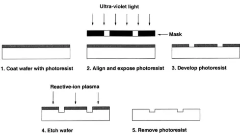
3.4.1 Photolithography . . . .
3.4.2 Deep Reactive Ion Etching . . . .
3.4.3 Aligned Wafer Bonding . . . .
3.5 Experimental Testing . . . .
3.5.1 Experimental Apparatus . . . .
3.5.2 Experimental Diagnostics . . . ..
3.5.3 Hydrogen Test Results . . . .
3.5.4 Hydrocarbon Test Results . . . .
3.5.5 Repeatability of the Results . . . .
3.6 Materials and Oxidation Testing . . . .
3.6.1 Atmospheric-Pressure Oxidation Tests . . . . .
3.6.2 High Pressure Oxidation Tests . . . .
3.6.3 Turbine Vane Oxidation Tests . . . .
3.7 Overall Implications and Chapter Summary . . . . 4 Development of the Engine Static Structure
4.1 Goals of the Engine Static Structure . . . .
4.2 Development Plan . . . . 4.3 Design of the Engine Static Structure . . . .
4.3.1 Overall Configuration . . . .
4.3.2 Design of the Fuel Injectors . . . .
4.3.3 Design of the Flame Holders . . . .
4.3.4 Turbomachinery Stator Blade Design . . . .
4.3.5 Structural and Thermal Design . . . .
4.3.6 Diagnostics . . . .
4.3.7 Igniter Design . . . .
4.4 Fabrication of the Engine Static Structure . . . .
4.5 Packaging . . . .
4.5.1 Fluidic Interconnects . . . .
4.5.2 Electrical Interconnects - Integrated Igniters
4.6 Experimental Testing . . . . 4.6.1 Experimental Objectives . . . . 8 43 43 43 44 46 49 49 49 50 50 50 51 56 58 58 58 60 60 62 65 . . . . 6 5 . . . . 6 6 . . . . 6 6 . . . . 6 7 . . . . 6 9 . . . . 7 4 . . . . 7 4 . . . . 7 6 . . . . 7 6 . . . . 7 8 . . . . 7 8 . . . . 8 2 . . . . 8 2 . . . . 8 7 . . . . 8 8 88
4.6.2 Experimental Apparatus and Diagnostics . . . .
4.6.3 Cold-Flow Tests . . . .
4.6.4 Baseline Device Characterization (Hydrogen Tests) . . . . 4.6.5 Empirical Identification of the Microcombustor Operating Space 4.6.6 Hydrocarbon Tests . . . .
4.6.7 Repeatability of the Test Results . . . .
4.7 Chapter Summary . . . .
5 Development of Interconnects, Igniters and Temperature Sensors
. . . . 89 . . . . 89 . . . . 94 . . . . 108 . . . . 108 . . . . 110 . . . . 114 117 5.1 Introduction . . . . 117
5.2 Requirements for On-Chip Igniters and Temperature Sensors . . . . 117
5.3 Design of the Thin Film Resistors . . . . 118
5.4 Development of A Novel Interconnect Scheme . . . . 120
5.5 Fabrication of the Thin Film Resistors and Interconnects . . . . 120
5.6 Experimental Test Results . . . . 122
5.6.1 Isolated Igniter Test Results . . . . 123
5.6.2 Evaluation of the Ignition Capability . . . . 125
5.6.3 Thermal Modeling of the Igniters . . . . 125
5.6.4 Material Integrity and Polysilicon Degradation . . . . 127
5.6.5 Temperature Sensor Test Results . . . . 132
5.6.6 Determination of a Stable Temperature Regime for Polysilicon . . . . 134
5.7 Recommendations for Design Improvements . . . . 137
5.7.1 Igniters . . . . 137
5.7.2 Temperature Sensors . . . . 138
5.7.3 Through-Wafer Interconnects . . . . 139
5.8 Chapter Summary . . . . 139
6 Implications for the Design of a Microcombustor
6.1 Assessment of the Design Methodology . . . .
6.1.1 Validation of the CFD Tools . . . .
6.1.2 Validation of the Heat Transfer/Structural Model . . . . 6.1.3 Role of Conjugate Reacting-Flow, Heat Transfer CFD . . . . . 6.1.4 A Simple Damkohler Number Based Design Methodology . . . 6.1.5 Design Guidelines, Methodology for Microcombustion Systems 6.1.6 Utility of the Model - Thought Experiments . . . . 6.2 Implications, Design Recommendations for the MIT Microcombustor . 6.3 Re-Examining the Primary Drivers for Microcombustion Systems . . .
141 141 141 143 144 145 146 148 149 151
6.4 Chapter Summary
7 Conclusions 157
7.1 Summary of the Research . . . . 157
7.2 Contributions of the Work . . . . 158
7.3 Recommendations for Future Work . . . . 161
A Uncertainty Analysis 163 A.1 Uncertainty in the Independent Measurements . . . . 163
A.1.1 Mass Flow Measurements . . . . 163
A.1.2 Pressure Measurements . . . . 164
A.1.3 Temperature Measurements . . . . 164
A.2 Uncertainty in the Derived Quantities . . . . 164
A.2.1 Equivalence Ratio . . . . 164
A.2.2 Combustor Static Pressure Ratio . . . . 165
A.2.3 Combustor Total Pressure Ratio . . . . 165
A.2.4 Corrected Wall Temperature . . . . 166
A.2.5 Corrected Exit Gas Static Temperature . . . . 166
A.2.6 Corrected Exit Gas Total Temperature . . . . 170
A.2.7 Combustor Efficiency . . . . 171
A.2.8 Thermal Efficiency . . . . 171
A.2.9 Chemical Efficiency . . . . 173
A.3 Summary . . . . 173
B Numerical Models for the Silicon Oxidation Study 175 B.1 Oxidation Model . . . . 175
B.2 Heat Transfer Model . . . . 177
B.2.1 Description of the Model . . . . 177
B.2.2 Comparison with Experimental Results . . . . 178
B.3 Summary . . . . 179
C Combustor-Inlet Design Models 181 C.1 Introduction . . . . 181
C.2 Design of the Combustor Inlet Slots . . . . 181
C.3 Sizing of the Annular Inlet . . . . 183
C.3.1 Description of the PSR Model. . . . . 184
C.3.2 Results for the Static Structure Combustor . . . . 184
C.4 Summary . . . . 186
10
D Structural
/
Heat Transfer Analysis for the Static Structure 187D.1 Description of the Model . . . . 187
D .2 R esults . . . . 188
D.2.1 Wafer Sizing ... ... 188
D.2.2 Evaluation of the Baseline Performance . . . . 188
D .3 Sum m ary . . . . 190
E Development of the Damkohler Number Model 191 E .1 A pproach . . . . 191
E.2 Estimation of the Residence Time . . . . 192
E.3 Validity of a 1-Step Reaction Model . . . . 193
E.4 Calculation of the Reaction Times . . . . 196
E.5 Implications for the Damkohler Number Model . . . . 201
List of Figures
1-1 Baseline design for the MIT micro gas turbine engine . . . . 25
1-2 Development approach for the microengine combustion system . . . . 31
2-1 Specific strength and stiffness for different materials . . . . 38
2-2 A comparison of the yield stresses of silicon, silicon carbide, and conventional superalloys . 39 3-1 SEM cross-section of the 3-stack microcombustor . . . . 44
3-2 An SEM of the combustion chamber from the 3-stack microcombustor . . . . 45
3-3 An SEM of the fuel plenum and fuel injector holes in the 3-stack microcombustor . . . . 46
3-4 An SEM of the second wafer in the 3-stack microcombustor . . . . 47
3-5 A schematic illustration of the process of photolithography and wafer etching . . . . 48
3-6 An illustration of the fabrication process for the 3-stack microcombustor . . . . 48
3-7 An wafer-level infra-red image of the double-bonded, 3-stack microcombustor . . . . 50
3-8 An exploded schematic of the microcombustor test rig . . . . 51
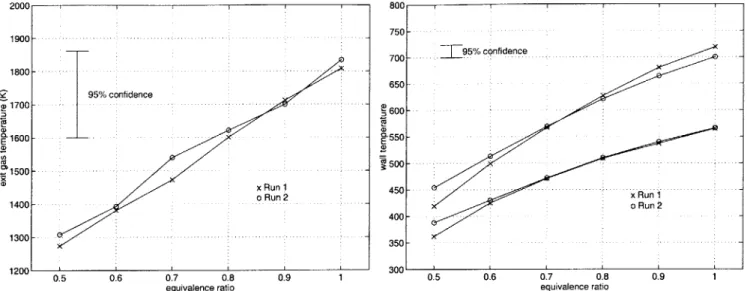
3-9 Experimental exit and wall temperature measurements in the 3-stack microcombustor . . . 52
3-10 Post-combustion examination of the microcombustor after high temperature operation . . . 53
3-11 Calculation of the efficiency for the 3-stack microcombustor . . . . 54
3-12 Estimates of chemical efficiency in the 3-stack microcombustor . . . . 56
3-13 Demonstration of propane combustion in a 0.2 cc silicon microcombustor . . . . 57
3-14 Repeatability of the experimental measurements . . . . 58
3-15 Experimental setup for the combustion oxidation tests . . . . 59
3-16 Oxidation results for the "fingered-combustor" geometry . . . . 59
3-17 SEM of the fingered-combustor showing creep limited behavior of silicon . . . . 60
3-18 SEM's of the fingered-combustor showing the different sized fingers that melted and failed due to creep . . . . 61
3-19 Experimental setup for the turbine vane oxidation tests . . . . 61
3-20 SEM and cross-section of the 4-wafer microcombustor and turbine NGV stack . . . . 62
4-1 Development approach for the microengine static structure 4-2 4-3 4-4 4-5 4-6 4-7 4-8 4-9 4-10 4-11 4-12 4-13 4-14 4-15 4-16 4-17 4-18 4-19 4-20 4-21 4-22 4-23
4-24 Pictures of the packaged static structure with one-step glass bead and brazed interconnects 4-25 Pictures of the fully-packaged static structure with mechanical and electrical igniter
inter-connects ... ...
Cold-flow test results for the static structure . . . . Results of the 2-D axisymmetric cold-flow CFD solutions. . . . .
A schematic illustration of the cold-flow at the exit of the static structure . . An illustrative explanation of the wrap-around phenomenon observed during testing of the static structure . . . . Cold-flow CFD solutions for the no-swirl and with-swirl case . . . .
Baseline performance characterization of the annular-inlet combustor . . . . . Estimates of res, Tch em and Da along a constant equivalence ratio curve . . . Efficiency along the
#=0.4
curve . . . . Results for the externally throttled combustor . . . .the cold-flow Schematic and SEM cross-section of the 6-wafer static structure . . . . Cold-flow CFD results for a 800 pm wide recirculation jacket . . . . Images of the 100 pm wide supports that bridged the recirculation jacket . . . . Images of the fuel plenums and injector holes in the static structure . . . . Schematic illustrations of the radial fuel injectors in the static structure . . . . Images of the radial fuel injectors in the fabricated static structure . . . . A schematic illustration of transverse fuel injection into a cross-flow . . . . SEM's of the two combustor inlet configurations in the static structure . . . . 2-D design and operating parameters for the compressor vanes in the static structure . . . . 2-D design and operating parameters for the NGV's in the static structure . . . . Pictures of the stationary turbomachinery blades in the static structure . . . . Wafer thicknesses and critical dimensions in the static structure . . . . An illustration of the placement of diagnostics in the static structure . . . . An illustration of the fabrication process for the static structure . . . . SEM's of the static structure wafers prior to bonding . . . . Optical image of the static structure along different axial planes . . . . Infra-red images of the bonded 6-wafer static structure . . . . SEM cross-section of the fully-bonded static structure . . . . Images of the ceramic epoxy setups used to test the static structure . . . . An illustration of the process used to make glass bead interconnects to the static structure Images of the static structure test rig with glass bead interconnects . . . . Images of the static structure with backside interconnects . . . .
14 66 67 70 70 71 72 72 73 75 75 76 77 77 78 79 81 82 83 84 84 85 85 86 87 88 90 91 92 93 93 95 96 98 99 4-26 4-27 4-28 4-29 4-30 4-31 4-32 4-33 4-34
4-35 Hot-flow total pressure measurements in the static structure . . . . 100
4-36 Baseline performance characterization of the slotted-inlet combustor . . . . 101
4-37 Comparison of the performance of the static structure with that of the 3-stack microcombustor102 4-38 Fuel injector performance at low mass flows . . . . 103
4-39 Investigation of upstream burning in the recirculation jacket . . . . 105
4-40 Cold-flow curves for four different samples after progressive high temperature exposure. . . 107
4-41 Experimentally measured operating space for the static structure . . . . 109
4-42 Experimental test results for ethylene-air combustion in the static structure . . . . 110
4-43 Experimental test results for propane-air combustion in the static structure . . . . 111
4-44 Repeatability of the cold-flow measurements . . . . 112
4-45 Repeatability of the temperature measurements and efficiency calculations . . . . 113
5-1 Fabrication process and images of the test igniters . . . . 119
5-2 An SEM and schematic representation of the through-wafer interconnect . . . . 120
5-3 Fabrication process and pictures of the test igniters and through-wafer interconnects . . . . 121
5-4 SEM's of conformal TEOS deposition in the igniter trenches . . . . 122
5-5 SEM's of a representative igniter . . . . 122
5-6 SEM's showing polysilicon deposition across different sized trenches . . . . 123
5-7 V-I and power-temperature curves for the test igniters . . . . 123
5-8 Infra-red and optical images of a heated igniter . . . . 124
5-9 Repeatability of the igniter test results . . . . 124
5-10 FEM grid and sample temperature distribution from the igniter thermal model. . . . . 126
5-11 Igniter surface temperature as a function of input power . . . . 127
5-12 SEM's of the igniters before and after electrical breakdown . . . . 128
5-13 Igniter V-I curves before and after exposure to combustion gases . . . . 128
5-14 SEM's of the resistors after 8 hours of exposure to combustion gases . . . . 129
5-15 SEM sample of an igniter before and after high temperature exposure in a furnace. . . . . . 130
5-16 Polysilicon surface roughness measurements after 6 hours at 1100*C. . . . . 131
5-17 SEM's of the igniters after progressive high temperature exposure in a furnace. . . . . 131
5-18 Linear fit to the resistance versus temperature data for the temperature sensor . . . . 132
5-19 Performance results for the on-chip thin-film temperature sensors . . . . 133
5-20 Increase in polysilicon room temperature resistance due to progressive high temperature exposure... ... ... 134
5-21 Room temperature resistance measurements of a pre-annealed polysilicon resistor after pro-gressive high temperature exposure . . . . 135
5-22 Stability of the polysilicon resistance during repeated anneals up to 450 C and 650 C. . . . 136
6-1 Comparison of the experimental cold-flow measurements with CFD solutions . . . .
6-2 Comparison of results from the heat transfer model with experimental measurements . . . .
6-3 Results from conjugate reacting flow CFD . . . .
6-4 Combustion efficiency versus Damkohler number for various operating points . . . .
6-5 Design methodology for microcombustors . . . . 6-6 Predictions of the residence time, reaction time and Damkohler number in the chamber . . 6-7 Predictions of the residence time, reaction time and Damkohler number for a dual zone
com bustor geom etry . . . . 6-8 Recirculation zone and streamline patterns in the 3-stack and 6-stack configuration . . . . . 6-9 Comparison of the performance of the annular and slotted inlet geometries . . . .
6-10 Streamline patterns from non-adiabatic solutions of the 3-stack and 6-stack geometries . . .
6-11 Comparison of the operating regimes for microcombustors and macrocombustion devices . . 6-12 Thermal efficiency of the 3-stack and 6-stack configurations . . . . B-1 Oxide thickness as predicted by the Deal-Grove thermal oxidation model for silicon . . . . . B-2 An illustration of the heat transfer model used to study the creep failure of the
fingered-com bustor . . . . B-3 Results of the heat transfer model used to study the creep failure of the fingered-combustor C-1
C-2 C-3 C-4 C-5
Schematic illustrations of the slotted-inlet configuration for the static structure . . . . Cold-flow solutions showing the flow propagating across the chamber as a 400 pm jet . . . . Jet spreading analysis used to size the combustor inlet slots . . . . Schematic illustrations of a perfectly stirred reactor . . . . Results from the PSR stability model . . . .
D-1 FEM grid, heat transfer coefficients, and temperature distribution in the static structure . D-2 Results of the FEM model showing sample stress distribution in the static structure . . .
E-1 E-2 E-3 E-4 E-5 E-6 E-7 E-8 E-9 142 143 145 147 147 149 150 152 153 154 154 155 176 177 178 181 182 183 184 185 189 190
Sample CFD solution, showing the temperature along different streamlines in the 6-stack . 192
Residence time estimates for the 3-stack . . . . 193
Residence time estimates for the 6-stack . . . . 194
Hydrogen mass fraction along the center streamline in the 3-stack . . . . 195
Hydrogen mass fraction along different streamlines in the 3-stack . . . . 197
Hydrogen mass fraction along the center streamline in the 6-stack . . . . 198
Hydrogen mass fraction along different streamlines in the 6-stack . . . . 199
Hydrogen mass fraction along streamlines in the 3-stack and 6-stack . . . . 200
Reaction time comparison for the 3-stack and 6-stack configurations . . . . 200
List of Tables
1.1 A comparison of the power density levels achieved by various devices . . . .
2.1 Comparison of the operating parameters for a microcombustor with those for a conventional
large-scale com bustor . . . . 3.1 4.1 4.2 4.3 4.4 4.5 A.1 A.2 B.1 D.1
Operating parameters for the 3-stack microcombustor . . . .
A comparison of the operating parameters for the 3-stack microcombustor
static structure . . . . Residence time requirements for the static structure . . . .
Dimensions of the fuel injectors in the static structure . . . .
Sources of cold-flow total pressure loss in the static structure . . . .
Expected performance of the fuel injectors as designed and as operated . .
The uncertainty in the measurement of the independent quantities . . . . .
The uncertainty associated with the calculation of the derived quantities . .
Rate constants for the oxidation of silicon . . . .
Heat loss predictions for the static structure at design conditions . . . .
and the engine 30 37 45 68 68 74 92 103 173 174 176 188
Nomenclature
Roman
Bi Biot number
d Diameter (in)
E Young's modulus of elasticity (N/rm2
)
h Convective heat transfer coefficient (W/m 2
K), Specific enthalpy (J/kg)
k Thermal conductivity (W/mK)
L Characteristic length scale (m)
M Mach number Nu Nusselt number U Velocity (m/sec) V Volume (m3 ) P Pressure (Pa) Re Reynolds number T Temperature (K) X Mole fraction
Greek
a Linear coefficient of thermal expansion (/0
C)
e Radiative emissivity
r; Efficiency
-y Gas constant
v Kinematic viscosity (m2
/sec)
#
Equivalence ratio7r
Static-to-static pressure ratiop Density (kg/m 3) o- Stefan-Boltzmann constant(W/m2 K 4)
Subscripts
a Air c Combustor f Fuelj
Fuel jetFull quantities
Cp
Specific heat at constant pressure (J/kgK)Dah Homogeneous Damkohler number
hf Fuel heating value (J/kgK)
rh Mass flow rate (g/sec)
7
7thermal Thermal efficiency
7chem Chemical efficiency
7/c Overall combustor efficiency
Pt Total pressure (Pa)
Q
Heat loss (W)CTf Fracture stress (N/rm2
)
SL Laminar flame speed (m/sec)
T Total temperature (K)
Treaction Characteristic chemical reaction time (sec)
Tres Residence time (sec)
U / Root mean square of the fluctuating velocity(m/sec)
Acronyms
CFD Computational Fluid Dynamics
CVD Chemical Vapor Deposition
DRIE Deep Reactive Ion Etching
IR Infra-red
MEMS Micro Electro Mechanical Systems
PSR Perfectly Stirred Reactor
SCCM Standard Cubic Centimeters per Minute
SEM Scanning Electron Microscope/Micrograph
TCR Temperature Coefficient of Resistance
TMDE Time Multiplexed Deep Etching
TEOS Tetra-ethyl-ortho-silicate
Chapter 1
Introduction
1.1
Background
Recent advances in silicon fabrication techniques have led to the realization of micromachined combustion
systems for applications in chemical process development [14] & [64], energy transfer in heat exchangers
and evaporators [46] & [113], and micro-scale power generation [36].
In particular, Epstein et al. have described the possible use of micro heat engines for portable power generation and micro air vehicle propulsion [37]. Based on a Brayton gas turbine cycle, such a microengine could be part of a new generation of centimeter-scale power-MEMS fabricated from silicon-based materials using semiconductor chip manufacturing techniques. It would contain all the main functional components of a conventional large-scale gas turbine engine, yet be about one millionth of its volume. Given the benefits of the cube-square law and the higher strength-to-density of siliconi, the power density of this microengine could even be made to exceed that of a conventional large-scale engine [38], thereby allowing it to provide over 10 times the power density of the best batteries available today. Microengines could also become the enabling technology for numerous other applications such as boundary layer control, micro air vehicle propulsion, microrefrigeration, micro rocket engines, and air samplers for chemical and biological sensors.
As part of a current MIT program to develop such technologies, efforts are underway to produce a micro gas turbine generator using microfabrication techniques for silicon-based materials. Although this microengine would contain all the same functional components of a conventional gas turbine engine, it is not a scaled-down version of a large-scale engine. In fact, since the design of the components will change with scale, the realization of such an engine will require the simultaneous development of low Reynolds number turbomachinery, stable high-efficiency microcombustors, high-load air bearings, high power microelectronic generators, and silicon and silicon carbide microfabrication techniques.
1Cube-square law: Since the power output of an engine scales with mass flow, and hence the area, and the weight scales with volume, the power density of a device linearly increases as its size is reduced (component efficiencies being equal).
This thesis addresses the scientific and engineering issues that are specific to the design, development and system integration of the combustor for such an engine. It is the first demonstration of the ability to design, fabricate and operate a fully-packaged microcombustion system within the structural constraints of silicon, and to use it to explore the possibility of hydrogen and hydrocarbon combustion at the micro-scale. The thesis also seeks to empirically define the feasible operating space of the device, identify the unique functional requirements and constraints of the system, and to present design guidelines and recommendations for the future development of microcombustion systems.
1.2
The MIT Microengine
The primary motivation for the work presented in this thesis is the development of a micro gas turbine
engine capable of providing 10-50 Watts of electrical power in a package less than 1 cm3 in volume while
consuming approximately 7 grams of jet fuel per hour. This will be a high power density device that is primarily intended for, but not limited to, power generation in portable electronic devices.
In addition to the core micro gas turbine generator, efforts are also underway to develop a flight-ready microturbojet. This is intended as a propulsion unit for a 6" wingspan unmanned micro air vehicle (p-UAV). Details for this application can be found in Ref. [35].
1.2.1
Baseline Design
The preliminary design and feasibility study for a micro gas turbine engine has been completed by Ep-stein et al. [31], and Groshenry [44]. The baseline device is shown in Figure 1-1, and is fueled by hydrogen, weighs 1 gram, and has a mass flow rate of 0.18 gm/sec. It is expected to produce 0.2 N of thrust or 10-20 Watts of electrical power. Future versions that are presented in subsequent sections of this thesis have higher mass flows, and may operate on a recuperated hydrocarbon cycle with a potential power output of up to a 100 Watts.
The detailed design and functioning of this device is described in Ref. [38]. This single-spool turbojet employs a single-stage 4:1 pressure ratio centrifugal compressor and a radial inflow turbine that are connected by a shaft and separated by an annular combustion chamber. The overall dimensions of the device are approximately 1 cm in diameter and 3 mm in height. Air enters the device axially through the inlet hole and makes a right angle turn into the impeller. Fuel is injected downstream of the compressor through a circumferentially distributed array of fuel injector holes and mixes with the air in the vaneless space downstream of the impeller. The fuel air mixture then enters the combustion chamber through a set of axial inlet ports, reacts in the annular combustion chamber, and finally exhausts through the turbine. For power generation applications, an electrostatic induction generator is incorporated on the top face of the compressor shroud; for turbojet applications, the hot turbine exhaust can directly be used for propulsion.
Flame Holders
Compressor Diffuser Rotor Vanes Blades Inlet
I
I
I
.
Starter/
Generator Fuel Fuel Manifold Injectors
Combustion Exhaust C4) Turbine Turbine Chamber Nozzle I Rotor Nozzle Centerline Blades Vanes of Rotation
Figure 1-1: Baseline design for the MIT micro gas turbine engine [32]. (Picture courtesy: Diana Park)
1.2.2
Component Requirements and Technologies
The ability to achieve the high power density of a micro gas turbine engine relies on the satisfactory design and performance of each of the functional components. However, operation and integration within the system constraints at the micro-scale pose new challenges to the areas of fluid dynamics, combustion, material science, electrical engineering, heat transfer, and rotordynamics. These challenges are elucidated below for some of the main functional components:
1. Low Reynolds number, high-speed turbomachinery: Since the pressure ratio of a compressor depends on the tip speed of the rotor, the microcompressor must spin at high peripheral speeds (400-600 m/sec) in order to achieve a pressure ratio of 3-4 from a single-stage centrifugal impeller. This results in components that are highly stressed due to centrifugal loading (-100's MPa). Combined with the inability to diffuse the flow at low Reynolds numbers, and high viscous losses at the micro-scale, these factors pose a significant challenge for the design of efficient, transonic, low Reynolds number microturbomachinery components [54], [79] & [80].
2. Low friction bearings: Even though previously reported rotating-MEMS devices have relied on dry-friction bearings [27], operation at a design tip-speed of several hundred meters per second mandates a gas film lubrication system to support the microengine rotor against fluid and electrical forces. The low aspect-ratio of the disk however, combined with the transonic tip speeds of the rotor, result in bearing operation above the critical frequency of the rotating system. This makes stability of the journal a major concern. The subsequent design challenges associated with these bearings are detailed in Refs. [91] & [92].
3. Efficient electrical machinery: The microengine requires an electromechanical energy conversion sub-system to convert between the mechanical energy of the rotor and the electrical energy of the load. The baseline microengine employs an electric induction motor/generator as the energy converter. How-ever, unlike typical MEMS micromotors that have operated at ~ 10-8 Watts [11], [83] & [109], the microengine electrical machinery needs to operate at power levels that are several orders of magnitude higher than that. Consequently, the high temperature and high speed operation, combined with high viscous drag in the small rotor-stator gap, poses a new set of engineering and fabrication challenges. These are detailed in Ref. [87].
4. Efficient, high temperature combustors: The microengine also requires a combustion chamber to con-vert the chemical energy of a fuel into fluid thermal and kinetic energy. Since power output and thermal efficiency of a gas turbine cycle monotonically increase with turbine inlet temperature [60], the microengine requires high peak cycle temperatures to realize a high power density (1200-1800K). It is therefore necessary to develop viable combustion strategies that satisfy power output requirements within the structural and fabrication constraints of silicon.
This thesis shall specifically focus on the development and demonstration of these combustion strategies. Before presenting them however, it is instructive to elucidate the key design considerations that differentiate the microcombustor from its large-scale counterparts.
1.3
Microcombustor Design Considerations
The design and operation of a microcombustor is differentiated from that of a traditional gas turbine combustor by the following considerations:
1. Micro-scale effects: The ability to transfer the chemical energy of a fuel into a fluid at high mass flow rates and in small volumes makes the power density of a microcombustor particularly appealing for portable power generation and micropropulsion applications. The realization of a high power density however, requires effective completion of the combustion process within a small volume, and is therefore limited by the chemical reaction time constraints of the fuel. Unlike large-scale combustors that approximate "fast equilibrium chemistry", and are governed by stability, durability, performance and
emissions considerations, the operation of a microcombustor therefore tends to be more fundamentally limited by the chemical reaction rates of the fuel.
This chemical kinetics constraint is further exacerbated by the enhanced heat transfer effects that result from a large surface area-to-volume ratio at the micro-scale. Since heat loss can have a significant effect on the chemical reactions, the coupling between the fluid dynamics, heat transfer and chemical kinetics is much more pronounced for these small systems, and therefore constitutes a critical element of the design process.
Finally, since single-stage microfabricated turbomachinery is currently limited to providing pressure ratios of approximately 4:1 [54] & [80], microcombustors need to be integrated into low pressure ratio cycles. The gas temperature and pressure at the inlet of the microcombustor is therefore much lower than that in a large-scale combustor that is fed by a multi-stage axial compressor with a pressure ratio as high as 40:1.
2. Materials and fabrication limitations: Materials such as silicon, silicon carbide and silicon nitride have provided superior mechanical and thermal properties for micro and macrodevices [78] & [88]. Not only can these materials survive uncooled operation at temperatures as high as 1750K [111] & [112], they can also be used to fabricate millimeter-sized parts with 1-2 micron clearances to provide a dimension-to-tolerance ratio that is competitive with large-scale turbomachinery components [57]. To date however, most of this micromachining technology has only been refined for silicon. Since silicon begins to exhibit creep problems at temperatures in excess of 900K [19], care must be taken to ensure that the high-stress components do not exceed these temperatures.
Silicon micromachined parts are also limited to planar two-dimensional shapes. Since the depths and aspect ratios of the structures are limited by state-of-the-art etching tools [6], these geometries are somewhat rudimentary when compared to their larger counterparts.
Therefore, whereas on the one hand, the use of microfabrication techniques for silicon could provide high tolerances and possibly alleviate the need for combustor wall cooling due to the better mate-rial properties of ceramics at the micro-scale, their use also greatly limits the geometrical flexibility available to the designer of a microcombustor.
3. Multi-disciplinary systems approach: In a complex system such as a gas turbine engine, the per-formance of one component must be weighed against the constraints on another. The design of a microengine also involves compromises between conflicting engineering requirements. For example, while increasing engine pressure ratio and wheel speed can improve combustor performance, it also results in complex turbomachinery geometries, higher rotor stresses and bearing instability.
Since the microengine is a developing system wherein many of the component constraints and re-quirements are still being defined, the interplay between the mechanical, aerodynamic and electrical
components is even more pronounced in this case. The design of the engine combustor will therefore mandate careful trade offs between power output requirements, cycle parameters, material limitations, physical dimensions and manufacturing processes, and will require a multi-disciplinary approach to understand the chemical kinetics, fluids, heat transfer and materials fabrication aspects of the problem. These considerations only briefly outline some of the design issues facing microcombustors. A more de-tailed discussion of the uniqueness of the design and operating space for microcombustors shall be presented in Chapters two and six.
1.4
Review of Previous Research
This section reviews previous microcombustion research in order to place this work in the context of what has been done before.
1.4.1
MIT Microengine Combustor Research
Combustion phenomena at the geometrical scales of the microengine were first investigated by Tzeng and Waitz, who used a simple flame tube apparatus to map the flammability boundaries of hydrogen, and to establish the conditions under which a stable flame can be sustained inside a small diameter tube [33] & [114]. They demonstrated the feasibility of burning a low equivalence ratio hydrogen-air mixture and showed that a flame could be established in a millimeter-scale tube provided the heat transfer was low enough to sustain a stable flame holding zone. The results from the flame tube experiments were also used to validate a three-dimensional reacting flow solver [18], to develop strategies for employing thermocouples in miniature environments, to develop numerical schemes for data reduction, and to assess the reliability of the thermocouples depending on their type and conditions of use [114].
Using the experience from the flame tube experiments, Waitz et al. also proceeded to demonstrate
premixed hydrogen-air combustion in a 0.13 cm3 macrofabricated steel combustor whose geometrical layout
was compatible with the baseline engine configuration shown in Figure 1-1 [34], [114] & [115]. These results laid the foundation for the development of microcombustor strategies for the MIT microengine, and established the viability of burning a hydrogen fuel at these length scales.
1.4.2
Silicon Power-MEMS
In addition to the MIT research, other applications of micro-scale combustion have primarily involved evaporators, heat exchangers, and channel flow reactors for temperature controlled chemical reactions. These devices have either been fabricated from metals using conventional machining or casting techniques, or never specifically been used for power generation. As such, the combustors presented in this thesis are the first demonstration of the design, fabrication and use of a silicon-based microcombustion system for continuous power generation at the micro-scale.
Since this microcombustion system is primarily targeted for portable power and air vehicle propulsion
applications wherein the power density of the energy conversion unit is a primary figure of merit, it is useful
to compare its power density with that of other MEMS devices. These numbers are summarized as follows:
Chemical Reactors: Microfabricated silicon reactors have previously been identified as an economical means of improving chemical process development [14], [64] & [65]. Although such reactors are not specifi-cally intended for power generation, the exothermic partial oxidation reactions employed in these processes
can generate substantial energy. Particularly, T-shaped reactors reported by Jensen et al. [56], and
Srini-vasan et al. [106] & [107], feature a 18 mm x 1.3 mm x 0.55 mm reaction zone that can be used to study
the catalytic partial oxidation of ammonia. Typical experiments have produced approximately 0.25 Watts
of power from the heat of reaction, resulting in a power density of the order of 20 MW/m3
Electrostatic and Magnetic Motors: Since micromotors use electrical or magnetic fields to generate torque, they can also be categorized as silicon power-MEMS. Typical electrical motors are reported to
generate 100 pWatts, the power density being approximately 1.7 MW/m 3 [110], [82] & [83]. Magnetic micromotors fabricated by Ahn and Allen [2] & [3], have a power output of 60 pWatts and a power density
of 200 MW/in3. (It should be noted that these numbers are based on the field density of the air gap only;
since the dimensions of the device are much larger, the device power density per unit volume will be lower.)
Solar Cells and Microbatteries: Miniaturized solar cells and lithium microbatteries have also been
proposed as integrated power sources for MEMS applications. Solar cell arrays generate approximately
400 pWatts over a 1 cm2, 3 pm high volume, the estimated power density being -1 MW/m3 [63]. Recharge-able solid-state lithium microbatteries are reported to produce 40 pWatts using a 1 cm2
, 1 ym electrolyte, resulting in a power density of 0.4 MW/m3 [12].
Microchannel Reactors/Heat Exchangers: In addition to microfabricated silicon power-MEMS, con-ventionally fabricated devices have also been used to generate power at similar scales. In particular, metallic
channel flow reactors employing controlled H2-02 reactions have been used as heat exchangers and
evap-orators [16], [46] & [113]. Using a platinum catalyzed reaction of H2 and 02, Hagendorf et al. [46], have
reported a maximum heat generation of 150 Watts in a 1 cm3 volume, and a power density of 150 MW/m3.
The MIT Microcombustor: As stated before, the key ability to transfer the chemical energy of a fuel into the fluid at high mass flow rates and in small volumes makes the power density of a microcombustor
particularly appealing. For a baseline engine combustor volume of 0.066 cm3 and an engine mass flow rate
of 0.045 gm/sec at 1 atm., the power generated by the complete combustion of hydrogen at stoichiometric
conditions is 156 Watts [81]. The resulting power density of the device is in excess of 2300 MW/m 3 - this
1.4.3
Macrocombustion Systems
To place this power density in the context of large-scale power generation, the microcombustor is compared to two macrocombustion systems:
JT9D Aircraft Engine: At a fuel flow rate of 2 kg/sec, the JT9D aircraft engine produces approximately 85 MW of power in its 0.1 m3 combustion chamber [77]. This corresponds to a power density of 850 MW/m3. (Note: The JT9D was developed 30 years ago; the power density of a modern aircraft engine combustor is approximately twice as high.)
The Space Shuttle Main Engine (SSME): At a hydrogen fuel flow rate of 75 kg/sec [48], the space shuttle main engine produces approximately 9000 MW of power. Using a combustion chamber volume of approximately 0.13 m3 [108], the power density of the SSME is 70,000 MW/m3.
Device Power density (MW/m3)
Micro-lithium batteries [12] 0.4
Micro solar cells [631 1
Micro-electric motors [83] 1.7
Microreactors (silicon) [107] 20
Micro channel reactors (metal) [46] 150
Micro-magnetic motors [3] 200
JT9D combustor [77] 850
Silicon microcombustor 2300
Space shuttle main engine [48] &[108] 70000
Table 1.1: A comparison of the power density levels achieved by various devices.
The power densities of the devices mentioned above are summarized in Table 1.1. While this is not an exhaustive review of all the silicon power-MEMS or macro power generation devices in the literature, it tabulates the power levels that have been achieved to date, and serves to place this research in the
perspective of what has been done before2.
1.5
Development Approach
This section describes the approach that was adopted for the development of a microcombustion system for the MIT microengine.
The development process is illustrated in Figure 1-2, and is explained as follows:
2
Arrays of "digital propulsion" micro-thrusters have also been demonstrated to produce up to 100 Watts of impulse power in a 0.6 mm3 volume [66]. This corresponds to an instantaneous power density of 170,000 MW/m3. However, these thrusters are a one-shot device that that can only be used to deliver a single impulse of thrust. Since they are incapable of providing a continuous source of power, they have not been included in the context of the devices mentioned earlier.
Component demonstration (microfabricated silicon combustor)
K
Define concept, set system requirements, constraints, etc..b. Design, analysis and fabrication
(CFD, chemical kinetics, structures)
Isolated microcombustor
Problem definition, modeling, design and fabrication
c. Package, integrate with igniters,
electrical, fluid interconnects Packaging
d. Experimental testing
(hydrogen and hydrocarbon fuels) Experments
e. Assess numerical models, evaluate
Model validation
effectiveness of design process
f. Propose design improvements Iterate, refine design
Synthesize experimental, numerical results to define operating space,
present design guidelines
Figure 1-2: A flowchart illustrating the approach adopted for the development of the combustion system for the microengine.
1. The first step involved the demonstration of an isolated hydrogen combustor that was microfabricated from silicon, and established the viability of high temperature combustion in small volumes and within the structural constraints of silicon.
2. Having demonstrated the isolated component, the second step involved integrating the microcombustor with the other non-rotating components of the engine. This resulting device was called the "engine static-structure", and was developed via the following steps:
(a) Based on the system requirements and constraints of the engine, and by using a combination of chemical kinetics, CFD and structural models, a geometry was designed, analyzed and fabricated. (b) The structure was subsequently packaged with supporting technologies such as in situ igniters and fluidic interconnects to develop a complete microcombustion system. A parallel development effort to design, fabricate and test on-chip thin-film igniters and temperature sensors was also undertaken.
(c) The geometry was experimentally tested using hydrogen and hydrocarbon fuels to characterize its performance and to define the operating space of the device.
Step 1. Step 2. a. Step 3. Static structure/ - Microcombustion system Design implications, guidelines
(d) To complete the design loop, the experimental results were then compared with the numerical analyses to validate the models.
(e) Finally, the results were fed back into the design process to propose future device improvements. 3. The experimental and numerical results were also synthesized to empirically identify the key drivers of
combustion phenomena at the micro-scale, and to propose design guidelines for future microcombustor development.
1.6
Contributions of the Research
The specific contributions of this thesis are intended to be along the lines of the design process outlined in Figure 1-2, and are as follows:
1. Development of a fabrication and packaging methodology for the combustion system of a microengine. 2. Experimental identification of the operating space of the microengine combustor:
(a) Identification of flashback, blow out and structural boundaries.
(b) Demonstration of a recirculation jacket design to allow high efficiency combustion with low overall heat loss.
(c) Evaluation of different fuel injection schemes, device pressure loss, etc. 3. Development of analytical models for:
(a) Identification of the thermally and chemically limited regimes of operation. (b) Reduction of the experimental data to show Damkohler number limitations. 4. Presentation of design guidelines for future devices:
(a) Need for multiple recirculation zones in order to facilitate uniform and rapid ignition of the incoming reactants.
(b) Need for minimizing the effect of heat loss. (c) Consideration of operating line issues. (d) Benefits of high pressure operation.
1.7
Organization of the Thesis
This chapter introduces the concept of a high power density microcombustor, identifies the top-level con-siderations that distinguish it from other combustion and power-MEMS devices, and summarizes the key objectives and contributions of this thesis.
Chapter two sets the design space for the combustor of the microengine by identifying the unique functional requirements, constraints and performance criteria for the device. It also discusses the primary challenges facing its design, and presents the overall design philosophy and strategy that was adopted in the face of these constraints.
Chapter three presents the first step of the hydrogen combustor development process by describing the design, fabrication and testing of a microfabricated silicon combustor. The primary purpose of this device was to evaluate the viability of using silicon for the construction of the microengine. Combined with the results of a materials and oxidation study, this chapter sets the foundation for an all-silicon microengine.
Chapter four presents the integration of the hydrogen combustor with the remaining non-rotating
com-ponents of the engine. It begins by describing the design of the static structure, then presents its fabrication and packaging, and finally discusses the tests that were carried out to map the operating space for hydrogen and hydrocarbon combustion.
Chapter five describes the parallel development of on-chip igniters and temperature sensors. It presents a concept demonstration of the dual-use of thin-film polysilicon resistive elements as igniters and temperature sensors by describing their design, fabrication and test results, and then discusses overall implications for their use in the microengine combustor.
Chapter six aims to synthesize the experimental and numerical results to provide an insight to combustion physics at the micro-scale. It begins with a comparison of the experimental findings with the numerical results to assess the effectiveness of the design methodology. It then examines the key scientific issues to identify the primary drivers that differentiate microcombustion systems from their large-scale counterparts, and finally presents design recommendations for the future development of such a system.
Chapter 2
Microcombustor Design Issues
2.1
Introduction
This chapter presents the key issues that dictate the design and operation of a combustor at the micro-scale. It is intended to achieve the following goals:
1. To identify the primary functional requirements and constraints for a microengine combustor, 2. To present the primary design challenges and link them with limitations on power density, and 3. To describe the overall design philosophy and approach that was adopted to develop a suitable
com-bustion strategy for microengines.
2.2
Functional Requirements
2.2.1
General Combustion Systems
The primary requirement of any combustion system is to convert the chemical energy of a fuel into fluid thermal and kinetic energy with high efficiency. The combustor must do so within the overall constraints of the cycle, and must integrate with other components inside the engine.
As stated by Mellor [84], the requirements of a typical large-scale combustion system are:
" Operability: Ground start, altitude relight, and stable operation in the entire flight envelope and during transients.
" Performance: Typical combustion efficiencies in excess of 99.9% at cruise and 95% at idle conditions, a pressure drop of 4-6%, and desired exit temperature distributions.
* Durability: Structural integrity and cyclic life.
* Emissions: Low NOx, unburned hydrocarbons, carbon monoxide and smoke.
2.2.2
Microengine Combustor
The microengine combustor is also subject to a similar set of system constraints, however, the requirements for the first development microcombustors presented in this thesis are not as stringent as those for a state-of-the-art combustor in the mature gas turbine industry. These may be stated as follows:
1. The microcombustor must provide a turbine inlet temperature of 1600K within a volume that is small enough to fit inside a centimeter-scale engine,
2. It must maintain its structural integrity within the material constraints of silicon and be manufac-turable using existing micromachining techniques for silicon-based materials,
3. It must have a low pressure loss across the chamber (7re >0.95),
4. It must have an overall thermal efficiency in excess of 90%1, and
5. It must be stably operable over the full range of start-up to full-power conditions.
The operating parameters, requirements and constraints for the baseline microcombustor configuration are summarized in Table 2.1, and compared with those for a conventional large-scale combustor.
(Note: Although mhmicro/mhiarge=1.6x 10-6, Volmicro/vOliarge is approximately three times smaller, and
equals 0.6 x 10⁶. The microcombustor therefore passes three times more mass flow per unit volume. Fur-thermore, since the inlet pressure is only 4 atm., the volumetric flow rate per unit volume, i.e. 1/re, for the microengine is approximately fifteen times larger than that for a conventional large-scale combustor.)
2.3
Primary Design Challenges
Given these requirements, the primary design challenges for a microcombustor may be classified as:
2.3.1
Residence Time Constraints for a High Power Density Device
As shown in Table 2.1, the high power density of a microcombustor directly results from a higher mass flow per unit volume. Since chemical reaction times do not however scale with mass flow rates or combustor volume, the realization of this high power density is contingent upon completing the combustion process within a shorter through-flow time.
1
Since one can always increase the power output of the cycle by adding more fuel, the 90% efficiency requirement is not a "hard" requirement for closing the thermodynamic cycle of the microengine. A low combustor efficiency will however impact the specific fuel consumption and overall thermal efficiency of the engine.
![Figure 1-1: Baseline design for the MIT micro gas turbine engine [32]. (Picture courtesy: Diana Park)](https://thumb-eu.123doks.com/thumbv2/123doknet/14732453.573320/25.918.200.714.126.668/figure-baseline-design-turbine-engine-picture-courtesy-diana.webp)