THE DESIGN REQUIREMENTS OF MULTI-PURPOSE FACTORY BUILDINGS by
Arthur G. Aldersey-Williams
B. Arch., University of Liverpool, A.R.I.B.A.
Submitted in Partial Fulfillment of the Requirements for the
Degree of Master of Architecture
at the
Massachusetts Institute of Technology September, 1957
Signature of Author . . . . .
Department of Architecture, September 16, 1957
Head 0 0 0 0 0 0 0 0 0
September 16, 1957
Pietro Belluschi, Dean
School of Architecture and Planning Massachusetts Institute of Technology
Cambridge 39, Massachusetts
Dear Sir:
I herewith submit my thesis entitled "The Design Requirements of Multi-Purpose Factory Buildings" in partial fulfillment of the requirements for the degree of Master of Architecture.
Sincerely yours,
FOREWORD
"Knowledge is the raw material for design. It is not a substi-tute for architectural imagination; but it is necessary for the effective exercise of skill and imagination in design. Inadequate knowledge handicaps and trammels the architect, limits the achieve-ments of even the most creative, and depresses the general level of design."
TABLE OF CONTENTS
Introduction - page 1
Architect's role in industrial building design - need to
understand function of factories - large specialist firms
-scope of industrial architecture - standard type of factory
-purpose of the thesis - method used. Chapter 1 - Present Practice
The Plan - page 3
Trend toward single-story construction - reasons for - shape of building - location of offices - size of factories - area of warehouse space - population density - vertical location of toilets - locker rooms - separate level access.
Structure - page 6
Frame material - bay size - clear internal height - trend toward higher factories - height for different kinds of
pro-ducts - provision for hanging loads - floor loading of single-story factories - multi-story - provisions for relocating
ma-chinery requiring special foundations - press shop foundations
floor finish - no satisfactory finish - external walls - pro-visions for expansion - internal wall finish - roof deck mate-rial - use of sound absorbing material not widespread - trend
away from natural overhead light - arguments against natural
light - industries which still use natural light - side
light-ing- type of window.
Fire Precautions - page 14
No increase after General Motors Livonia Plant fire - descrip-tion of plant fire - reasons for - precautions in new General
Motors and Ford plants - use of sprinkler protection - use of heat vents - use of fire walls - use of fire curtains.
Power Distribution - page 17
Cost of power system - power size of plant - amount of power used by different industries - type of distribution - when
used - type of circuit used - means of secondary distribution
-voltage.
Artificial Lighting - page 20
Type used - levels for different industries. Heating and Ventilating - page 21
Same air system used for both - exceptions - use of air condi-tioning - means of exhaust - use of natural ventilation - air change rate - recirculation.
Materials Handling Equipment - page 22
Influence of - universal use of fork lift trucks - use of over-head conveyors - use of cranes - floor conveyors - hand trucks.
Speed of Construction - page 23
Reason for - duration of construction of multi-story
build-ings - time for average multi-story building - duration of
construction for single-story buildings - time for average
single-story building.
Chapter 2 - The Factors Influencing the Design Requirements
Bay Size - page 25
Determined by - size of product - adaptability required
-preference for square bays - effect of load hanging
capa-city - effect of cranes. Clear Internal Height - page 26
Determined by - stacking height of fork lift trucks -
recom-mended heights in manufacturing areas - height of machine
tools - clearance required for cranes - clearance for
over-head monorail hoists - height of mezzanines and overhead walkways.
Provision for Hanging Loads - page 28
Depends on - load carrying capacity of overhead conveyors
-monorail hoists - weight of machine tool parts - weight of ventilation equipment - weight of power distribution equip-ment.
Floor Loading - page 30
Determined by - weight of machine tools - weight of laden
fork lift trucks.
Chapter 3 - Conclusions
Existence of standard factory - arguments for using
multi-purpose buildings - industries which cannot. The Problem - page 33
Possibility of prefabrication - basic structural components
-heavy not easily adapted floor - light adaptable
superstruc-ture - material for structural system.
The Plan - page 35
Shape of building - vertical disposition of employee faci-lities.
Bay Size - page 36
Span proposed - type of structure for economical square bays.
Provision for Hanging Loads - page 36
Difficult to meet - two-way span solution - load limits re-quired - centers of panel points.
Clear Internal Height - page 38
Height required - adaptability provided - percentage of
Floor Loading page 38
No problem - maximum load required - bearing capacity
of soils - percentage of sample floor loading would meet.
Natural Lighting - page 39
Most buildings without - provision for - method of adding monitors - vision strip recommended - low sill.
Fire Precautions - page 41
Sprinkler protection - heat vents required - built-in
fire walls not possible.
Heating and Ventilating - page 41
Flexible system essential - reasons why - proposed solu-tion - ease of changing.
Power Distribution - page 43
Suspended from roof - expected plant demand - type of circuit arrangement - location of master substation
-artificial lighting.
Service Line Distribution - page 44 Location - gravity waste removal. Scope of Prefabricated System - page 44
Percentage of sample these standards satisfy.
Appendix 1 - The Questionnaire Survey of Existing Factories
Introduction - page 1
Purpose of survey - sample desired - selection of sample -source - addressed to - limitations of questionnaire - number of replies received - composition of sample.
The Figures - page 2
Method of plotting.
The Questions and Answers - page 3
General questions - reasons for - table of products manufac-tured - table of examples by specialized designers.
Plan - page 6
Aim of questions - reasons for questions - confusion of wording - lack of definite answers.
Structure - page 7
Number of multi-story examples - effect of multi-story
con-struction on answers - details of structure - provision for
expansion - trend away from overhead natural light. Fire Precautions - page 9
Power Distribution - page 9
Complexity of subject - reasons for questions. Heating and Ventilating - page 10
Reasons for degrees of air conditioning - system in majority of plants.
Materials Handling Equipment - page 11
Difficult questions to answer - reasons for. Costs - page 11
Reasons for questions - unreliability and lack of answers
-buildings rented.
Inadequacy of Building Services - page 12
INTRODUCTION
The architect's role in industrial building design is somewhat tenuous, and the reasons for this are not difficult to discover. There are no clients more cost-conscious than industrialists, and on part experience and their own intuition they are likely to think that the architect is a person who will involve them in un-necessary expense, at best somebody to be called in for aesthetic advice or to add "dignity" to the offices and entrance hall. Fur-thermore, even now the opinion exists in industry that the building is unimportant, merely a shed to house the production machinery, and that the best person to design this efficiently is a struc-tural engineer. In most cases, however, factory buildings are something more than sheds and they do, to a very great extent' de-termine the efficiency of the manufacturing process inside. The effect of the process on the building, and vice versa, is very much part of the architect's responsibility. He is the only per-son whose training enables him to integrate the complex require-ments of a modern industrial building to produce an efficient and economically sound solution. But before this is possible, it is essential that the architect fully understand the function of a factory building, since he will seldom persuade industry to accept a design on anything but its own terms.
There are of course exceptions to this rule, the most prominent being the large specialist firms who have accumulated considerable experience in the design of factories. The existence of these
firma, which have no counterpart in other parts of the world, has undoubtedly influenced present practice profoundly.
The field of industrial architecture is very large; it extends from special buildings which enclose processes of vast scale such as the manufacture of steel to a small, simple, single-story struc-ture. To try to cover all the different types of building in one limited study would mean that the material would be too superfi-cial to be of any use. However, in spite of the extent of indus-trial architecture, the bulk of factory buildings are of a fairly
standard type and capable of housing many of the manufacturing operations in use today.
The purpose of this thesis is to discover the factors influencing the design of the standard factory and the requirements that the building must satisfy.
The main method which has been used to achieve this purpose is a detailed survey of a large number of existing factories to
dis-cover the basis of present factory design practice. By comparing
the buildings manufacturing the same product, it is possible to find the building requirements for the manufacturing process and
by this means the facilities needed for all the processes
repre-sented in the survey. From this can be found the scope and range of adaptability required of a multi-purpose factory. Because of the number of factories necessary to give a representative sample, this survey was conducted by questionnaire.
In the second chapter of this report the requirements established
by the survey have been checked against the dimensions or weights
CHAPTER 1 - PRESENT PRACTICE
From the questionnaire survey of existing buildings described in detail in Appendix 1, we can obtain an accurate and detailed picture of present factory design practice in the United States.
In general the picture is consistent, and it is easy to come to conclusions on the location of employee facilities, the structure
of the building, the arrangements made for natural or artificial lighting, and the heating and ventilating systems used; in fact,
those aspects of design which make it possible to identify the "standard" factory. In detail, however, this consistency breaks
down and it is difficult to discover on what bases decisions were made.
The Plan
The majority of factories represented in the sample are single-story. Of a hundred buildings only 16 were of two floors or more,
and twelve of these were built prior to 1955. When it is consid-ered that half the sample was built later than this, the trend
toward single-story construction becomes more obvious. As one
studies factory design, the reasons for this dominant trend
be-come clear. Briefly they are as follows:
To avoid the congestion of densely built-up areas, factories are increasingly located in suburban or rural areas where land
is plentiful and cheap;
A single-story building can be expanded more easily than a
multi-story one;
Materials handling equipment for most manufacturing
require-ments is far better developed for operating in a single hori-zontal plane;
The floor loading required for machine tools and fork lift trucks is high and would make multi-story construction
A single-story plant of steel framed construction is not
normally fireproofed and can therefore be built much more quickly than a multi-story example with suspended reinforced
concrete floors;
The ventilation of a large single-story factory is easier
be-cause fresh air inlets and exhaust fans can be located any-where on the roof;
The economical bay sizes are bigger in single-story
construc-tion.
In conclusion, it might be said that multi-story construction is
applicable only when the site is very expensive and the process suited to this type of building.
It was not possible by questionnaire to obtain any information on
the shape of the building, but from the few aerial photographs that respondents enclosed with their replies and from the many more than have appeared in the architectural press from time to
time, this is normally a simple rectangle. The rectangle is far more adaptable to changes in machinery layout or even to different products than an E, H, or more complicated shaped building. The two-story office block is usually located across the short side of the rectangle, which faces the street to give the main fagade of the factory a more imposing appearance. In most cases the office building shares a common wall with the manufacturing space, with
frequent doors and openings through. In about a third of the
examples, the offices were detached from the factory but probably connected by bridges. In another arrangement which is not common the offices are entirely within the factory. Although this may be considered "democratic", it does not seem to be very sound to place any more people than absolutely necessary within the noise and con-fusion of the manufacturing space. Even the common wall arrange-ment suffers in this respect.
The area of the factories included in the sample varied from 7,000
space less than 100,000 square feet and another nineteen less
than 200,000 square feet. From 200,000 square feet to the upper
limit quoted above, the distribution was more or less uniform. Thus it would appear that the normal factory--even those
belong-ing to large organizations--is less than 200,000 square feet in area. In most cases to this manufacturing space is added a pro-portion of warehouse space which may vary from almost nothing to
an area as large as the manufacturing space itself. Normally it
is less than 100,000 square feet, but its size bears no constant relationship to the area of manufacturing space. This emphasizes the advantages of having the two kinds of space interchangeable
to facilitate the expansion of either.
The population density within the factories varies from less than
one person to every 1,000 square feet to more than one person to
every 100 square feet, depending on the type of process. Table 1
below shows the normal range of population density for the various manufacturing processes represented in the survey.
Table 1
Clothing and shoe manufacturers 100-200 sq. ft./person Radio and electronic equipment, etc. 100-200
Drugs and surgical goods 125-200 " " Light assembly - household appliances 200-400 " i Medium assembly - cars, etc. 250-500 " " Heavy assembly - aircraft, etc. 200-500 " "
Machine tools, electric tools, etc. 150-500 " " Mills - woolen fabrics 250-350 "s
Processes - detergents, plastics 250-500 "o
Food products 250-500 "t
Building products 200-700 "t
From this table we can see that a "standard" factory of 200,000 square feet will employ anywhere from 400 to 2,000 persons.
The position in the vertical plane of the toilets, locker rooms, and employee access is one of the most important factors in a
single-story factory layout, where all manufacturing and material movement takes place on the main floor. The usual location of
the toilets in the plants surveyed is on the main floor, but there is a significant number of factories in which the toilets were placed on a separate level. Where another level is used, a mez-zanine is preferred to a basement location, probably because it
is less expensive and more flexible. Both locations have the
ad-vantage of removing the toilets from the main manufacturing level where they would interfere with layout changes.
The location of the looker rooms is not as important as the toilets, since they are usually grouped near the entrances where they do not interfere with layout changes so much. In thirty-six out of the hundred examples a mezzanine or basement location is used, but normally the locker rooms are located on the main floor.
Separate level access for employees, either by basement or overhead walkways, occurs in about a third of the factories represented in the sample. The basement level is preferred, by more than two to one, to the overhead alternative. This is surprising in view of the expense involved and the complete lack of flexibility in relo-cating basement walkways. As one would expect, separate level ac-cess is more common in plants which use line assembly and in those that make frequent layout changes. There is also some indication that it is used more in densely populated factories, but it is cer-tainly not limited to these cases. Basement or overhead walkways are not limited to large factories either; in fact half the examples in which they are used are under 100,000 square feet in area, but in the smaller plants the basement alternative is even more popular. One of the most irreconcilable facts which was brought up by the survey is that there is no correlation between overhead walkways and mezzanine toilets and looker rooms or between basement walkways and a basement location for toilets, etc.
Structure
The structure of the vast majority of American factories is remark-ably consistent, and there appears to be much more agreement between
manufacturers on this aspect of design than on any other.
In the single-story examples the frame is nearly always of steel. Only eight examples use a reinforced concrete frame exclusively, and four of these are multi-story buildings. It appears that reinforced concrete frame construction is more frequently used
in conjunction with steel, presumably for basements where the
load above is heavy or for columns if some fire resistance 13
re-quired.
The bay size varies from about 20 x 20 feet to 35 x 160 feet, de-pending on whether the building is single- or multi-story, on the
size of the product manufactured, and on the degree of flexibil-ity required for changes. The most common size is 20 x 20 feet, and these dimensions are by far the most popular in multi-story examples. For single-story construction the next most common size is 40 x 60 feet, which might well be considered a standard for this type of factory. There is, however, a preference for square bays. In addition to the 20 x 20 foot size, there are at
least two examples each of 30 x 30 foot, 35 x 35 foot, 40 x 40 foot, and 50 x 50 foot column spacing, and in one instance a bay
of 64 x 64 feet. This preference for square bays is difficult to understand because this form of construction is not the cheapest,
except in multi-story buildings with reinforced concrete slab
floors. A square bay does have the advantage of being
"direction-less" and giving the same degree of flexibility in both directions;
perhaps this accounts for its popularity. The range, and the normal
bay size where there are enough examples, is given in Table 2. Table 2
Food products 20 x 20-45 x 50, 20 x 20
Processes - detergents, plastics 20 x 20-25 x 80, 20 x 20 Clothing and shoe manufacturers 20 x 20-28 x 56, 25 x 25
Drugs and surgical goods 20 x 25-40 x 40, 35 x 35
Light assembly - household appliances 20 x 20-40 x 60, 20 x 40
Radio and electronic equipment 20 x 20-40 x 60, 20 x 40
Machine tools, electric tools, etc. 20 x 20-25 x 90, 20 x 40
Medium aosembly - carsetc. 20 x 20-40 x 60, 40 x 60
Heavy assembly - aircraft, etc. 24 x 25-35 x160, 40 x 60
Table 2 (cont'd)
Building products 18 x 25-22 x 120,
--Mills - woolen fabrics 28 x 28-40 x 40,
--Warehouses 20 x 48-40 x 40,
--The clear internal height is perhaps the most important dimension affecting the flexibility and adaptability of a factory, and this
is a fact which is not always realized. The height to the
under-side of the roof depends on the size of the product, the height
of machinery, the type of materials handling equipment, and whether mezzanines are used. The average height of the factories surveyed was 18 feet and the range from 10 to 40 feet. Post-war factories are noticeably higher than the pre-war examples, but there is
little indication that the trend is still to go higher. The table below gives the range and the average clear internal height for the various types of manufacturing represented in the sample.
Table 3
Clothing and shoe manufacturers 10-18', 12'
Radio and electronic equipment 14-17', 14,
Drugs and surgical goods 11-20'v 15'
Machine tools, electric tools, etc. 12-38', 16'
Food products 11-23', 18'
Paper products 14-20', 18'
Processes - detergents, plastics 14-20', 18' Light assembly - household appliances 10-27', 18'
Medium assembly - cars, etc. 12-32', 18#
Heavy assembly - aircraft, etc. 1640's 30'
Mills - woolen fabrics 12-22'P
Warehouses 15-16,
Building products 18-28', 15
If a factory is to have the maximum amount of adaptability for layout or product changes, it is important to have not only ade-quate bay size and internal height but also adeade-quate provision for hanging loads anywhere from the roof structure. These loads may
be overhead walkways,* mezzanine toilets, unit substationrs
venti-lating equipment, overhead monorail conveyors or hoists, and from time to time pieces of machinery which are being replaced. Since
this is such an important part of factory building design, it was a surprise to find that only half the factories in the sample had any provision for hanging loads. It was thought that this was standard practice in modern American factory design.
The load-hanging capacity can be stated in many different ways. Those normally used are the maximum loads at panel points on the trusses, the maximum load that can be supported anywhere, and a
loading in lbs./sq. ft. of floor area. In this last case it is
impossible to find what the maximum load at any point can be without more information. The range of loading at panel points varies from 35 lbs. to 10,000 lbs., but 2,000 lbs. is a much more
normal figure. The panel points are usually from 8 to 12 feet
apart, but sometimes they are much more. The maximum load which can be supported at any point is of course less; it varies from
100 to 2,000 lbs. with 500-1,000 lbs. an average capacity. Where
the capacity for hanging loads is given in lbs./sq. ft., the range is from 5 to 35 lbs./sq. ft. and 15 lbs./sq. ft. the average. As-suming that these figures may be multiplied by the panel point cen-ters given above, it will be seen that this is approximately
equi-valent to a load of 1,000-2,000 lbs. at panel points.
One of the most marked advantages of a single-story factory is the much higher floor loading that is possible without excessively ex-pensive construction. If the factory is built on good subsoil, the
limiting floor load may well be the load bearing capacity of the soil, and in some cases this may be as high as ten tons per square foot. The maximum allowable floor loading encountered in the survey was 10,000 lbs./sq. ft. This was the limit in about 10 per cent of the sample. The figure was usually qualified by the respondents stating that the soil conditions governed the loading. In contrast, for multi-story buildings the maximum floor loading was 500 lbs./ sq. ft. and the normal range 100-300 lbs./sq. ft. It appears that most single-story factory floors are designed to withstand a super-imposed load of 500 to 1,000 lbs./sq. ft. where they are on grade.
reduced to 200-300 lbs./sq. ft., though it may considerably hamper the use of fork lift trucks and the moving of machinery.
In one reply it was stated that the floor structure included permanent trenches sixty feet apart for flexibility in utility
distribution. It is not known what the normal provisions are
for gravity waste disposal though when a wood block floor finish
is used, it can be chased for small pipes and conduits.
Only one factory had any provision for relocating machinery
re-quiring special foundations, and it is worth describing in de-tail, since it shows the lengths to which industry will go when flexibility is absolutely necessary. The plant was a press shop forming automobile parts where minor changes are probably made annually and major changes every two years. The floor at press operating level is suspended, with a basement underneath which is used for toilets and unit substations. The presses are supported on heavy steel beams, which in turn rest on girders spanning be-tween concrete columns. The presses are moved by overhead cranes when the beams have been moved aside. After the presses have been moved, the operating floor has to be rebuilt, but this of course is far less trouble than casting a new foundation.
The floor finish in the vast majority of plants is concrete incor-porating some form of hardener and sealer. In some cases the sur-facing treatment can be quite elaborate involving many troweling operations with special machines. The next most popular floor
fin-ish is wood blocks usually laid with the end grain showing. This is primarily used by the manufacturers of machine tools, etc., and to a limited extent in the assembly Industries--cars, household appliances, electronic equipment, etc. Wood is less damaging to accidentally dropped tools and is more comfortable to stand on, but
it gets dirty easily and is difficult to clean. In all the fac-tories in the sample in which drugs or surgical goods are made, vinyl or asbestos tile floors are used, and two of the food pro-ducts plants have quarry tile. The use of these relatively expen-sive flooring materials is no doubt because of their better appear-ance, cleanliness, and in the case of the drug factories, the
fort of the employees.
There does not seem to be any floor finish which is reasonable in first cost and satisfactory for industrial use. If a finish is comfortable, it will not stand up to the extremely hard wear imposed--or if it does, it is uncomfortable and damaging to dropped tools. All the respondents who complained that their finish was unsatisfactory had concrete floors, and the majority of them were the industries where wood block would otherwise be used.
The external walls of factories are normally faced in brick and backed up with concrete block. This frequently stops at about five feet, or sill level in the case of continuous strip windows, and the space above is covered with a light sheet material. This
sheathing may be steel, corrugated cement-asbestos, or more re-cently, aluminum. In some cases the brick is omitted and the
mas-onry wall is all concrete block. A wall may be built more quickly with the bigger blocks, but brick is no doubt preferred because of
its better appearance. If small windows are used, the wall is of-ten completely built of masonry, but here too in recent examples a sheet material is more usual. There are a few examples with
re-inforced concrete external walls which are normally cast on the ground and tilted up into place and a few more which use precast
concrete panels, but these two forms of construction are not common.
Provision is usually made for easily removing walls or parts of them for expansion. One clever and very simple idea which came to light was a continuous lintel in a solid masonry wall so that
door openings could be knocked out anywhere.
On the inside the wall finish is normally painted concrete block though in earlier buildings where the wall is solid brick this
material also forms the internal finish. An alternative to
con-crete block is a hollow-clay block glazed on the inward face, and
this or plaster are the wall finishes used in the drugs and surgi-cal goods factories. The light-weight sheathing of the upper part
of the wall is usually faced on the inside with sheets of metal, cement-asbestos, or other wallboard, with a layer of insulation between. The insulation itself may also form the internal finish in some oases.
In the newer buildings only two types of roof decking are used extensively. One is a pressed steel ribbed sheet from 18 to 30
inches wide with ribs 1 1/2 inches to 2 inches deep and 6 inches apart. These sheets come in lengths up to 20 feet and are made so that adjacent sheets can be interlocked. The decking is usually spot-welded on the site to the steel frame. The alternative is a precast concrete channel slab about 4 inches deep, two feet wide, and up to 12 feet long. These units can also be obtained with a sound-absorbing material facing on the underside. Precast or poured-in-place gypsum roof decks are also used to a limited
ex-tent, and there are one or two examples of both cement-asbestos and aluminum roof decking.
The use of sound-absorbing material either in the form of a sus-pended ceiling or in baffles hung down from the roof is not at all widespread in manufacturing areas in factories. Of the nine
ex-amples which use acoustical material, five are drugs and surgical goods manufacturers, and two make radios, electronic equipment,
etc. The use of sound-absorbing ceilings by the drug manufacturers, in fact all of those included in the sample, is remarkable. It is not a noisy industry and one comes to the conclusion that the mate-rial is used to give better working conditions to attract high-grade
female labor which would otherwise be employed in offices. This agrees with the other high standards of internal finish that these factories have; for example vinyl or asbestos tile floors and tile
or plaster walls.
The latest factories in the United States do not normally have any overhead natural lighting, and in this respect they stand out in contrast to the earlier examples in which monitor or sawtooth
light-ing was normally incorporated as part of the structure. If 1952 is
taken as the dividing line, only 15 per cent of the factories built
since then have overhead natural lighting against about 60 per cent
before this date, and before 1937 the completely artificially lit plant was almost unknown. The arguments against natural overhead lighting are outlined below:
A steel truss frame and the increasing accumulation of
over-head gear seriously reduces the effectiveness of natural light; The inclusion of monitors, etc., does not reduce the cost of installing artificial lighting which is still required for dark
days and night work;
Overhead glazing requires constant maintenance to prevent it from leaking;
The glass gets dirty easily and has to be cleaned frequently, which adds to the maintenance cost;
The heat loss in winter and the gain in summer when air condi-tioning is used increases the running cost of the heating or cooling system appreciably;
The psychological advantages of natural lighting do not compare with those of air conditioning and good artificial light.
It would be worth investigating the economic aspects of these argu-ments further.
The factories built after 1952 which had overhead natural lighting were primarily the metal working assembly industries, the biggest single group being machine tool manufacturers. The areas of the factories varied uniformly from 25,000 square feet to 500,000 square feet, so there does not appear to be any appreciable increase in
natural lighting for small factories. In some of these cases the
respondents stated that the overhead lighting was by glass reinforced plaster material, and this presumably eliminates some of the
mainten-ance disadvantages of glass. Monitors are the most popular method of overhead lighting, but sawtooth (or north light) glazing is not as rare as was supposed. In the later examples there is an indica-tion that other forms of lighting are becoming more popular--pro-bably plastic dome lights. Colored glass to reduce the heat gain in summer is not used much in overhead lighting.
The arrangements made for side lighting the factories do not show such a dominant trend, nor would it be expected since the economic arguments against overhead glazing do not apply so much and the psychological advantages of a view out of the building are stronger. A quarter of the recent buildings do not have any side lighting at all, but there is no indication that this is in-creasingly common practice. Half of these factories were air con-ditioned, and all of them were of course mechanically ventilated. When side wall glazing is used, there are signs that the all-glass wall is no longer as popular as it once was. Instead recent prac-tice is to use either small individual windows or a continuous
strip of glazing at eye level. The small window solution is rather more common. Colored glass, either blue or green, to control heat gain and sky glare is used more in side lighting than in overhead lighting, though even here it is not very common. Where the factory
is large in area, the usefulness of small windows would seem to be limited to the inhabitants who are near the external walls. In these cases the continuous strip of window at eye level or even the glass wall if the heat gain and sky glare can be controlled should
be better, but there is no indication that the decision is made on this basis.
Fire Precautions
The structural provisions for fire protection made in the factories represented in the sample present a confusing picture and one which defies analysis. It was expected that there would be an appreciable increase in the degree of fire protection in the buildings built af-ter the disastrous General Motors Livonia Plant fire of 1953, but this is not apparent. Since this fire illustrates so well the haz-ards in the modern industrial building, it will be described in de-tail. The fire started by sparks from an oxy-acetylene torch ig-niting a rust-inhibiting liquid in a long drip tray. Although the fire was immediately attacked with hand extinguishers, hot gases and heavy smoke from burning oil condensate and oil-soaked wood block flooring became trapped under the continuous unventilated steel roof deck and forced the fire fighters to retire. The hot
gases then melted the asphalt built-up roofing which dripped through the steel deck and was spontaneously ignited below, causing the fire to spread throughout the plant. The fire was then out of control, and in less than an hour the whole 1,500,000 square feet of factory was ablaze. The direct losses were esti-mated at $55 million, and the indirect losses may have been five times that amount.
The National Fire Protection Association has said that the main factor in the Livonia Plant fire was an undivided fire area of
1,502,500 square feet in which the absence of fire walls and roof
vents denied access for fire fighting and prevented the localiza-tion of heat and smoke. Other factors in order of importance were: lack of sprinkler protection where the fire started; lack of car-bon dioxide fire protection over the drip tray and the unprotected steel construction, in particular the poor insulation provided by the steel roof deck between the heat below and the built-up asphalt roofing above.
In an older factory building where overhead lighting is incorporated
as part of the roof structure, a fire would probably not be so serious because the glass would break and allow the hot gases to escape. The new General Motors plants have automatically opening heat vents with an area equal to 2.5 to 5 per cent of the floor area they serve installed in the roof and the plant divided into
areas of 250,000 square feet (10,000 square feet for hazardous areas) by fire curtains. These are incombustible barriers extend-ing from the underside of the roof to the bottom of the truss and which contain the smoke and hot gases in the limited area they en-close. Fire curtains do not interfere with production line layout or with subsequent changes. In addition especially high fire load areas are protected by full-height non-combustible fire walls, and
there is sprinkler protection over the whole factory area. The
Ford Motor Company's new plant at Mahwah, New Jersey, 1 has automatic
heat vents which are equal to .3 per cent of the floor area, the factory being divided into 72,000 square foot areas by fire curtains.
Again there are fire walls around especially hazardous areas and complete sprinkler protection.
Most of the factories surveyed had sprinkler protection over all, or almost all, the floor area, but there are significant
excep-tions., Of the plants which had no sprinkler protection three were
food product factories and four primarily the metal working indus-tries. In addition there were nine examples with less than half
the floor area sprinkled, and these too produced mainly metal
goods. In such cases the sprinklers are limited to the hazardous areas, and probably the fire load in the rest of the plant does not warrant their use. In most of the factories with limited
sprinkler protection there are other forms of fire protection,
generally heat vents, but sometimes fire walls or curtains. Each sprinkler head usually serves 100 to 120 square feet of floor area,
but there are examples where there is one head to every 50 square
feet or even less in high fire load areas.
About half the factories in the sample have heat vents generally located in the roof, and it seems to be growing practice to make these automatic in operation, The standard vent area appears to be about 2 to 3 per cent of the floor area served by the vent, but
the size varies from .01 per cent to 20 per cent or more especially in early examples where the vent area is the overhead glazing.
Each heat vent serves about 5,000 to 10,000 square feet of floor area though this figure too varies widely. The buildings with heat vents are not limited to one group of industries or to large plants.
In spite of the disadvantages of fire walls in obstructing layout
changes, they are more common than fire curtains., There is some indication however that they are not used in plants that have line production processes and those that make frequent layout changes. Generally, fir e walls enclose the hazardous areas, but where they are used to break the floor area down into smaller fire zones, the walls divide the plant into 50,000 to 150,000 square foot areas,
Surprisingly, from the survey fire walls appear to be more common in smaller plants than in largok ones.
In more than half the examples where fire curtains are used, they subdivide the area enclosed by fire walls into smaller zones.
Fire curtains enclose anything from 10,000 to 100,000 square feet, but in most cases the area is 30,000 to 50,000 square feet. They are normally used in conjunction with heat vents. Only five fac-tories in the sample have the full fire protection advised by the National Fire Protection Association, which is similar to that in the latest General Motors and Ford plants.
Power Distribution
The cost of the power distribution system in a factory represents some 10 to 20 per cent of the total capital expenditure. It is therefore one of the most expensive single items aside from the structure and one of the principal factors in determining the adaptability of a plant.
The size of a plant in terms of power used is indicated by the total plant demand in kilovolt amperes (KVA) which is the amount of electrical energy normally required. It is on this basis that
the power distribution system of a factory should be examined. The installed capacity of the substations, switchgear, etc., will normally be a figure in excess of the plant demand, and the ratio between the two indicates the reserve available for increased me-chanization or expansion. The total connected load of a plant is the power required if everything was running at once; it is normally
more than the plant demand and may be more than the installed capa-city.
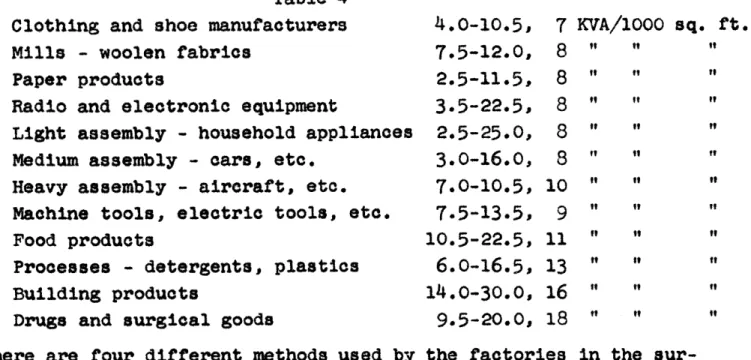
To show the power required by different industries and to give some idea of the machine density, the total plant demand may be expressed in terms of KVA/1000 sq. ft. which is roughly equivalent to watts/sq. ft. The amount of power used by the factories in the sample varies from 2 to 37 KVA/1000 sq. ft., depending of course on the manufacturing process, the degree of mechanization, and the machine density. The range and the normal figure for the different types of manufacturing represented is shown in Table 4.
Table 4 Clothing and shoe manufacturers Mills - woolen fabrics
Paper products
Radio and electronic equipment
Light assembly - household appliances
Medium assembly - cars, etc. Heavy assembly - aircraft, etc.
Machine tools, electric tools, etc. Food products
Processes - detergents, plastics Building products
Drugs and surgical goods
There are four different methods used vey for distributing the power to the
4.0-10.5, 7.5-12.0, 2.5-11.5, 3.5-22.5, 2*5-25*0, 3.0-16.0, 7.0-10.5, 7.5-13.5, 10.5-22.5, 6.0-16.5, 14.O-30.0, 9.5-20.0, by the factories in utilization points. 7 KVA/1000 sq. ft. 8 t t t 8 t f" t 8 It t 8 " " 8 "t 10 "i t 9 t t 11 " " 13 "t 16 " " 18 ft the sur-The
choice of method depends on the total plant demand and the incom-ing voltage. The methods are tabulated below.
Table 5
1. Incoming power to master substation to unit substation to machines.
2. Incoming power to unit substation to machines.
3. Incoming power to master substation to machines.
4. Incoming power to machines.
The first two methods are used when the total plant demand is rela-tively high, i.e. over 2000 KVA. The use of a master substation depends on whether the power supply is higher than voltage which codes and economics allow to be transmitted through the buildings. The master substation is usually located outside the plant either in the open or in a power house. In some cases it belongs to the utility company. From the master substation the primary cable is usually taken overhead to the unit substations which are located near areas of high power consumption. This system gives the maxi-mum flexibility with low cost because there are no long secondary runs from the main transformer to machines, the voltage drop is
feeders make machine relocation easier and if necessary for pro-duction line changes, the unit substations can be moved. The last two methods of power distribution are used when the total plant demand is less than 2000 KVA. Again the installation of a master substation depends on the voltage of the incoming power.
Where several utility voltages are available, the choice is based on the relative cost of power and the distribution system the voltage requires.
The type of circuit used is usually determined by the reliability required in the power distribution system; for instance, a higher reliability factor may be needed if the type of manufacturing in the plant involves continuous processes. The primary circuit runs from the master substation or main switchgear to the unit substa-tions, and the secondary distribution system feeds the machines from the unit substations or in the case of small plants, from the main substation. Either circuit may be of three types. In a simple radial circuit, which is by far the most popular and also the lowest in first cost, one feeder serves each substation or
uti-lization network. A selective radial system has an alternative feeder to each substation or busduct, and in a looped system all substations or distribution networks are connected together. The
looped circuit layout is not common in industrial buildings, and it is only used where the power load varies appreciably from place to place. In the sample there is no indication that the plants which have continuous processes favor any particular type of
cir-cuit, though they frequently locate the primary cable under the floor for increased reliability.
The means of secondary distribution is almost evenly divided be-tween busduct and cable in conduit, but the factories that use busduct are primarily the assembly and metal-working industries and those which make frequent layout changes. Busduct, especially the plug-in type, is extremely flexible. To relocate a machine, it is simply disconnected, moved, and reconnected without any changes in the machine power supply if the busduct is at the same height throughout the factory. The secondary distribution voltage
is usually 480 or 440, though in many cases lower voltages are used. The higher voltages are becoming more common, and two
respondents complained that their 208-volt system was inadequate. The distance between the utilization busduct in the industries where it is primarily used for secondary distribution varies from
20 to 100 feet with about 40 feet being the usual spacing. Artificial Lighting
As one would expect, fluorescent lighting is the normal means of lighting modern factories, but there are still plants, even re-cent ones, which have incandesre-cent or mercury vapor lighting. The factories that use mercury vapor are chiefly the assembly and
tool-making industries, and incandescent tends to be installed where the population density and the lighting levels required are
low. These forms of lighting are not limited to the factories
which have overhead natural light, which makes it surprising that mercury vapor is used in the industries which often have critical
visual tasks. The average level in the manufacturing areas of
the factories in the sample is 40 foot candles, but it varies ten foot candles each side of this for different processes. The aver-age figure for different types of manufacturing is given below.
Table 6
Processes - detergents, plastics Mills - woolen fabrics
Heavy assembly - aircraft, etc. Paper products
Building products
Machine tools, electric tools, etc.
Clothing and shoe manufacturers Light assembly
Medium assembly Food products
Radio and electronic equipment Drugs and surgical goods
35 35 35 35 35 40 40 40 40 45 50 50 foot candles ti " "
Heating and Ventilating
The heating and ventilating of American factories is almost al-ways by the same air circulating system. In the sample there were only three exceptions to this norm, and they were all rela-tively early plants which used a low temperature radiant heating system, and two were multi-story. There are rather more examples which used a mixed heating system, but this too is far from com-mon, and in many cases the respondents may have included the
heat-ing system of the office space. The normal system of heatheat-ing, where there are no other climatic control complications, is by unit heater, drawing fresh air in through the roof and frequently
blowing directly into the manufacturing space but sometimes
dis-tributing the air through a duct system. Ducts tend to be used when the ceiling height is low and the population density high to achieve proper distribution. The use of more complete climatic control--filtered air, humidity control, and cooling--depends pri-marily on the process. For instance, the plants which manufacture precision instruments and those that require extreme cleanliness have most of the manufacturing area supplied with filtered air. The processes which use material on which moisture has an adverse effect--for example, the cardboard container manufacturers--have humidity control, and so on. In addition there are other factories of course where all or part of the area is air conditioned for the employees' benefit. These examples tend to be concentrated in the types of manufacturing which demand a high population density. Of the hundred factories in the sample, 28 had more than a quarter of the area filtered, 15 a quarter under humidity control, and 18 a quarter of the area cooled.
The exhaust side of the ventilation system is usually by roof ex-haust fans when a simple unit-heater system is used. There are however a considerable number of factories which have part natural ventilation and a few which rely completely on this means. Most of the recent examples which rely on natural ventilation are under
50,000 square feet in area, though some of the earlier ones are much bigger. A ducted air exhaust system with provision for
re-circulation is necessary of course when the factory is air condi-tioned. Very little information on the rate of air change and the amount of reclrculation was given in the completed questionnaires. The air change rate appears to vary from 1/2 to 20 air changes per hour with 5 to 10 being the average. The highest rates of air
change occur in the factories which do not have air conditioning, of course. The maximum recirculation of air varies from 10 per cent to 100 per cent, but about 75 per cent is the normal figure.
Materials Handling Equipment
The type of materials handling equipment used in a factory has an important influence on the structure. For instance, if fork lift trucks are necessary to the process, the clear internal height
must be adequate to allow them to stack to the limit of their capa-city and the floor strong enough to carry the load. Again, if
overhead conveyors are used, the structure must be strong enough to support the weight of the conveying system and its load in ad-dition to the roof.
From the answers given to this section of the questionnaire, the most striking thing from the building design aspect is the almost universal use of fork lift trucks. These appear to be used as
much as the rest of materials handling equipment put together.
Beyond this it is difficult to generalize, and the appendix giving the detailed answers to the question should be studied. It seems that the industries which primarily use fork lift trucks are
paper product manufacturers, building products, processes such as detergents, and woolen mills. There are of course other plants which use fork lift trucks a great deal, but they do not seem to
be used by the particular industry as a whole.
Overhead conveyors are used in 37 of the 100 plants, but only
five manufacturers use this means of handling more than any other.
The industries which use overhead conveyors appreciably are radio and electronic equipment manufacturers, light assembly such as household appliances, and medium assembly--cars, etc. Overhead handling is also used to some extent by the manufacturers of tools. The heavy assembly industry is the only one which uses cranes for most of its materials handling, but 43 plants have a
limited amount of overhead handling by this method. In fact
there are only 20 factories in the survey which do not have some form of overhead-moving equipment. Floor oonveyors--roller, wheel,
or belt--are not often actually fixed to the structure, but in some factories this is the case, Only six plants do more than 50 per cent of their handling by this method. Elevators of course are mainly used in multi-story factories, and since they are
nor-mally installed at the time the structure is built, they need not
be considered here. The only other type of materials handling
equipment which is used a great deal by the factories in the sample is hand trucks, and these and power trucks do not affect the structure as much as the fork lift type.
Speed of Construction
The speed with which a factory building can be constructed is one
of the most important factors in the design, since once the deci-sion to build is made, the manufacturer's capital is unproductive
until the plant is in operation. The need for fast erection may
lead to compromises in the design of the structure, and it is un-doubtedly the prime reason why a steel frame is the most popular construction.
The duration of construction of the factories in the sample varies
considerably, partly as one would suppose with the sise of the
building, but this does not account for every case. Multi-story buildings generally take longer to build than single-story examples because the construction is normally reinforced concrete or fire-proofed steel frame. The multi-story factories for which this in-formation is given vary from 15,000 to 600,000 square feet and the
normal construction time for a multi-story building of 200,000 square feet is 15 months. Single-story factories of course are frequently built much more quickly. The shortest time reported in the survey in 3 months for a 50,000 square foot factory, and the longest 35 months for a 600,000 square foot factory. On the average a 200,000 square foot factory can be built in 10 months, though if required, this can be reduced to 8 months. Bigger fac-tories do not take much longer to build; there are examples in the survey where 500,000 square feet have been built in 11 months
and 780,000 square feet in 12 months, but 16 months would be a
more reasonable time.
CHAPTER 2 - THE FACTORS INFLUENCING THE DESIGN REQUIREMENTS
A survey of existing buildings is one way of arriving at the de-sign requirements of multi-purpose factory buildings, but for some of the most important criteria it is possible to check the
conclusions against the equipment which determines them. In this
chapter the factors which influence the major decisions are tabu-lated and discussed, and where standardized equipment determines the criteria, the critical dimensions or weights are given.
Bay Size
The bay size is determined by: 1. The adaptability required; 2. The size of product;
3. The type of assembly;
4. Amount of load-hanging capacity required;
5. Bridge crane sizes.
In most factories the bay size is not the most important design factor, as many people believe. Where the size of the product controls the column spacing, as for instance in a factory making heavy road machinery or aircraft, the dimensions must obviously be big enough for the product to pass through. In addition, there must be enough space between the lines of columns for easy access by machines, materials, and men. But there are very few products which are large enough to influence the bay size, and then the most important factor is the desire for clear floor space for a good production layout, and subsequent changes. The ideal is a factory with no internal columns at all, but this is seldom if ever possible and the cost prohibitive. Thus the bay size is a balance between the adaptability required and the cost
of framing the span, for beyond a certain limit the weight of steel required increases out of all proportion to the usefulness
of the bigger bay size. In this respect it should be remembered that the capital costs of the factory building are only 5 to 7 per
cent of the total production costs, and if an increased bay size results in higher productivity, it may well pay for itself. It has been said that every column wastes 10 square feet of floor space, and this should be taken into account when calculating the relative costs of different bay sizes.
From the survey there appears to be a preference for square bays, and although these are normally more expensive than rectangular ones, they do have the advantage of permitting the maximum flexi-bility for production line layouts in both directions.
If the amount of load-hanging capacity required is substantial, it will reduce the economical bay size in proportion to the extra load to be carried.
Where overhead bridge cranes are used, the column spacing in one direction is usually considerably less than the maximum span, to reduce the weight and size of the crane rails which span between the columns along the short dimension. The maximum span may also
be influenced by the size and cost of the bridge cranes that are
available. The large capacity models come in spans up to 100 feet, but the small load type, which use an I-beam girder, are
limited to 50 feet. Clear Internal Height
The clear internal height is determined by:
1. Working height of stacking equipment and load;
2. Height of machine tools;
3. Clearance required for overhead handling equipment;
4. Use of mezzanines and overhead walkways;
5. Size of product.
The clear height to the bottom of the roof structure is the most important dimension to be decided in designing a factory, since
it is the main factor in determining the adaptability of the build-ing. The average height of present factories is about 18 feet, and this is four feet higher than the average of a few years ago.
The standard stacking height of the smaller fork lift trucks is
10 feet, but most of them can also be obtained with a 12-foot
stacking mechanism. If to this is added a load height of 8 feet, which is not unreasonable, the top of the stack of material is 20
feet high. In addition, some clearance is essential, and this es-tablishes the clear height of the factory at 21-22 feet. The
larger high-lift fork trucks stack to a height of 18 or even 24 feet. These are not often used inside the normal factory, but nevertheless the possibility remains, Of course, it is probable that vertical stacking space will only be required in the warehouse areas of the factory, but if the space is to be adaptable to
changing requirements, adequate height for stacking is important everywhere.
The following table gives the recommended heights required in
manufacturing areas. 1
Table
Without Overhead With Overhead
Type of Production Equipment Equipment
Small-product assembly 9-14 feet 10-18 feet
on benches
Large-product assembly Max. height of Max. height of
on floor product + 75% product + 125%
Small-product forming Height of ma- Height of
ma-chinery + 10% chinery + 150%
Large-product forming Height of ma- Height of ma-chinery + 125% chinery + 125% The height of machine tools may be anything up to 18 feet for heavy, large capacity units, but 12 to 14 feet is a more reason-able figure for the higher machine tools which are likely to be used in general manufacturing areas. Many tools of course are less
than the height of the operator.
The clearance required for normal bridge cranes is 7 feet for up to 15 tons capacity, but for heavier cranes this will be increased to 10 feet. If to this is added the height of the load and that of machine tools, it gives a minimum clear internal height of about 30 feet.
Overhead monorail hoists require at least 4 feet clearance, and with a load the minimum height to clear machine tools must be about 22 to 24 feet. Neither overhead cranes nor hoists are com-mon throughout most of the manufacturing areas covered by the sur-vey, but provision must be made in an adaptable factory for over-head monorail conveyors. The clearance required for these is
difficult to establish. The depth of the track and trolley is seldom more than 18 inches, but the track cannot normally be placed hard against the underside of the structure, and the load may vary considerably. For normal loads the clearance required will be 6 to 8 feet, but for bulky objects or small loads in tiered baskets the clearance may well be 10 feet. This gives a clear internal height of about 20 feet.
If mezzanine toilets or overhead walkways are suspended below the
bottom of the trusses, they will "equire about 9 feet, including the depth of the floor structure. Another 9 feet must be considered the absolute minimum headroom under the mezzanine, and this should be much more if it is not to hamper layout changes. This gives a minimum height of 18 feet, but 22 would be considerably better.
It is of course probable that more than two of the factors described above will occur at the same place. This is especially true if overhead walkways and overhead monorail conveyors are used. In this case a minimum height of 26 feet will be required unless the production floor is interrupted by the conveyor dipping down.
Provision for Hanging Loads
The load capacity of the structure depends on:
1. Weight of overhead conveyors and load;
2. Weight of monorail hoists and load;
3. Weight of parts of machines to be lifted out for repair; 4. Whether mezzanines or overhead walkways are required;
5. Weight of unit substation and busduct; 6. Weight of ventilation equipment.
The factories in the sample had a hanging load capacity varying from 100 to 10,000 pounds at panel points and 100 to 2,000 pounds anywhere. The average, however, is 2,000 pounds at panel points and 500 to 1,000 pounds anywhere, and this appears to be the ab-solute minimum that is acceptable. The load centers are nor-mally from 8 to 12 feet apart, but they are sometimes much more. The load carrying capacity and the weight of overhead monorail conveyors is normally up to 200 pounds per linear foot, but there are conveyor trollies made which will support much more. Since the normal support centers are 10 feet apart, this gives a point load of 2,000 pounds.
Monorail hoists, which are suspended from the roof, handle con-siderably heavier loads, in fact up to 30,000 pounds, although
10,000 pounds is probably an average figure. The weight of the
hoist unit itself is also heavy, varying from 750 to 4,500 pounds with the 10,000 pound capacity units weighing' about 2,000 pounds. This gives panel point loadings of 6,000 pounds for the average hoist and up to 13,000 pounds for the heavy capacity ones. Whether full provision for the largest hoists is required will depend on the weight of component parts of machine tools that have to be
lifted out for repair or on the weight of the product. Monorail
hoists are usually the only type of lifting equipment which is
suspended from the roof. For heavier loads bridge cranes are used, and these rest on tracks supported by the columns.
The weight of the heaviest component parts of machine tools is
one of the most important factors determining the load-hanging capacity. To be able to lift out the part of a machine needing
repair overhead is frequently the only way of removing it without disturbing the production on adjacent machines. As factories be-come more mechanized and the machine density gets higher, this will become of' increasing importance, especially where there are
long continuous transfer machines alongside. Unfortunately, the manufacturers of machine tools do not have this Information
read-ily available. One of them, however, stated that the bare cast-'Ow "