algorithm for robotic image-guided micromanipulation
The MIT Faculty has made this article openly available.
Please share
how this access benefits you. Your story matters.
Citation
Yang, Liangjing, Kamal Youcef-Toumi, and U-Xuan Tan.
“Detect-Focus-Track-Servo (DFTS): A Vision-Based Workflow Algorithm for
Robotic Image-Guided Micromanipulation.” 2017 IEEE International
Conference on Robotics and Automation (ICRA) (May 2017).
As Published
http://dx.doi.org/10.1109/ICRA.2017.7989636
Publisher
Institute of Electrical and Electronics Engineers (IEEE)
Version
Author's final manuscript
Citable link
http://hdl.handle.net/1721.1/120058
Terms of Use
Creative Commons Attribution-Noncommercial-Share Alike
Abstract— Robotic image-guided micromanipulation
contributes towards the ease of operation, speed, accuracy, and repeatability in cell manipulation. However, such technology is not fully exploited because of the challenges in the integration of robotic modules with existing microscope systems, and the difficulty in incorporating robot assistance seamlessly into the workflow. In this paper, we propose a vision-based workflow algorithm termed Detect-Focus-Track-Servo (DFTS). It facilitates easy integration of robotic modules. It also supports user interactions while minimizing the need for manual intervention and disruption to workflow through automatic detection, focusing, tracking and servoing. Experimental results suggest satisfactory detection accuracy of 99.0 % at 70 µm tolerance. The robustness test suggests no difference in the accuracy under blurred and cluttered images. The self-focus algorithm is also demonstrated to bring the tip into focus consistently. The track-servo algorithm achieves low sub-pixel uncertainty. By proposing the DFTS workflow algorithm, we hope that the level of autonomy and ease of deployment in robot and vision modules for micromanipulation can be improved so as to open up new possibilities in the development of robotic image-guided cell manipulation.
I. INTRODUCTION
Robotic image-guided micromanipulation has great potential in the advancement of cell manipulation technology. It incorporates motion control and vision in micromanipulation under a microscope. This can provide dexterous and visual support during cell manipulation the way it has contributed in the field of microassembly and fabrication [1, 2]. In the field of cell manipulation, a user-operated robot micromanipulator, coupled with microscopic vision, means that operators can move and see at microscale in an easier and more effective manner. Such technology, hence, promises better ease of operation, speed, accuracy, and repeatability. These are crucial in both the development and execution of experimental protocols in the study of cell biology [3].
However, there remain challenges in translating the existing state-of-the-art technology in robotics and machine vision directly for cell manipulation. There are two reasons for the relatively lack of readiness in robotic image-guided micromanipulator for cell manipulation. Firstly, there is a gap in unifying the research and development efforts in vision and
*Research supported by SUTD-MIT International Design Centre(IDC). Liangjing Yang is with the Pillar of Engineering Product Development, Singapore University of Technology and Design, Singapore (phone: +65-6303-6600; fax: +65 6779 5161; e-mail: [email protected]).
Kamal Youcef-Toumi is with the Mechanical Engineering Department, Massachusetts Institute of Technology, Cambridge, Massachusetts 02139, USA (e-mail: [email protected]).
U-Xuan Tan is with the Pillar of Engineering Product Development, Singapore University of Technology and Design, Singapore (e-mail: [email protected]).
motion control for cell manipulation. While both fields have advanced remarkably, the bottleneck for robotizing micromanipulator systems under microscope lies in the integration of its vision and motion control module. Without effective techniques in the calibration or registration of microscope vision and the micromanipulator motion control, isolated research and development efforts from individual fields could not translate to meaningful advancement in cell manipulation. To bridge this gap, an operation framework that combines intelligent recognition of tracking targets and closed-loop motion execution of user-specified path is needed. Secondly, the need for robotic assistance remains an unobvious latent need to users because of the nature of cell manipulation, which relies heavily on complex manual operations. This calls for elegant operation framework that integrates seamlessly to the user’s workflow and provides timely assistance to tedious tasks without having to burden users with additional procedures or setup excessively.
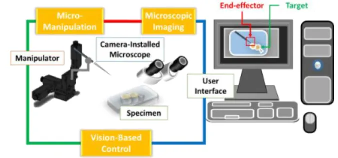
Based on the identified needs and specifications, we proposed a vision-based workflow algorithm termed DFTS for robotic image-guided micromanipulation. The contribution is two-fold. Firstly, the integrated framework addresses the need for a flexible solution in integrating microscope vision and micromanipulator motion. Figure 1 illustrates the framework overview of a robot image-guided manipulation system integrated with microscope vision and robotic manipulator. Secondly, the DFTS algorithm reduces the need for operator interventions, hence, minimizing disruptions to the workflow. These two aspects cover the identified needs mentioned.
Figure 1. Overview of DFTS in robotic image-guided micromanipulation
The scope of this paper is organized in sections starting from a discussion of existing related work and some of the issues that have yet to be addressed. After reviewing on what have and have not been done, we present our proposed method with in-depth explanation of the concept and implementation. Experimental setup, procedures, and conditions will be documented in Section IV. Finally, the results will be discussed in Section V before concluding the paper by summarizing the contributions and the significance of this study including the prospective future work in Section VI.
Detect-Focus-Track-Servo (DFTS): A Vision-Based Workflow
Algorithm for Robotic Image-Guided Micromanipulation
Liangjing Yang, Kamal Youcef-Toumi, Member, IEEE, U-Xuan Tan, Member, IEEE
II. RELATED WORK
Vision-based control is an important field for the development of the robotic micromanipulator system, as micromanipulation of cell are mostly, if not always, guided by microscopic imaging. There are many works that develop intelligent visual guidance for cell manipulation [4-6]. However, the state-of-the-art technology has not been fully leveraged upon for effective robotizing of image-guided micromanipulation. The challenge lies in the integration of the developed techniques to micromanipulator seamlessly for image-guided manipulation. This is challenging in both setup and operation because of the unique requirements for robot-camera registration.
Existing techniques for registering the microscope image coordinate system to the micromanipulator joint coordinate system are mostly based on calibration prior to the operation. For microscope systems with fixed camera position, the mapping between the image and manipulator coordinates can be solved using 3D patterns [5-8] or manipulator kinematics [9, 10]. The pattern-based methods used in micromanipulator systems are usually modifications of established approaches in photogrammetry and robot vision. Examples are the modification of Tsai’s [11] and Zhang’s [12] method by Zhou and Nelson [7], and Ammi et al. [5, 6]. However, these techniques, in microscale level, poses challenges like calibration structure fabrication, thermal influence, and intermediate transformation uncertainty. Although the calibration method, using manipulator kinematics proposed by Zhang et al. [10], may overcome some of these issues, it is based on parameterization of output data, which ignores the intrinsic-extrinsic structure of the camera matrix. Recalibration is required whenever optical properties change.
There are also techniques that use direct visual servo to avoid the issues of calibration [13-15]. A direct visual servo method which expresses an error signal in terms of the image feature parameters was proposed by Sun and Nelson [10, 11]. A template similarity-score based approach for autofocusing was also proposed to position a preselected template patch in focus. This is an important contribution that addresses the need for image focus during microscopy apart from the traditional passive histogram-based methods [16]. In our previous work [15], we proposed an uncalibrated approach for easy integration of a 3D micromanipulator to a microscope. It also uses a similarity score-based approach to maintain the tool tip in focal plane while manipulated by the user. Although it allows users to intuitively control micro-needles or holders via an interactive display, it requires users to bring the tool in focus followed by manually selecting a region of interest (ROI) as a template prior to automatic tracking. These template-based approaches disrupt the workflow in robotic manipulation. Ideally, the developed robotic assistance should minimize the need for additional setup or manual intervention through automatic ROI specifying for self-focusing.
The proposed DFTS workflow algorithm aims to address two main issues identified from existing works. Firstly, the integrated framework aims to provide a flexible solution for integrating and deploying robotic vision-based module to microscopy system. Secondly, the algorithm aims to reduce the need for operator interventions hence minimizing disruptions to the workflow.
III. DETECT-FOCUS-TRACK-SERVO
A. Conceptual Overview
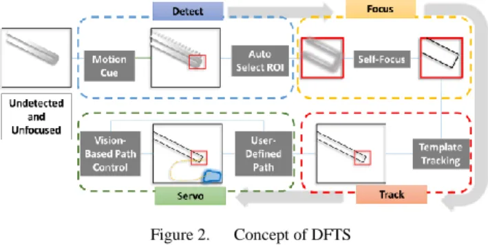
The DFTS workflow algorithm consists of four components, namely Motion-Cue Automatic Detection, ROI-Specific Self-Focusing, Template Tracking, and Visual Servoing. The design concept of the workflow algorithm is illustrated in Figure 2.
Figure 2. Concept of DFTS
For an unfocused tool tip, a motion-cue is given to enable its detection and localization. The coordinates of the localized tool tip can be used to select an appropriate ROI. Based on this automatically defined ROI, self-focusing is performed to bring the tool tip in focus. This ROI is further used as a template for template-based tracking. Finally, visual servo to execute the user-specified path is performed.
B. Detect: Motion-Cue Detection
The motion-cue detection uses image difference between temporally adjacent frames to detect active movement input of the tool tip in the scene. The strongest corner feature is subsequently extracted from the difference image to further localize the tip. In this work, Harris corner detector [17] is used. The strength of the feature can mathematically be represented using a feature response,
21 2 1 2
C k (1)
where k is a tunable value while λ1 and λ2 are the eigenvalues
for the covariance of the sum-of-square-difference (SSD)
2 , ( , ) ( , ) Q P SSD p q w x y
I p q I p x q y (2)of the patch I centered on (p,q) and itself when shifted (x,y). To avoid tedious computation of the eigenvalues, Harris and Stephens[17] used the structure tensor S of the SSD to define an inspired feature response function. In our work, the location of the tip in the difference image is determined by the strongest corner response of this inspired expression written as
2
max det( ) trace
tip
C S k S , (3)
Note that the corner detection is done in the domain of the difference image. The location of detection is subsequently represented in the actual microscopic image.
The proposed approach differs from the other common motion detection method which is usually only capable of detecting the presence of motion. Here, coordinates of the final position are required as well. The aim is to localize the tip where an ROI can be defined automatically as a template, which can then be focused and tracked specifically in the later
stage of DFTS. Conventional feature-based detection algorithms rely solely on visible features and assume that the images are in focus. This may not perform satisfactorily in blurred and unfocused images. Performing corner detection on difference images solves this problem because the moving tool is enhanced while the static background is suppressed. As a result, the moving tip can be easily detected and localized.
C. Focus: ROI-Specific Focusing
Upon detection of the tool tip using motion-cue detection, an ROI is specified for regional histogram-based self-focusing to be performed. The term self-focusing is used to differentiate this step from the conventional autofocus problem. The latter involves moving the lens of the camera to bring the object in focus. In our case, we are interested to move the tool tip (the object) to the focal plane. Background scene remains unchanged while the localized tool tip is brought to focus. Usually, in the case of manual operation, the specimen is fixed in focus while the user moves the tip to the focal plane. Our developed method brings the tip to focus for the user automatically.
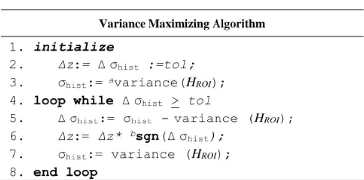
To realize the self-focusing mechanism using an online passive approach, a histogram-based variance maximizing method is implemented for the DFTS algorithm. Other common histogram-based passive methods for microscopy [18] can also be used because the gradient ascending update rule used in this work can be readily generalized for other focus functions [16]. This self-focusing algorithm uses statistical variance σhist of the histogram HROI associated with
the ROI to infer if it is in focus. The objective is to maximize σhist by adjusting the depth in a gradient ascending manner
until within a tolerance tol as pseudo-coded in Table I.
TABLE I. PSEUDO-CODE FOR ROI-SPECIFIC SELF-FOCUSING
Variance Maximizing Algorithm
1. initialize
2. Δz:= Δσhist :=tol;
3. σhist:= avariance(HROI);
4. loop while Δσhist > tol
5. Δσhist:= σhist -variance (HROI);
6. Δz:= Δz* bsgn(Δσhist);
7. σhist:= variance (HROI);
8. end loop
a. variance() is a function that returns the statistical variance; b. sgn() extracts the sign
Note that this updating mechanism is similar to a similarity score-based depth compensation approach proposed previously for 3D motion control [15]. However, unlike the previous application, a focused template of the tip is not initially available. Therefore, instead of using the template-related similarity score, the statistical variance σhist of
HROI is used.
Although this method appears to be a convenient passive approach for self-focus, it fares badly for moving scene. This is true for most other histogram-based methods. Therefore, this approach is only used for the initial self-focusing step to enhance the automatically selected template. To maintain focus for the tip while in motion (i.e., during the track-servo step), the similarity score-based approach [15] is implemented and will be discussed in the next section.
D. Track-Servo: Template Tracking & Path Execution
Once the tool tip in the ROI is brought to focus, the next step is to use it as a template for tracking in subsequent frames. This template-based tracking, coupled with visual servo, in turn allows the user to intuitively manipulate the tool tip on the microscope image display. This component of the workflow algorithm is referred to as track-servo.
The track-servo component is essentially an adaptation of the algorithm proposed in our previous uncalibrated approach for vision-guided micromanipulator [15]. It takes in an ROI as the tracking template and performs 3D manipulation using a similarity score-based compensation method to constrain the motion within the focal plane. When incorporated to the DFTS workflow algorithm, users no longer need to manually focus the tool tip and define the ROI. These are actually tedious operations to do manually without clear vision of the tool tip. The motion-cue detection not only helps to automatically detect tool tip even in blurred condition, it further selects the appropriate window for ROI-specific self-focusing. User intervention is, therefore, minimized to facilitate a seamless integration of robot-assistance in micromanipulation.
Once the tracking template is obtained, the algorithm searches for matches in the subsequent frames of the microscope video stream on-the-fly based on a score wncc determined by the normalized cross-correlation of a template g with a particular patch f. For a U x V image and P x Q patch, the normalized cross-correlation wncc(u,v) at coordinates (u, v) of a template g(p,q) and the image patch f(p,q) is expressed as
0.5 2 2 0 0 0 0 0 0 , Q Q Q P P P ncc p q p q p q w u v G F G F
where G
g p q
, g
and F f p u q v
,
f u v, . Notationg and f represent the mean intensity value in thetemplate and the region overlapping the patch, respectively. Visual servoing in 3D is realized by decoupling the planar and depth motion as described in our previous work [15]. As the track-servo method is regulated by similarity score, it recognizes occlusion and stop safely. The motion of the tip is maintained in the focal plane using a depth compensation mechanism. The algorithm is similar to that described in Table 1 except that the objective is to maximize similarity score wncc instead of the σhist. Also, in contrast to self-focusing, the
score-based depth compensation is done concurrently while the tip is being manipulated. This is possible because the similarity score-based approach, unlike the histogram-based approach, is less prone to the influence of motion in the scene.
IV. EXPERIMENTAL SETUP
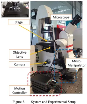
Experiments were conducted to quantitatively evaluate the individual modules of the DFTS workflow algorithm. The microscope system for the experiment is shown in Figure 3. Microscope imaging is done by an inverted microscope (Leica DMi8; Leica Microsystems GmbH, Germany). This is installed with five different objective lens (5x, 10x, 20x, 40x, and 50x). For the evaluation test, the 5x magnification (Numerical Aperture; 0.12) is used. A C-Mount USB digital camera (AM7023CT Dino-Eye, AnMo Corp., Taiwan) is used to acquire the microscope vision at 30 frame-per-second (fps).
The micromanipulator is a 3-axis actuated microstage (8MT173; Standa Ltd., Lithuania) with a workspace of 20 x 20 x 20 mm3. The resolution of a complete step is 1.25 µm. A
multi-axis controller (8SMC4; Standa Ltd., Lithuania) is used. The application and user interface are developed in LabVIEW Development Suite (National Instruments Inc., USA) with its image acquisition, image processing, and control modules executed with different resources of the multi-core processor (Intel® Xeon® CPU E5-1620 v2 @ 2.5GHz). These are implemented in a 64-bit Windows 8 platform terminal.
Figure 3. System and Experimental Setup
V. RESULTS AND DISCUSSION
A. Demonstration: DFTS for Image-Guided Manipulation
The DFTS workflow algorithm is demonstrated in the attached Media. In the video, an originally blurred tip is brought to focus by the motion-cue detection and ROI-specific self-focusing. Subsequently, the manipulator executes user cursor-specified path on the interactive display using the track-servo algorithm of the DFTS workflow.
B. Detection: Uncertainty and Accuracy
In designing the test for motion-cue detection component, it is important to recognize that the requirement is not simply to detect the presence of any movement. The more critical role of this detection stage in the DFTS scheme is to localize the tip. This means that the localization precision and accuracy has to be quantitatively evaluated to ensure appropriate selection of ROI. An accurate selection of ROI in this context means correct localization of the tool tip. This is referred to as a successful detection while an inaccurate localization, on the other hand, is referred to as a failed detection.
In this test, a continuous linear path is executed to generate a series of detected locations along the path. As the manipulator-executed path is known, it can be used as a datum line for error measurement. The detection of tool tips along the paths are shown in Figure 4. Based on the trajectory, we can infer the localization uncertainty and the detection accuracy.
The mean distance from the known trajectory indicates the uncertainty of the localization. The mean error (i.e. the orthogonal distance of a point to the datum line) is 1.78 pixels. Figure 5 shows the error distribution over the 492 frames.
Figure 4. Detection of tip along datum line (known input motion)
Figure 5. Error Distribution over the 492 frames
It can be observed that the errors are generally below 5 pixels except for a few obvious outliers which can easily be eliminated using the known motion of the manipulator. In practice, only the finalized location is used to specify the ROI during the operation. The high standard deviation associated with the points exceeding a given tolerance can easily be identified and not used to specify the ROI. However, it is not the intention of this test to quantify the accuracy based on localization magnitude. Neither is motion tracking the objective of the motion-cue detection. There is no issue in identifying a fail detection as the outliers are obvious given the known motion path.
Nevertheless, the magnitudes of the error enable us to further quantify the rate of accurate localization i.e., success rate. This demonstrates the chances of success or failure in the motion-cue detection. Since the ROI is set to be 90 x 90 pixels, a conservative tolerance will be 20 pixels (=70 µm; approximately half the size of human embryo). At this tolerance, 99.0 % of the detections are successful.
To further quantify the detection accuracy over a range of tolerance, the success rate is plotted against the respective tolerance bin. In other words, the detection is accurate if and only if the error associated is within the defined tolerance. Figure 6. shows the percentage of correctly detected coordinates at different tolerance.
Figure 6. Rate of correct detetcion at different tolerance; (Top) For 60 bins of tolerance value (Bottom) Zoom-in to range 1-20
For example, setting the tolerance at 5 pixels (=17.5 µm; approximately half the dimension of human skin cell) means that 98.2 % of the detection are considered correct detections as shown in the bottom graph of Figure 6 which is a zoom-in of the top graph from 1- to 20-pixel tolerance. Similarly, 100% of the detections are successful if detections with error less than 52 pixels are considered accurate detections.
C. Detection: Robustness to Imaging Condition
It is important for the detection to be robust against adverse imaging conditions. This is because the tool tip is not yet in focus and background cluttering may adversely influence the detection process before an ROI is even defined. To demonstrate the robustness, a continuous path over the blurred and cluttered vision as shown in Figure 7 is performed. In total 1410 frames of detection were recorded.
Figure 7. Adverse image condition with a blurred and cluttered scene; dotted lines with shadow are overlays for illustration
The tool tip moved from the bottom-right of the FOV to its top-left as shown in Figure 8. Based on the trajectory, we can infer the localization uncertainty and repeatability, as well as the detection accuracy. The mean error represented by the orthogonal distance from the actual motion is 3.21 pixels. It can be observed that general detection remains accurate despite some clear outliers. The motion-cue detection method turns out to be robust against blurred and cluttered vision. Tolerance at 20 pixels (=70 µm) obtained a success rate of 99.2 % which is comparable to the results without cluttering.
Figure 8. Detection of tip along datum line under adverse conditions
While it is true that adverse imaging condition may increase the uncertainty of detection as suggested by the difference in the mean error, it has insignificant effect on the accuracy as suggested by the success rate. As mentioned, the motion-cue detection is concerned only with the final localized position. This non time-critical operation can be executed repeatedly until the estimated position is in consensus with the motion.
D. In-plane Focusing
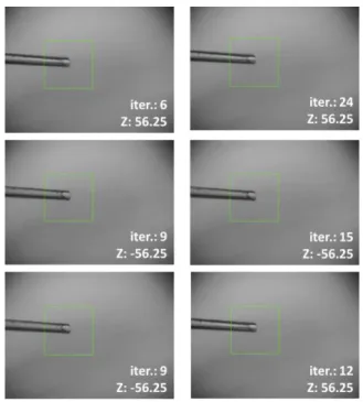
To evaluate the self-focusing mechanism the tool tip is intentionally blurred. Figure 9 shows the intentional blurring of the tool tip by displacing it -375 µm away from the focal plane (further away from the imaging plane). The results of self-focus at 6 different trials are shown in Figure 10.
Figure 9. Intentional blurring by bring tip 375 µm away from focal plane
Figure 10. Six cases of self-focusing outcome; Z is the distance from focal plane (µm); iter. refers to the number of iterations
On average, 12.5 iterations are required before a satisfactory focus is reached. This takes about 18.8 s at an actuation speed of 125 µm/s. The self-focusing mechanism brings the tip 75% closer to the focal plane. There is also no significant visual difference between the results and the manually selected “ideal focus”. This can be verified based on visual inspection of Figure 10. In fact, the mean difference between σhist and that of the “ideal focus” is only 1.31%.
E. Accuracy in Track-Servo
The tracking accuracy in the track-servo component of DFTS can be evaluated by analyzing the tracking error along input trajectories. A square pattern consisting of 4 linear paths is executed using the track-servo algorithm. The tracked points in each frame are plotted in Figure 11. The paths are labelled as Path A (377 frames), B (318 frames) , C (337 frames), and D (365 frames) with a total of 1397 tracked frames. Based on the trajectory, we can infer the localization uncertainty and repeatability. The mean errors represented by the orthogonal distance from the actual linear motion are 0.31 pixels, 0.41 pixels, 0.23 pixels and 0.26 pixels for path A, B, C, and D, respectively. The subpixel precision of the visual tracking is satisfactory as it matches the innate uncertainty of the micromanipulator. In our experimental setup, the precision of the micromanipulator is 0.36 pixels (=1.25µm). Given an upgrade in the hardware, the precision is likely to improve.
Figure 11. Tracking profile of track-servo
VI. CONCLUSION AND FUTURE WORK
A workflow algorithm termed DFTS is proposed in this study to integrate microscope vision and manipulator motion for image-guided micromanipulation. The concept is to combine automatic detection and self-focusing of ROI, template tracking, and visual servo to execute user-specified path. The feasibility of the algorithm is demonstrated through experiments and quantitative evaluation.
The contribution of the proposed algorithm DFTS is two-fold. Firstly, the integrated framework addresses the need for a flexible solution in integrating and deploying robotic vision-based module for cell manipulation. Secondly, the algorithm reduces the need for operator interventions minimizing disruptions to user’s workflow. These two aspects cover the identified needs.
By proposing this DFTS workflow algorithm, we hope to facilitate intuitive user-robot interaction, advance the level of autonomy, and improve ease of deployment in robotic image-guided micromanipulation.
Future work will include integration of a motorized microscope stage and multiple robotic micromanipulators. The long-term goal is to create new possibilities in the development of robotic microscopy image-guided micromanipulation.
REFERENCES
[1] A. Sulzmann and J. Jacot, "3D computer vision for microassembly stations and microfabrication," in Intelligent
Systems & Advanced Manufacturing, 1998, pp. 42-51.
[2] M. Wang, X. Lv, and X. Huang, "Self-optimizing Visual Servoing Control for Microassembly Robotic Depth Motion," in
2007 International Conference on Information Acquisition, 2007,
pp. 482-486.
[3] J. P. Desai, A. Pillarisetti, and A. D. Brooks, "Engineering approaches to biomanipulation," Annu Rev Biomed Eng, vol. 9, pp. 35-53, 2007.
[4] M. Azizian, R. Patel, C. Gavrilovici, and M. Poulter, "Image-guided robot-assisted microscope objective lens positioning: Application in patch clamping," in Intelligent Robots
and Systems (IROS), 2010 IEEE/RSJ International Conference on, 2010, pp. 6149-6154.
[5] M. Ammi, V. Fremont, and A. Ferreira, "Flexible microscope calibration using virtual pattern for 3-d telemicromanipulation," in Robotics and Automation, 2005. ICRA 2005. Proceedings of
the 2005 IEEE International Conference on, 2005, pp.
3888-3893.
[6] M. Ammi, V. Frémont, and A. Ferreira, "Automatic camera-based microscope calibration for a telemicromanipulation system using a virtual pattern," Robotics, IEEE Transactions on, vol. 25, pp. 184-191, 2009.
[7] Y. Zhou and B. J. Nelson, "Calibration of a parametric model of an optical microscope," Optical Engineering, vol. 38, pp. 1989-1995, 1999.
[8] J. Bert, S. Dembélé, and N. Lefort-Piat, "Performing weak calibration at the microscale. Application to micromanipulation," in IEEE International Conference on Robotics and Automation,
ICRA'2007., 2007, pp. 4937-4992.
[9] G. Li and N. Xi, "Calibration of a micromanipulation system," in
Intelligent Robots and Systems, 2002. IEEE/RSJ International Conference on, 2002, pp. 1742-1747.
[10] Y. Zhang, M. Han, C. Shee, T. Chia, and W. Ang, "Self ‐ calibration method for vision‐guided cell micromanipulation systems," Journal of microscopy, vol. 233, pp. 340-345, 2009. [11] R. Y. Tsai, "A versatile camera calibration technique for
high-accuracy 3D machine vision metrology using off-the-shelf TV cameras and lenses," Robotics and Automation, IEEE Journal
of, vol. 3, pp. 323-344, 1987.
[12] Z. Zhang, "Flexible camera calibration by viewing a plane from unknown orientations," in Computer Vision, 1999. The
Proceedings of the Seventh IEEE International Conference on,
1999, pp. 666-673.
[13] Y. Sun and B. J. Nelson, "Microrobotic cell injection," in
Robotics and Automation, 2001. Proceedings 2001 ICRA. IEEE International Conference on, 2001, pp. 620-625.
[14] Y. Sun and B. J. Nelson, "Biological cell injection using an autonomous microrobotic system," The International Journal of
Robotics Research, vol. 21, pp. 861-868, 2002.
[15] L. Yang, K. Youcef-Toumi, and U.-X. Tan, "Towards Automatic Robot-Assisted Microscopy: An Uncalibrated Approach for Robotic Vision-Guided Micromanipulation," presented at the Intelligent Robots and Systems (IROS), 2016 IEEE/RSJ International Conference on, Daejeon, Korea, (accepted). [16] F. C. Groen, I. T. Young, and G. Ligthart, "A comparison of
different focus functions for use in autofocus algorithms,"
Cytometry, vol. 6, pp. 81-91, 1985.
[17] C. Harris and M. Stephens, "A combined corner and edge detector," in Alvey vision conference, 1988, p. 50.
[18] L. Firestone, K. Cook, K. Culp, N. Talsania, and K. Preston, "Comparison of autofocus methods for automated microscopy,"
Cytometry, vol. 12, pp. 195-206, 1991.
View publication stats View publication stats