Field-oriented control
of DFIG in Wind Turbine
Issam GRICHEDepartment of Electrical Engineering Bouira University, Algeria
Ahmed GHERBI
Laboratory of Automatics,Department of Electrotechnics, Setif1 University, Algeria
Abstract— the increasing size of wind farms requires power system stability analysis including dynamic models of the wind power generation. Doubly-fed induction machines allow active and reactive power control through a rotor-side converter, while the stator is directly connected to the grid. In this paper, a new control of doubly-fed induction machines of field oriented for multilevel inverter is advanced and based on imaginary coordinate. The additional control could be implemented easily with this method, so that the inverter performance could be improved.
Keywords- Wind turbine, Doubly Fed Induction Generator, field oriented, Power System.
I. INTRODUCTION
Due to clean and economical energy generation, a huge number of wind farms are going to be connected with the existing network in the near future. Doubly-fed Induction generator (DFIG) is widely used as wind generator. But as it has some stability problems [1], it is necessary to investigate the stability aspect of Doubly-fed induction generator when connected to the power grid.
Several authors have studied the impact of various wind generators on power system using different tools and softwares. These figures clearly show that there is a strong need for power system stability analysis, including dynamic models of on- and off-shore wind farms. For dynamic power system analysis, different models, from fully detailed to highly reduced order models are proposed in the literature [2],[3], but standard doubly- fed induction machine models for modeling large power systems are still under investigation [4].
Most DFIG wind turbine models that are used in transient analyses represent the generator by means of a two-axis model with constant lumped parameters [5], [6], [7]. A model of DFIG that takes into account the equivalent circuit parameter variation was presented in [8].
Multilevel converters are increasingly studied widely recently thanks to their much approximately sinusoidal output waveform [9][10]. Multilevel converters can leave out the bulky, heavy transformers or reactors. This advantage is much of utility since the size and cost of the transformers and reactors is the main embarrassment for
improving the capability of converters. Presently, there are four types of circuit topology in multilevel converters. In this paper, a new control of flux oriented for multilevel inverter is advanced; the additional control could be implemented. Simulations are performed using the Matlab-Simulink environment.
II. VARIABLE SPEED WIND TURBINE CONCEPT
The typical DFIG configuration, illustrated in Fig.1 consists of a wound rotor induction generator (WRIG) with the stator windings directly connected to the three-phase grid and with the rotor windings connected to a back-to-back partial scale power converter. [11] The back-to-back converter is a bi-directional power converter consisting of two conventional pulse width modulation (PWM) voltage source converters (rotor side/grid side converter) and a common dc-bus. The transformer connecting the system to the grid has two secondaries; one winding connecting the stator and the other connecting the rotor. The voltage reduction on the rotor side makes possible to operate at a lower DC bus voltage.
Figure. 1. The Wind Turbine with DFIG
III. WIND TURBINE ROTOR MODEL
The aerodynamic model of the wind turbine rotor is based on the torque coefficient
C
Q or the power coefficientC
P . The torque coefficientC
Q is used to determine the aerodynamic torque directly by using:
T
wt
R
V
C
Q 35
.
0
(1) Where:
Is the air densityR
Is the blade radius
V
Is the wind speedQ
C
Is the torque coefficient.Alternatively the aerodynamic torque can be determined using the power coefficient
C
Pbased on:P
wt
R
V
C
T
0
.
5
2 3 (2)Important to underline that both coefficients
C
P andC
Qcan be function of the tip speed ratio
for passive-stall wind turbines or function of tip speed ratio
and pitch angle
for active stall and variable pitch/speed wind turbines. The parameters for this model are: blade radius, air density, cut-in and cut-out wind speeds. Using a reduced look-up table in respect with the variation of the torque coefficient/power coefficient with the pitch angle)
10
10
(
the model for the active-stall wind turbine is obtainedIV. DOUBLY-FED INDUCTIONMODEL
Some of the machine inductances are functions of the rotor speed, whereupon the coefficients of the state-space equations (voltage equations), which describe the behavior of the induction machine, are time-varying (except when the rotor is at stand-still). A change of variables is often used to reduce the complexity of these state-space equations. There are several changes of variables, which are used but there is just one general transformation [12]. This general transformation refers the machine variable to a frame of reference, which rotates at an arbitrary angular velocity ωg. In this reference frame the machine windings are replaced with some equivalent windings as shown in Fig. 2.
Figure.2. Induction machine windings in the dq arbitrary reference frame.
The six coils obey to the following electric equations: For the rotor:
rc irb ira i r R r R r R rc rb ra dt d r i r R dt r d rc vrb vra v r v · 0 0 0 0 0 0 (3)
For the stator:
sc isb isa i s R s R s R sc sb sa dt d s i s R dt s d sc vsb vsa v s v · 0 0 0 0 0 0 (4)
The transformation of Park is often defined by the
P
matrix normalized. [6].The transformation of inversePark is defined by the
P
1 matrix. The coefficient3 2
is
chosen to give an invariant expression of the electromagnetic torque from the property: T
P P1
The system of PARK that constitutes a dynamic electric model thus for the coil two-phase model:
d q q q q d d d dt d dt d i R v dt d dt d i R v . . . . (5) rq rd r r rq rd rq rd r r rq rd sq sd s s sq sd sq sd s s sq sd dt d dt d dt d i i R R v v dt d dt d dt d i i R R v v 0 0 0 0 0 0 0 0 (6) rd sd r s rd sd rq sq r s rq sq i i L M M L i i L M M L
(7) Where: r s r s R L LR , , , are the resistances and inductances of the stator and rotor windings,
M
is the main inductance.rq rd sq sd rq rd sq sd rq rd sq sd v v v i i i i v , , , , , , , ,
,
,
,
are the d and q-components of the space phasors of the stator and rotor voltages, currents, and flux.V. METHOD OF CONTROL FOR FLUX-ORIENTED
The objective of this type of control is to achieve a simple model of the DFIG likely to separate the control flux and current flow. The Vector control of induction motor is to direct current vectors and to make the flow behavior of this latter similar to that of a machine DC separately excited (MCC) fig 3.
The electromagnetic torque of DC generator is:
a f
em
K
i
C
(8) Where K is the constant of DC generatorThe torque electromagnetic of DFIG is given by this expression:
)
(
sq rd sd rq s emi
i
i
i
L
M
p
C
(9)Where
p
is the number of pair of poles.Figure.3. Comparison of DC generator and DFIG.
Define abbreviations and acronyms the first time they are used in the text, even after they have been defined in the abstract. Abbreviations such as IEEE, SI, MKS, CGS, sc, dc, and rms do not have to be defined. Do not use abbreviations in the title or heads unless they are unavoidable.
VI. FIELD-ORIENTED CONTROL
The principal of the vector control requires the knowledge of the exact position of the stream to orient at all times and make it coincide with the direct axis "d" at the same synchronous rotating speed. To achieve this, two approaches are possible to know the direct control and indirect control. [13] [14]
In this work, the indirect control is used. A. Choice of reference
By choosing two axes d-q repository related to rotating stator field and aligning the stator flux
s illustration with axis d, we can write:0
qs s ds
(10)Therefore the torque electromagnetic of DFIG is given by this expression: rq sd s em
i
i
L
M
p
C
(11) And the current in the stator and rotor is:qr s dr dr s s s ds
i
L
M
i
i
L
M
L
i
(12)The power active and reactive is given also in the expression: dr s s s s s qr s s
i
L
M
V
L
V
Q
i
L
M
V
P
(13)In steady state, the terms involving the derivatives of the two-phase rotor currents disappear. We can therefore write:
s s s s qd s r s dq r dq qr s r s dr r dr
L
MV
g
i
L
M
L
g
i
R
V
i
L
M
L
g
i
R
V
)
(
)
(
2 2 (14)B. Indirect vector control
The indirect method is to replicate reverse the block diagram of the system to be controlled. This builds a block diagram for expressing the rotor voltages functions and powers.
The proportional-integral (PI) controller used to control the DFIG. The figure 3 shows a closed loop system corrected by a PI controller given in the equation:
S
K
K
s
R
i p
)
(
(15) Where: pK
: is the proportional gain controller.i
K
: is the integral controller gainFigure. 4. Block diagram of the current control
VII. CASE STUDY AND SIMULATIONS
For validating the presented models, the results of simulating a heavy in the system shown in Fig.5 are described.
Figure. 5. Block diagram of the current control
The system consists of a wind turbine consisting of doubly-fed induction generator with a rating of 2MW is connected to infinite bus. Each doubly-fed induction generator is modeled according to Fig.1, including the three winding transformer, the induction generator, the grid-side and the rotor-side converter and the intermediate DC circuit Fig.1.
Figure 6 illustrates the simulation results of synchronous machine; the voltage terminal, the current of generator and the torque electromagnetic oscillations during the integration of wind turbine. As can be noted, after integration the system lost its stability but after a certain time the synchronous machine returned to its not initial operation.
0 1 2 3 4 5 6 7 8 1 1 1 1 Vt Igen 0 1 2 3 4 5 6 7 8 0 1 2 3 0 1 2 3 4 5 6 7 8 -3 -2 -1 0 Tem time (s)
Figure.6. Simulation results of synchronous machine
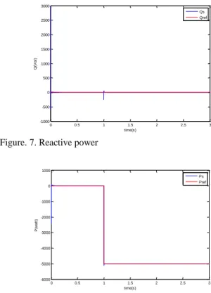
The above figures show the performance of the vector control and reactive power in the stator applied to a doubly fed induction machine. 0 0.5 1 1.5 2 2.5 3 -1000 -500 0 500 1000 1500 2000 2500 3000 time(s) Q (V a r) Qs Qref
Figure. 7. Reactive power
0 0.5 1 1.5 2 2.5 3 -6000 -5000 -4000 -3000 -2000 -1000 0 1000 time(s) P (w a tt ) Ps Pref
Figure. 8. Active power
Note that the active and reactive and current (ird, irq) are identified with their references powers.
0 0.5 1 1.5 2 2.5 3 0 2 4 6 8 10 12 14 16 18 time(s) id r( A ) Idr Idrref
Figure. 9. Direct current of the rotor
0 0.5 1 1.5 2 2.5 3 -25 -20 -15 -10 -5 0 5 10 15 20 time(s) iq r( A ) Iqr Iqrref
Proportionality appears between the rotor current quadrature Iqr and active power, and between direct current Idr and reactive power.
0 0.5 1 1.5 2 2.5 3 -2.5 -2 -1.5 -1 -0.5 0 time(s) fl u d s (W b )
Figure.11. Direct flux of the stator
0 0.5 1 1.5 2 2.5 3 -1.5 -1 -0.5 0 0.5 1 time(s) fl u q s (W b )
Figure. 12. Quadrature flux of the stator
The quadrature component of flux is almost zero in steady state, which confirms the hypothesis of the vector control. Note the effect of coupling between the two powers P and Q, because that Pref pass (0 to -800) to (t = 1s) there is a small oscillation in the graph of the power Q.
0 0.5 1 1.5 2 2.5 3 -20 -10 0 10 20 30 40 time(s) c e m (N .m )
Figure. 13. Electromagnetic torque
Note that the electromagnetic torque reacts spontaneously when there is a demand for active power, reactive power independent.
VIII. CONCLUSION
This paper presents a study of variation of integration with a variable speed wind turbine connected in the grid.
In order to investigate the models and methods for the wind turbines system with DFIG, some methods to improve the control of filed oriented are presented.
Using simulations under Matlab-Simulink environment, it has been found that, with the DFIG. The application of the proposed model demonstrates the effect of the control on the grid. Using this model, it is possible to estimate the dynamic characteristics of power system stability. All these observations underline the importance of tool for integration of the wind turbine in power system.
Moreover, for future work, the transient stability of the multi-machine power system including wind farms combined with this model to improve the power system stability should be studied.
REFERENCES
[
1] Claudio L.Souza et. al., “Power System Transient Stability Analysis including Synchronous and Induction Generator,” IEEE Porto Power Tech Proceedings, Vol.2, pp.6, 2001[2] J. L. Rodriguez-Amenedo, “Automatic Generation Control of a Wind Farm With Variable Speed Wind Turbines,” IEEE Transactions on Energy Conversion, Vol 17, No. 2, June 2002.
[3] J. G. Slootweg, S. W. H. de Haan, H. Polinder, W. L. Kling, “Aggregated Modelling of Wind Parks with Variable Speed Wind Turbines in Power System Dynamics Simulations,” Proceedings of the 14th Power Systems Computation Conference, Sevilla, 2002. [4] S. Stapelton and George Rizopoulos, “Dynamic
Modelling of Modern Wind Turbine Generators and Stability Assessment of On- and Off-Shore Wind Farms” Proceedings of the 3rd MED POWER Conference, 2002. [5] S. Seman, F. Iov, J. Niiranen, and A. Arkkio, “Advanced modeling of doubly fed induction generator wind turbine under network disturbance,” in Proc. 5th Int. Workshop Large-Scale Integration WindPower Transmission Networks Offshore Wind Farms, Glasgow, U.K., Apr. 7– 8, 2005, pp. 305–314.
[6] J. B. Ekanayake, L. Holdsworth, X. G. Wu, and N. Jenkins, “Dynamic modeling of doubly fed induction generator wind turbines,” IEEE Trans. Power Syst., vol. 18, no. 2, pp. 803–809, May 2003.
[7] A. Tapia, G. Tapia, J. X. Ostolaza, and J. R. Saenz, “Modeling and control of a wind turbine driven doubly fed induction generator,” IEEE Trans. Energy Convers., vol. 18, no. 2, pp. 194–204, Jun. 2003.
[8] M. Hogdahl and J. G. Nielsen, “Modeling of the Vestas V80 VCS wind turbine with low voltage ride-through,” in Proc. 5th Int.Workshop Large-Scale Integration Wind
Power Transmission Networks Offshore Wind Farms, Glasgow, U.K., Apr. 7–8, 2005, pp. 292–304.
[9] J. Morren and S. W. H. de Haan, “Ridethrough of wind turbines with doubly-fed induction generator during a voltage dip,” IEEE Trans. Energy Convers., vol. 20, no. 2, pp. 435–441, Jun. 2005.
[10] T. Petru and T. Thiringer, “Modeling of wind turbines for power system studies,” IEEE Trans. Power Syst., vol. 17, no. 4, pp. 1132–1139, Nov. 2002.
[11] S. Seman, S. Kanerva, J. Niiranen, and A. Arkkio, “Transient analysis of wind power doubly fed induction generator using coupled field circuit model,” presented at the Int. Conf. ICEM, Cracow, Poland, 2004, unpublished.
[12] Sorensen, P., Hansen, A.D., Rosas, P.A.C. – Wind models for simulation of power fluctuations from wind farms, Journal of Wind Engineering, 90, 2002, pp.
1381-1402.
[13] Shaltout, A. - Analysis of torsional torques in starting of large squirrel cage induction motors IEEE Trans. on Energy Conversion, Vol. 9, No. 1. March 1994, pp. 135-141.