Design and Prototyping of a Retrofittable Motorized Module for Hand Powered Tricycles for Developing Countries
by
Nathan Philip Wang
SUBMITTED TO THE DEPARTMENT OF MECHANICAL ENGINEERING IN PARTIAL FULFILLMENT OF THE REQUIREMENTS FOR THE DEGREE OF
BACHELOR OF SCIENCE IN ENGINEERING AT THE
MASSACHUSETTS INSTITUTE OF TECHNOLOGY
JUNE 2008
©2008 Nathan Wang. All rights reserved.
The author hereby grants to MIT permission to reproduce and to distribute publicly paper and electronic copies of this thesis document in whole or in part
in any medium now known or hereafter created.
Signature of
Author:--'9 Department of Mechanical Engineering
May 9, 2008 Certified by:
Anette E Hosoi Associate Professor of Mechanical Engineering Thesis Supervisor Accepted by:
John H. Lienhard V essor of Mechanical Engineering Jndergraduate Thesis Committee
Design and Prototyping of a Retrofittable Motorized Module for Hand Powered Tricycles for Developing Countries
by
Nathan Philip Wang
Submitted to the Department of Mechanical Engineering on May 9, 2008 in partial fulfillment of the
requirements for the Degree of Bachelor of Science in Engineering as recommended by the Department of Mechanical Engineering
ABSTRACT
Current wheelchair designs in developing countries create many difficulties for their users. In Kenya, wheelchair users are often unable to use public transportation, and thus are isolated and usually without work. This thesis outlines a feasible design for a retrofittable motorized module for a hand-powered tricycle produced and widely distributed throughout Kenya. There are many mobility aids that are similar to the Kenyan handcycle, which can also adapt the module design. By using this innovative module, users will be able to increase their range of travel and access areas where human-powered transport is not sufficient. This simple addition will improve the quality of life for the physically disabled user. This work will be presented to a wheelchair workshop summer 2008 in hopes to convert it into a feasible design for production. Increased reliable mobility will allow the disabled community in Kenya to apply for jobs, and even be afforded opportunities in micro-business for the first time.
The design of the powertrain consists of a common motorized bicycle 2 hp engine and a two-stage gear reduction. The control system uses an analogous setup to that of a motorcycle. This control system is integrated into the layout of the chair. Three operation modes are possible with this design: hand-powered only, engine-powered only, or hand-powered with motor-assist.
Thesis Supervisor: Prof. Anette E. Hosoi Title: Professor of Mechanical Engineering
TABLE OF CONTENTS
A B STR A C T ... 2 1. INTRODUCTION ... 4 1.1 M OTIVATION ... 5 2. D ESIG N C R ITER IA ... 6 2.1 PERFORMANCE REQUIREMENTS ... 6 2.2 M OTOR A SSIST... 6 2.3 RETROFITTABLE ... 62.4 "U RBAN-M ODE" ... 7
2.5 SUM M ARY OF D ESIGN CRITERIA ... 7
3. DESIGN CONSTRAINTS AND FREEDOMS ... 7
3.1 M ATERIAL CONSTRAINTS ... 8
3.2 MANUFACTURING CONSTRAINTS ... 8
3.3 ENGINE SELECTION CONSTRAINTS ... 8
4. A N A LY SIS ... ... 9
4.1 CURRENT DESIGN A NALYSIS ... 9
4.2 PERFORM ANCE CALCULATIONS ... 9
5. M A TE R IA L SELE C TIO N ... 10
5.1 ENGINE SPECIFICATIONS... ... ... . ... 10
5.2 STEEL AND BICYCLE PARTS SELECTION ... ... . . ... 11
6. ENGINE AND DRIVETRAIN DESIGN ... 11
6.1 M OTOR CHASSIS AND PLACEM ENT ... ... 11
6.2 TW O-STAGE G EAR REDUCTION ... ... ... . 12
6.3 CONTROLS ... ... ... . 13
6.4 M ATERIAL COSTS ... ... .. 15
7. RESULTS AND RECOMMENDATIONS ... ... 15
1. INTRODUCTION
Twenty million people in developing countries are in need of a wheelchair, but less than 2% of these people actually have access to a functional mobility aid [3]. Further, individuals who do obtain a wheelchair (after taking out a micro-loan or receiving donations) often obtain one that is not sufficient for the terrain and conditions in which they live. The majority of these wheelchairs are donated by western countries and thus are made in a Western style. These chairs are not equipped for developing countries because they were designed with a very different user in mind: one who would only use the chair on smoothly paved sidewalks, and to go short distances. Traditional western wheelchairs are under-engineered for the rugged dirt roads, rain and muddy conditions common in developing countries. Appropriate
wheelchair technology for the developing world must be designed for the specific needs and conditions of its customers. There are a few companies within the developing world that are currently trying to produce suitable wheelchairs. The ones that do exist tend to be small and less technically equipped than their western counterparts. Lack of funding, as well as limited access to technology and materials common to the developed world, puts these developing manufacturers at a disadvantage. This is mostly due to their slower output, higher prices, and less publicity. Oftentimes, although they are able to produce a more appropriate, user-friendly chair for their customers, they cannot sell it due to the aforementioned problems.
Figure 1: A common donated western wheelchair to developing countries. Nicknamed the "white plague" by many local manufacturers, due to its lack of padding (which causes pressure sores) and poor durability.
Several wheelchair workshops, such as that owned by the Association for the Physically Disabled in Kenya (APDK), have attempted to tackle this challenge by creating a mobility aid that is easily reparable and has a rugged construction. Rather than a traditional
wheelchair, this workshop created a hand tricycle better suited for difficult terrain. The hand cycling method is advantageous over the traditional wheelchair propulsion motion of
awkward sideways push of the wheels because it can produce a much more powerful stroke to the. The power output of the hand tricycle is increased additionally because there is the
added benefit of a gear train similar to that of a bicycle [2]. An added benefit is that the hand tricycle is made from commonly used steel pipe and bicycle parts, which allows the
workshop to service all these chairs locally.
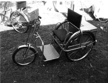
Figure 2: Hand-cycle wheelchair made by APDK.
Although the hand-powered tricycle offers many advantages over the traditional western wheelchair, it does not put its users on an equal playing field with non-handicapped people; public transportation is not available to tricycle users because the size of the device makes it impossible to board a public van or bus. At APDK, director Hubert Seifert, an expert in the needs of wheelchair users and the economic stability of local workshops in developing countries, has identified the need for a motorized version of the tricycle mobility aid to combat this problem.
1.1 MOTIVATION
It has been one of Hubert Seifert's visions to create a wheelchair with the capability to be used in place of public transportation. In January 2005, APDK attempted to develop a handcycle with an electric motor in the front hub. Unfortunately, the prototype that the workshop designed is facing an immense amount of challenges, making the motorized version hard to implement and impossible to mass manufacture due to the inability to solve the problems at a prototyping level. Today, this prototype has shown little promise of working, and a better design needs to be implemented. Seifert sought further development of this wheelchair to be produced at MIT, identifying it as a project that would have immense impact on people with disabilities [4]
A motorized handcycle will create a plethora of opportunities for the user. Since public transportation is often not an option, this new mobility aid will allow the user to extend their range of travel. This greater range will create more opportunities for the people with
tricycle will fill the void caused by the limitations of human power- when hills are steep or the user is carrying a large load, a motor assist can make former barriers surmountable. With
a motor the users can carry larger loads and start businesses where their physical disabilities do not pose a difficulty to transporting goods. In addition to these added benefits, the mobility aid will not hinder the functionality of the original tricycle design, so when the user does not need the motorized feature, they can simply turn it off, and go about their normal lifestyle. In this way, the motorized tricycle will only improve their everyday life.
2. DESIGN CRITERIA
The design requirements necessary for this project were defined to meet user needs. APDK, the wheelchair manufacturer, was able to communicate what the user should be able to obtain
if he used this motorized module. From these needs, a quantitative requirement was derived to measure the success of the final design.
2.1 PERFORMANCE REQUIREMENTS
In order to be an adequate replacement for public transportation, the engine module must
provide enough power for the user to travel an extended distance at a relatively fast speed.
The terrain and conditions in Kenya create a challenge in the ability to travel. In order to
allow the user to travel at speeds similar to the ones obtained by public transportation or
other motor vehicles, the engine module must be able to allow the user to travel at least
1 lm/s
(25
mph) over rough terrain. The engine must also allow the user to surmount
obstacles that they are unable to overcome otherwise. Most obstacles come in the form of
hills, and in general they have a slope of less than 10%. The design of this product therefore
requires that the user maintain a speed of 1 lm/s going over a grade of 10%.
2.2 MOTOR ASSIST
In the final design, in order to overcome the largest obstacles, the motor and the user's hand
power can be used simultaneously. While the motor supplies 1491 Watts of power, the
added 60 Watts of power, from the user to the powertrain, will increase the performance of
the wheelchair as well allowing the user to get more mileage per gallon out of their system.
More importantly, the user can produce torque from a rest or low speeds. This will be the
most beneficial when traveling through conditions where high torque at low speeds is
necessary, like unpaved roads or mud.
The motor assist, however, provides some interesting human design factors design in order to
make the system intuitive and comfortable. Since the person must reach an initial velocity
and engage the clutch, in order to start the motor via a capacitor discharged ignition magneto,
the controls must be easy to use while pedaling.
In order to widely spread this new concept, the power module needs to be fully retrofittable to the current tricycle designs produced by APDK. This will allow every user of the hand-trike to take advantage of the engine module, even those who have a previous version of the hand-trike. The design will therefore spread faster to allow more people to gain the
opportunities that this innovation can offer. This also does not require the manufacturer to change their current wheelchair design and can therefore keep all the jigs, tooling, and manufacturing processes the same. This will significantly cut down on costs in terms of training to build a new product.
2.4 "URBAN-MODE"
The wheelchair does not need to run off of the motor at all times. In certain urban areas, for example, this could prove to be dangerous to both the user and the pedestrians' safety. Also, at times the user might not need to use the engine because they want to travel slower, have a conversation with a pedestrian, or want to operate quieter for a variety of reasons. Therefore, it is necessary that the motor can be disengaged and shutoff, while not interfering with the hand-powered portion of the chair. In this way, the user can use hand-power in certain heavily crowded urban settings (or if they run out of gas), and use the motorized setting for long distance travel.
2.5 SUMMARY OF DESIGN CRITERIA
Table 1 shows the user needs and the subsequent design requirements that are outlined above.
USER NEED DESIGN REQUIREMENTS
1) Ability to quickly over rough terrain to compete 1) Travel 1 lm/s (25mph) on gravel or dirt with public transportation
2) Overcome large physical obstacles 2) Ability to scale a grade 10 hill
3) Motor-Assist to normal hand powered use 3) Controls that allow the user to pedal normally while still operating the motor easily.
4) Retrofittable to current hand-trike designs 4) Design that does not change the wheelchair and can be installed on any model of the hand-trike 5) Ability to operate the chair without the motor in 5) Motor can be disengaged or bypassed
an urban setting
Table 1: Overview of User Need and Subsequent Design Criteria
3.
DESIGN CONSTRAINTS AND FREEDOMSThe manufacturing of the design in a developing country creates a certain environment that one must keep in mind when designing a product. When designing this power module, currently available parts, materials, and manufacturing were all considered. Under certain
conditions, design constraints limit the project and make the solution very difficult to
implement. For example, without the use of modem precision tools, the end product must be robust, and allow for a large range of tolerances in all the parts. There are also some
freedoms to designing for this particular workshop in Kenya. Although CNC is not
available, simple machining in-house is, and there is the option of outsourcing more complex projects. TIG and MIG welding are commonly used, and labor cost is low all around. Other freedoms that played into this design include the wide availability of bicycle parts, and a specific engine that is already available. In order to make this project feasible and useful, the prototype had to be designed and assembled with the same materials and manufacturing techniques as those that will be used in the final product.
3.1 MATERIAL CONSTRAINTS
The primary design constraint in the prototyping of the engine module was the limitation of the types of materials available in developing countries to manufacture the system. The material selection in the developing world limits the design freedoms that could have been taken in creating a functional prototype. When building this chair, the design was
constrained to locally available bicycle parts and mild steel (1018 - 1020) pipe. Bicycle parts are commonly used to make components of the trike, such as the front fork and axles. In addition to the availability of these products, these parts are inexpensive and easily machined by the methods available. The system could have simply been created using modem powertrain components found in consumer products such as mopeds and motorcycles, however due to their high cost and low availability, the final design used bicycle parts which are cheap, repairable, and available everywhere. The bicycle
components and the pipe that was readily available were made from steel. Conveniently, the chassis for the engine was made from the same size pipe as the rest of the frame, making the material familiar to the manufacturers.
3.2 MANUFACTURING CONSTRAINTS
Secondly, the machining processes used to create the wheelchair require large tolerances and must account for error in part production and manufacturing. In order to keep costs low, all part making and assemblies are done in house. The main form of joining metal is TIG and MIG welding, and the entire system is required to be assembled by hand. Machining bike parts to fit the assembly was required to be done with a simple bandsaw or hacksaw. While precision-engineering techniques may be available by outsourcing the work, the costs of manufacturing would raise substantially if these techniques were used.
3.3 ENGINE SELECTION CONSTRAINTS
Lastly, the engine selection was very limited. Ultimately, APDK selected an engine that was widely distributed in the area. Fortunately, the engine specifications of the selected motor met the user need. Only after careful consideration and bench level calculations was this engine deemed appropriate for use.
4.
ANALYSIS
4.1
CURRENT DESIGN ANALYSISThe current design for the hand-trike allows for the placement of the motor to be in a multitude of locations. The frame is made almost entirely out of one inch diameter 2mm
thickness steel pipe. The wheels and hand-pedaled power system are all made from bicycle parts. Dynamic analysis was done briefly on the wheelchair to determine if the motor
module could merely drive one wheel and still allow for fairly straight driving. By only driving only the rear left wheel and assuming that the other axle was frictionless, the mobility aid will only rotate left of right if the front wheel skids upon the ground. By driving only one wheel, the mobility aid then depends on the coefficient of friction between the ground and the front wheel to avoid inadvertent turning. The outcome of this dynamic analysis was positive; it showed that it was not necessary to connect the two rear wheels via a shaft to get straight driving, and that having the motor module drive only one wheel would be sufficient. Further testing with the actual motorized unit also showed the same result: applying power to only one of the rear wheels can propel the unit forward without any significant variation in direction.
4.2 PERFORMANCE CALCULATIONS
The most important step in determining the feasibility of this project was calculating the power requirements and the gearing of the engine and the powertrain. In order to calculate the power necessary to drive the chair, a basic power analysis was done. The frontal area of the wheelchair was estimated and common drag coefficient was used. From here, the design requirements were added into the calculation. As seen in Figure 3 and 4, when the forces are calculated in order to have a constant velocity of 1 lm/s, the horsepower required to meet the design parameters was 2.02 hp.
Fw
Figure 3: Free Body Diagram showing forces
Assumptions
Frontal Area = A = 1.0 m2 Drag Coefficient = c, = 1.0 Velocity = v = 11 m/s (25mph)
Weight of User and Mobility Aid = w = 100 kg Constants and Given Requirements
Gravitational Constant = g = 9.8m/s2 Air Density = p = 1.226 kg/nm2 Coefficient of Rolling Resistance =
Steepest Grade of Hill = d = .05
C• = .008
Calculations
Wind Resistance = Fw = .5A c, p v2
Rolling Resistance = Frl = w g crr
Gravitational Resistance = Fg = w g d
Total Resistance = F= = Fw+ F Fri+ Fg 131.013 kg/m2
Power Needed = Fv= 1441.143 Watts = 1.93hp
Power Required= efficiency* Fv = 1.05*1.93 = 2.02hp
Figure 4: Power Calculation
5. MATERIAL SELECTION
The materials that were used to make the powertrain of the wheelchair are a combination of "off-the-shelf' bicycle parts, steel tubing, and a common bicycle motor. All these materials are commonly found in developing countries in order to ensure manufacturing feasibility in Kenya.
5.1
ENGINE SPECIFICATIONS
The engine selected is a Grubee Skyhawk 48cc engine that runs at 2.0 hp [1], slightly less powerful than the specification needed, as calculated in Figure 4. It is a petrol two-stroke,
single cylinder, air-cooled engine with a capacitor-discharged ignition. The engine is rated to carry 90 kg (198 lbs) at 60 km/h (38mph). The motor outputs power via a spur gear that is
connected to a bike chain. The motor has a nominally-on friction clutch and a twist handle throttle. For the purposes of this project, the twist handle has been replaced by a bicycle handbrake in order meet the motor-assist design criteria.
Figure 6: Front View of Engine
This motor is most commonly used as an attachment to a bicycle. The optimal gear ratio is 1:6 for a bicycle. Since a bike and its rider are estimated to be about 80 kg, which is 20 kg less than a hand-trike and its user. To account for this slight difference in weight, another reduction must be put in to increase torque. Although this design sacrifices speed, the current motor specifies that it can run up to 38 mph on a bicycle with the 1:6 gear ratio at 2 hp. The motor, therefore, runs at about 3120 rpm at peak power to produce this kind of
speed. Therefore, by taking in account the rpm and the power output, in order to produce speeds of 25 mph to remain within the design requirements, a gear reduction of 2:3 should be used. This was the reduction used in all testing of the prototype.
5.2 STEEL AND BICYCLE PARTS SELECTION
The steel used to make the powertrain is completely made of 1" OD, 2mm Wall Tube steel tubing, the same material as the rest of the mobility aid. The bicycle parts that are prevalent are the Avon Front fork, a common front bearing, and a freewheel.
6.
ENGINE AND DRIVETRAIN DESIGN
6.1
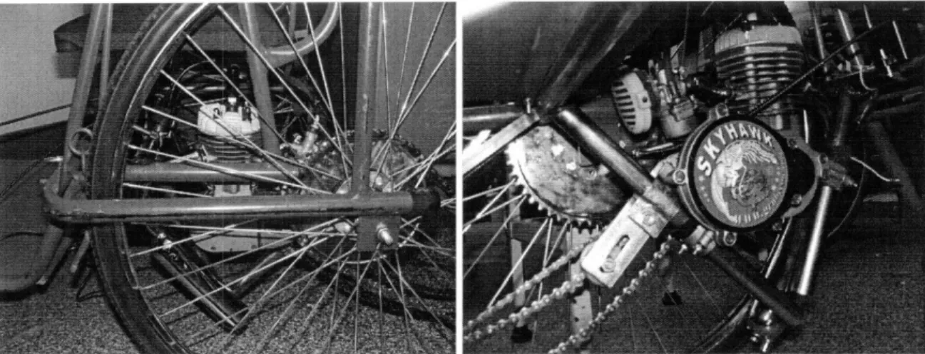
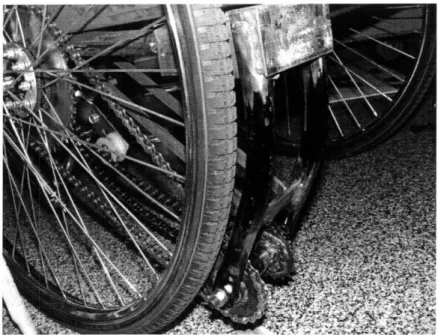
MOTOR CHASSIS AND PLACEMENTThe main criterion used when selecting the placement of the frame to hold the motor (the chassis) was the ultimate location of the motor and its ease of installation. The motor's placement is inconspicuous and the assembly is simple. The entire structure has been made from four steel pipes, and the motor is located directly under the seat of the wheelchair. Not only does this hide the motor to deter theft, it also allows somewhat simple alignment of the motor with the wheel via the two-stage reduction. The placement of the motor under the seat permits quick maintenance of the motor from the seated position as well. The user can adjust the choke and prime the engine right from where they are. The user can also check the connections of the motor with the throttle and clutch. Finally, this placement ensures the closeness of the gas tank, which makes it easy and convenient to fill.
Figure 8: Two views of the motor assembly. The first shows the ability of the wheel to
hide the motor, in order to deter theft. The second picture more closely shows the assembly and frame that the engine sits on.
6.2
Two-STAGE GEAR REDUCTIONThe two-stage gear reduction couples the motor to one of the rear wheels. The reduction is made from a readily available front fork, and a front axle. It is necessary, because
unfortunately the optimal gear ratio for the motor cannot be made using a common bicycle sprocket, and so attaching the motor directly to a rear wheel is not an option. By using gear reduction, a combination of available sprockets can be assembled that best creates the optimal gear ratio.
The two-stage gear reduction shown in Figure 8 is made of a bicycle front fork, a front hub, bike chains, and two sprockets from a bicycle freewheel. It is mounted to the frame using angle iron and steel gussets. All these parts and materials are readily available in developing countries.
Figure 8: Two-stage gear reduction. This figure shows the
relative placement of the gear reduction in respect to the motor. The arrows show the relative motions of the chains.
Since the motor is geared down in two stages, a more complex combination of sprocket sizes can be used, which makes it simpler to reach the ideal gear ratio. This current design has a gear reduction of 3:4, which will be discussed in the Results section of this paper.
The two-stage gear reduction serves two purposes. First and foremost, it produces a greater torque at the wheel. This makes it possible to meet the design specification of 1 lm/s (25mph)
up a hill with a 10% grade. In addition, different gearing may be needed in extreme
conditions. For example, by using the reduction, one can prepare the trike for the muddiest of conditions. The versatility of this system permits powered transportation in every circumstance. The current design places the two-stage reduction at an easily accessible location, so that, if necessary, this gear can be replaced or switched with a gear reduction that more suitably matches the task or conditions at hand.
Figure 9: Two-stage gear reduction- external view. The
reduction lies very close to the rear wheel in order to minimize the chain length and avoid derailing.
The two-stage reduction also allowed for a slight alteration of the geometry between the motor and the wheel that it drives. Traditionally, the motor is placed in line with the wheel. However, in the case of the APDK hand-trike, this was not a feasible option. The motor could neither be placed in the leg rest area nor directly behind the seat due to the physical harm it would cause the rider, and the inaccessibility of the motor from the seated position (which is necessary for maintenance purposes). Mechanically, these locations are not optimal, either. This is because placing the motor in the rear of the chair would require a structural element that is completely separate from the main frame of the chair.
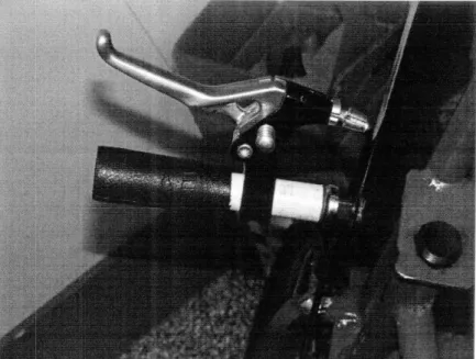
6.3
CONTROLS
The controls were placed strategically to ensure that the user could both operate the motor and pedal simultaneously. By placing the clutch and the throttle on the hand pedals, the user can use the chair in three ways: hand power only, motor power only, or hand power with motor assist. Concerns with this design are that the clutch and throttle are slightly
cumbersome to use while pedaling, and the handlebars of the hand-trike must be extended slightly to allow freer movement of the cables.
The clutch and the throttle are located in the normal motorcycle fashion: the clutch is on the left and the throttle is on the right. They both actuate their given mechanisms through a cable system, much like a hand brake.
Figure 10: Prototype of clutch and throttle controls. Retrofitted to a bicycle handbrake, these allow easy access to the controls while pedaling.
The designed placement is also ideal for the start-up of the motor. The motor is turned on through a magneto system, which requires that the piston be manually actuated to help initiate the cycle. As a result, the wheelchair must be in motion when starting. The clutch is engaged slowly, engaging the motor, and starting the cycle. Since the controls must be operated during this procedure, the current setup provides an interface that allows the rider to operate the correct mechanisms to make start-up possible.
As a countermeasure, a stationary bar with the clutch and throttle has been designed,
although not prototyped. The countermeasure does not allow the simultaneous operation of the throttle and the hand pedals, and thus does not permit the "motor-assisted" option. However, this tradeoff may have to be made depending on the cost and durability of the cable system. This is uncertain because these cables are meant to be in a stationary position, but they are moving with the hand pedals in this design. The cables turning with the hand pedals could put unnecessary stress on the part, causing premature breakage.
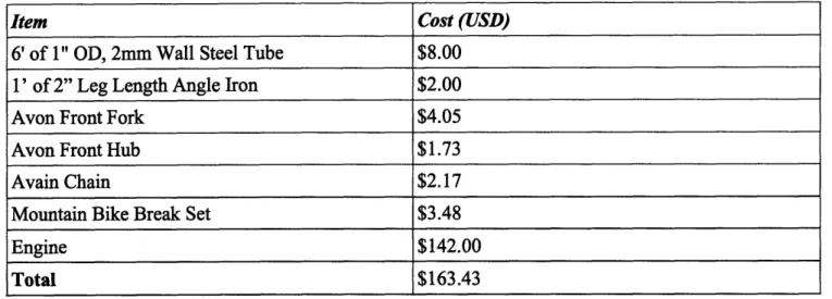
6.4 MATERIAL COSTS
The total cost of the additional engine module is shown in the table below.
Item Cost (USD)
6' of 1" OD, 2mm Wall Steel Tube $8.00 1' of 2" Leg Length Angle Iron $2.00
Avon Front Fork $4.05
Avon Front Hub $1.73
Avain Chain $2.17
Mountain Bike Break Set $3.48
Engine $142.00
Total $163.43
Table 2: Material Costs
7. RESULTS AND RECOMMENDATIONS
During initial testing of the prototype, it was determined that the current prototype is a feasible proof of concept that can be adapted to the current production of hand-trike
wheelchairs. The current gear reduction is at the lower bound of reductions, well suited for speed over a level ground. When testing the assembly, a top speed of 9.5 m/s was obtained. The tested speed is slightly less than the desired top speed, but still a significantly greater than a handcycle without a motorized attachment.
When approaching top speed, the handcycle starts to experience speed oscillations. In order to avoid these oscillations, a greater gear reduction should be used in order to slow the output speed. Although this brings the wheelchair farther away from its design criteria, the sacrifice of speed for the safety and longevity of the handcycles is more beneficial for the user. This will also increase the torque that the wheel outputs, which will be beneficial to the user. This lower bound is beneficial for the next round of prototyping, as the results from this testing shows the limits of the mobility aid, which have not been explored before.
There are a few modifications that need to be made to the engine module in order to move from a prototype to a more robust manufactured product. This prototype was an excellent proof-of-concept, as it shows that the design is feasible, however most of the modifications need further testing in Kenya to ensure that the terrain and conditions can be met by the design. Numerous gear reduction ratios should be tested over native terrain and weather conditions. User testing should also be implemented in order to gain feedback on the control setup.
The engine module needs a more robust form of manufacturing. The process to align the motor with the two-stage reduction, and subsequently, to the rear wheel was incredibly difficult. A derailleur should definitely be implemented between the motor and gear
reduction. This will ensure the tension in the chain is kept, despite the high torque produced by the motor. The derailleur will also serve as a guide for the chain to remove uncertainty in its movement from the motor to the gear reduction. In this way, the chain will definitely be more secure and robust.
Currently, the motor selected starts only if you start the stroke cycle manually by riding the handcycle. Another possible investment would be a pull-start motor attachment to the current motor. In order to create a better, more intuitive, control setup the clutch and throttle should be removed from the hand pedals. If the motor is started remotely, instead of through manually moving the piston by pedaling the hand-trike, the controls can be moved from the hand pedals. This will increase the life of the cables that control the clutch and throttle. Also, an idler gear can be put on the two-stage reduction, so the clutch will not be necessary to engage and disengage constantly. This way, the two-handbrake design (one for clutch and the other for throttle) can be controlled with only the throttle. The clutch does not have to be disengaged to go into the "hand-pedaling only" mode, because the idler will allow rotation of the wheel without driving the engine. This design will be much more intuitive and safe. Overall, this design has great potential to possibly help increase mobility of many of its users. The opportunities that this design will ultimately bring to its user make pursuing this project further to manufacturing very worthwhile.
8.
REFERENCES
1. Grubee, Inc. Skyhawk Standard Lever Clutch Series Manual. China Gas. Rev. June 01, 2005.
2. Haisma, J.A., van der Woude, L.H., Stam, H.J., Bergen, M.P., Sluis, T.A. & Bussmann, J.B. Physical capacity in wheelchair-dependent persons with a spinal
cord injury: a critical review of the literature. Spinal Cord 2006.
3. International Society of Prosthetics and Orthotics. Wheelchairs. http://www.ispo.ws/. 4. Seifert, Hubert. Personal conversation with Nathan Wang. September 24, 2007.