i -. c A '~·· ,_ .
DEIONIZATION MEASUREMENTS
OF GRID-CONTROLLED THYRATRONS
FRANK
M.
VERZUH
TECHNICAL REPORT NO. 101
MARCH 8, 1949
RESEARCH LABORATORY OF ELECTRONICS
The research reported in this document was made possible through support extended the Massachusetts Institute of Tech-nology, Research Laboratory of Electronics, jointly by the Army Signal Corps, the Navy Department (Office of Naval Research) and the Air Force (Air Materiel Command), under Signal Corps Contract No. W36-039-sc-32037, Project No. 102B; Department of the Army Project No. 3-99-10-022.
MASSACHUSETTS INSTITUTE OF TECHNOLOGY Research Laboratory of Electronics
Technical Report No. 101 March 8, 1949
DEIONIZATION MEASUREMENTS OF GRID-CONTROLLED THYRATRONS Frank M. Verzuh
Abstract
This paper describes a method of evaluating the deionization time of thyratrons by means of an accurately calibrated time sweep. The apparatus permits precise control of each of the pertinent parameters, such as the amplitude and duration of the currents and voltages during the conduction
and post-conduction periods. The effect of the nature of the enclosed gas
upon the deionization time is presented by a study of thyratrons containing
argon, hydrogen, mercury vapor and xenon gas as the active elements. The
individual effects of each of the parameters in the tube and of the associ-ated tube circuit are illustrassoci-ated by suitable graphical plots. Finally, the relative merits of many commercial tubes operating under typical dynamic conditions are summarized by comparative graphs which illustrate the corre-sponding deionization times.
DEIONIZATION MEASUREMENTS OF GRID-CONTROLLED THYRATRONS I. Introduction
Deionization time is defined as the length of time from the cessation of the anode current in a thyratron until sufficient recombination and dif-fusion of the ions and electrons has occurred to permit the grid to regain control. This period of time is influenced by such factors as the applied negative grid voltage, the grid circuit parameters, the anode current, the anode voltage, the nature of the enclosed gas, the gas pressure and the
electrode dimensions and orientation. Furthermore, this time is also strongly influenced by the rate of rise of the reapplied anode voltage.
A capacitor-discharge circuit is used in the conventional methods of
measurement of deionization time (1). Such a circuit assumes a constant
reignition voltage, is a function of the discharge capacitor, ignores positive-ion current and requires numerical computation for the evaluation of the deionization time. In this type of circuit, the rate of rise of the reapplied anode voltage is not a constant but is a function of the
discharge parameters. Obviously, such a method of measurement is not quite
satisfactory.
Since the deionization time varies with many parameters, it is essential to know the exact conditions under which the measurements are made. There-fore, successive tests, under identical conditions in which only one para-meter is changed, are necessary for correct interpretation of this parapara-meter
variation. In making these tests the method of measurement must be a rapid one,as the number of parameters is large.
II. Experimental Apparatus and Method of Measurement
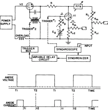
A circuit diagram illustrating the layout of electrical equipment and the anode voltage and current waveforms of the test thyratron V1 is shown in Figure 1. The deionization time is defined as the time interval between
the cessation of anode current at t and the minimum time t2 at which the
anode voltage may be reapplied to V1 without its going into continual con-duction.
In this circuit the synchronizer controls the sequence of all opera-tions. Trigger T, supplied by the Model 5 synchroscope, fires the thyra-tron V1 and initiates the discharge of a current pulse, the duration of which is determined by the pulse-forming network (hereafter referred to as
the PFN) (2). The anode voltage during the current pulse is a
constant-amplitude, negative or positive voltage determined by the impedance match between the PFN and the load resistance RL. The anode voltage remains at this constant value until some specified time later when the variable-delay
-1-Fig. 1 Circuit diagram of connections used in measurements.
ANODE VOLTAGE
TI T2 TI T2 TIME
-ANODE -I
It1 1t2 Itl It2 TIME
trigger T2 fires the charging thyratron V2. The PFN then charges up to the supply potential in a minimum time equal to the pulse duration of the PFN. If the time interval between the extinction of the arc and the reapplication of the anode voltage is long enough, V1 is sufficiently deionized to permit
the grid to regain control. If this time interval is less than that required
for deionization, however, the tube goes into continual conduction.
A visual determination of the deionization time is obtained by
view-ing the anode-cathode voltage with the synchroscope. The deionization time
is thus obtained directly from the accurately calibrated scale of the hori-zontal sweep of the synchroscope (3).
The synchronizer (as shown in Figure 1) provides two initiating
trig-gers: a fixed-delay trigger which starts the linear sweep of the CR tube,
and a variable-delay trigger which may be retarded as much as 1200
micro-seconds by the variable-delay circuit. This second trigger fires V2 via
the pulse-shaping trigger box.
A pulse-forming network is used in this investigation for several
reasons: (a) it provides an accurate control of the duration of the current
pulse; (b) it permits a suitable adjustment of the degree of mismatch be-tween the PFN and its associated non-inductive load, and provides a means for controlling the anode voltage during the post-conduction period; (c) it insures a constant rate of reapplication of the anode voltage, and (d) it permits measurement of the deionization time of hydrogen thyratrons under dynamic conditions which are identical with those employed in radar line-type modulators.
-2-r
---The deionization measurements are obtained in the following way. 1. A constant-temperature oil bath is used to insure constant
gas pressure.
2. The PFN impedance and the load impedance are adjusted to provide the desired anode voltage during the post-conduction period.
3. The supply voltage is adjusted to provide the selected value of arc current.
4. The grid circuit parameter is assigned.
5. The value of deionization time is measured for various values of applied grid voltage.
A curve which relates the deionization time and the applied grid voltage is
therefore obtained. The magnitude of one of the variables, e.g., Rg, is
then changed by a desired amount and the process is repeated. Thus a family of curves is attained with one of the variables as a parameter.
III. Deionization Time of the Hydrogen Thyratrons
In this investigation, thyratrons containing argon, hydrogen, mercury
vapor and xenon gas were tested. Of these, the hydrogen thyratron had the
shortest deionization time. Pure hydrogen has a high electron mobility and
a low ionization. These properties were advantageous in the construction of
switching devices for radar application and resulted in the development of one hydrogen thyratron.*
In order to permit a direct comparison of the effects of the different factors upon the deionization time, the same 3C45 hydrogen thyratron was
tested under a number of only slightly different conditions. The effect of
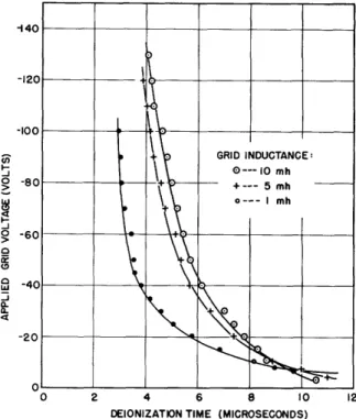
grid resistance upon the deionization time is illustrated in Figure 2. The large values of grid resistance limit the positive-ion current flow from the grid-cathode region during the post-conduction period. A further reduc-tion.in deionization time is effected by the use of the proper value of grid inductance, as shown in Figure 3. A large grid bias and a low grid impedance provide a large inverse grid current and a low deionization time. Corresponding to the grid inductance of 1, 5, and 10 mh, the maximum grid
currents are 180, 75 and 50 ma, respectively. It is evident, therefore,
that a compromise is necessary between the maximum allowable grid current and the minimum deionization time.
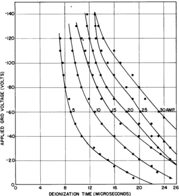
The effect of the anode current upon the deionization time is shown in Figure 4. As the arc current is increased, the positive-ion concentra-tion is increased, with a resulting increase in the deionizaconcentra-tion time.
Although the presence of a negative voltage at the anode during the * K. J. Germeshausen of M.I.T. is largely responsible for the design and
development of the hydrogen thyratrons.
--'30 U I-4 -J o o ig I-0 0 2 4 6 8 10 12 14 16 18 20 22 24 DEIONIZATION TIME (MICROSECONDS)
Fig. 2 Influence of grid resistance upon Fig. 3 Influence of grid inductance upon
the deionization time. Sylvania 3C45: the deionization time. Sylvania 3C45:
anode voltage, 900 volts; anode current, anode voltage, 900 volts; anode current,
10 amp; repetition frequency, 1000 cps; 10 amp; repetition frequency, 1000 cps;
pulse duration, 1 sec; gas pressure, 480 pulse duration, 1 sec; gas, hydrogen. microns; gas, hydrogen
post-conduction period is frequently recommended to decrease the deioniza-tion time, the inverse anode voltage does not decrease the deionizadeioniza-tion time but provides an additional period of time before the anode voltage reaches the reignition value. In the usual condenser-discharge method of measurement, the inverse voltage changes the rate of reapplication of the anode voltage and thereby provides misleading results. In contrast, the method employed in this investigation provides a constant rate of reappli-cation of the anode voltage.
The deionization time is only slightly influenced by the repetition frequency when the interpulse interval is long enough to permit deioniza-tion to occur. Furthermore, a revision of the test circuit which provides a variable pulse duration up to 1200 microseconds shows that the
deioniza-tion time is independent of pulse duradeioniza-tion.
The pressure of the gas within the tube determines the gas concentra-tion. If a uniform field distribution is assumed, it can be shown that the deionization is inversely proportional to the pressure. In thyratrons the field distribution is not uniform, and a rigorous analysis of the deloniza-tion process is not feasible. The experimentally obtained data for several
These tubes are Kuthe Laboratory tubes with identical electrode dimensions and orientation (within manufacturing tolerances). The deionization time
is essentially independent of the applied grid voltage at pressures less than 400 microns of Hg.
An exact evaluation of the effects of the electrode dimensions upon deionization time is not possible,using only commercially available tubes. In such tubes, several dimensions are changed simultaneously and the indi-vidual effects cannot be segregated. It is of interest, however, to
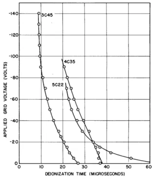
com-pare the three hydrogen thyratrons, 3C45, 4C35 and 5C22, since these tubes are of a similar design. The test data for three tubes of these types with an approximate gas pressure of 480 microns and obtained under identical
test conditions is shown in Figure 6. The effects of anode current and gas pressure in the 4C035 are illustrated by Figures 7 and 8.
The experimental data presented up to this point deal with tubes in which hydrogen is the active gas. Some indication of the effects of the nature of the enclosed gas upon deionization is obtained from tests on tubes
containing argon, hydrogen, mercury vapor and zenon as the active gas (with atomic weights of 40, 1, 200, and 130, respectively).
The FG67 is a mercury-vapor thyratron particularly designed for rapid deionization. The close spacing between the glass wall, and the anode and the upper grid structure increases the recombination of the ions at the walls and electrodes. The deionization time of the FG67 with the anode
cur-rent as a parameter is shown in Figure 9. Although this tube has the
-140 , a
-60
-20 I .____ c A X
I 19 I'l s "RI
Fig. 4 Influence of anode current upon deionization time. Sylvania 3C45: grid resistance, 20 K; repetition frequency, 250 cps; pulse duration, 1 sec; gas, hydrogen.
DEIONIZATION TIME (MICROSECONDS)
DEIONIZATION TIME (MICROSECONDS)
-5-O C, 0 S-0 (D 4 I--J0 0 _I a. a. --- --
---140 --120 - l -100 -I I -60 390F 270L 340 1 \470 1 \570p. -40 , l_ -20 0 2 4 6 8 10 12 14 16 18 20 22 24 26 DEIONIZATION TIME (MICROSECONDS)
Fig. 5 Influence of gas pressure upon
the deionization time. Sylvania 3C45: anode voltage, 900 volts; anode current, 10 amp; grid resistance, 20 K; repetition
frequency, 250 cps; gas, hydrogen.
-120 -100 2 3 4 -80 ANODE CURRENT --5 AMPERES 2--10 3--20 -60 ____0 I
~-~0 ~4-30
C-20\ L\
0 0~
8 16 24 32 40 DEIONIZATION TIME (MICROSECONDS)48 F I-0 w 0 4 C-a -j 0 a. t -140 345 -120 -100 4G35 -80 5022 -60 I -40 -20 0 0 10 20 30 40 DEIONIZATION TIME (MICROSECONDS)
Fig. 6 Deionization time of the hydrogen thyratrons. Anode voltage, 900 volts; anode current, 10 amp; grid resistance, 20 K; repetition frequency, 250 cps; pulse duration, 1 sec.
g
I-LI)
Fig. 7 The effect of anode current upon
the deionization time. Sylvania 4C35: grid resistance, 50 K; repetition frequency,
1000 cps; pulse duration, 0.5 sec; gas
pressure, 480 microns; gas, hydrogen.
-120 -100 - I GAS PRESSURE I -- 260 MICRONS 2-- 430 3-- 650 -60 t* -4-- _ 700 -40 -20 \__ __3 0 8 16 24 32 4 DEIONIZATION TIME (MICROSECONDS)
Fig. 8 The effect of gas pressure upon
the deionization time. Sylvania 4C35:
anode voltage, 900 volts; anode current,
10 amp; grid resistance, 20 K; pulse duration, 1 sec; repetition frequency,
250 cps; gas, hydrogen.
-6-so F o w C--J 0 0. In R 3-0 w -J 0 0 0 0 a w -a. a. 50 60 --IP i > I-0 0 a U) 4i: -J 0.
DEIONIZATION TIME ( MICROSECONDS)
Fig. 9 The effect of anode current upon deionization time. FG67: Grid resistance, 20 K; oil-bath temperature, 65°C; vapor pressure, 0.035 mm; pulse duration, 0.5 psec.
v0 200 400 600 800 1000 DEIONIZATION TIME (MICROSECONDS)
Fig. 11 The effect of vapor pressure upon deionization time. 3C23: anode
voltage, 480 volts; anode current, 5 amp;
grid resistance, 5 K; pulse duration, 5 sec.
DEIONIZATION TIME (MICROSECONDS)
Fig. 10 The effect of vapor pressure upon deionization time. KU627: anode voltage, 200 volts; anode current, 2 amp; grid resistance, 20 K; pulse duration, 1 sec. o -j 0 (9 w U) or 0 a-a.
DEIONIZATION TIME (MICROSECONDS)
Fig. 12 The effect of grid resistance upon the deionization time. FG17: anode voltage, 220 volts; anode current, 2 amp; vapor pressure, 0.00278 mm; oil-bath temperature, 30'C; pulse duration, 5 sec.
-7-u) o I-; 0 w LU 9 0 0 -J 0o o4 I-0 w 0 FI--J 0 a 2 U) 0 w -J a a.
__ _III___
rmll_
__I _I_
I
shortest deionization time of the mercury thyratrons which were tested, it also is the most inconsistent of the group. This variation is probably due to its double-valued control characteristic. The increase in the time scale of the graphical results of the FG67 should be observed.
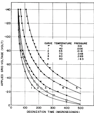
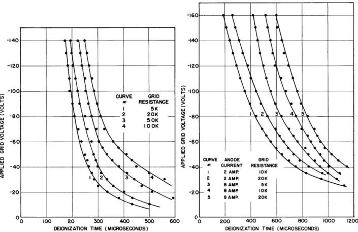
The KU627 showed very consistent results when similarly tested. The effects of vapor pressure upon the deionization time are shown in Figure 10. The recently developed 3C23 mercury thyratron compared favorably with the KU627. The effects of its vapor pressure are shown in Figure 11. The effects of grid circuit resistance upon the deionization time for the FG17 and FG57 are illustrated in Figures 12 and 13.
The xenon-filled EL CB thyratron is often used in conjunction with servo motors in various control systems. The deionization time of this tube, using anode current and grid resistance as parameters, is shown in Figure 14. Again, the increased time scale should be observed. The deionization time is much larger than that of the KU627.
-16 -140 - --120 I -I00 CURVE GRID * RESISTANCE 5K -80 2 20K 3 50K 4 lOOK -60 -40 -20 A 0 100 20 300 400 500 DEIONIZATION TIME (MICROSECONDS)
Fig, 13 The effect of grid resistance
upon the deionization time. FG57: anode voltage, 550 volts; anode current, 5 amp; vapor pressure, 0.0089 mm; oil-bath tem-perature, 45eC; pulse duration, 5 sec.
6C -I" -12 aW -I U) I- I C -J _J 0 a aW tI a-% -4 -2 )0 '0 200 400 600 800
DEIONIZATION TIME (MICROSECONDS)
Fig. 14 The effect of anode current and grid resistance on deionization time.
El CB: anode voltage, 440 volts; pulse duration, 5 psec; repetition frequency, 250 cps; gas, xenon.
-8-S U, I-_J 0 Wa .4 -0 a CD a a-4I I 1 k_ 5_CURVE ANODE GRID
G CURRENT RESISTANCE 1 2 AMR IOK 2 2 AMP. 20K 3 8 AMP. 5K o 4 8 AMP IOK 5 8 AMP. 20K I 1000 1200
IV. Conclusion
A considerable amount of quantitative data were obtained for various thyratrons which were operated under dynamic conditions similar to those encountered in practice. The concluding table lists a few of the character-istics of some of the thyratrons which were used in this investigation. In general, a small anode current, a low gas pressure, a large grid bias, a low-impedance grid circuit, a large plasma cross section, a short axial plasma length, and a small electrode separation favor a shorter deionization time.
The method of measurement of deionization time used in this investiga-tion is to be preferred to the conveninvestiga-tional capacitor-discharge circuit for
several reasons: (a) The anode voltage during the post-conduction period
is maintained at a constant value and can be reapplied instantly (within 0.3 microsecond) whenever desired. The time of voltage reapplication pro-vides an exact reference point (independent of reignition voltage) to which time measurements can be made. (b) The rate of rise of the reapplied anode
voltage is a constant value, irrespective of test conditions. (c) Since no
numerical computation is necessary, this circuit provides a rapid means of evaluating the deionization time.
-9-Tube Active Maximum Maximum, Maximum Average
Number Gas Peak Anode Peak Anode Instantaneous Tube Drop
Voltage Current Grid Current (volts)
(volts) (amp) (amp)
3C45 Hydrogen 3000 45 18 4C35 Hydrogen 8000 100 18 5C22 Hydrogen 16000 325 18 EL CB Xenon 450 8 8 EL C67 Xenon 750 77 9 EL C16J Xenon 1000 100 11 FG17 Mercury 5000 2.0 0.25 11.5 FG57 Mercury 1000 15.0 1.0 11.5 FG67 Mercury 1000 15.0 1.0 11.5 FG95 Mercury 1000 15.0 1.0 11.5 FG98 Inert Gas 500 2.0 0.25 11.5 3C23 Inert Gas 1250 6.0 0.05 11.5 Mercury KU627 Mercury 1250 2.5 0.25 15
Acknowledgment
The author wishes to acknowledge the many helpful suggestions and assistance which he received from Professor H. E. Edgerton and Mr. K. J. Germeshausen, and to express his gratitude to the Research Laboratory of Electronics which provided the necessary space and equipment for this
inves-tigation.
References
(1) A. W. Hull, General Electric Review 32; 213, 1929.
(2) M.I.T. Radiation Laboratory Report No. 692, "Colloquium on Pulse-Forming Networks".
(3) M.I.T. Radiation Laboratory Report M212, "Operating Instructions for the Model 5 Synchroscope.
