Designing and Editing
2.5-Dimensional Terrain in StarLogo TNG by
Daniel J. Wendel
S.B., C.S. M.I.T., 2005
Submitted to the Department of Electrical Engineering and Computer Science in Partial Fulfillment of the Requirements for the Degree of
Master of Engineering in Electrical Engineering and Computer Science at the Massachusetts Institute of Technology
August, 2006
0-'
C 2006 Massachusetts Institute of Technology All rights reserved
Author
Departmer ineering and Computer Science
August 21, 2006 Certified by Accepted by MASSACHUSETTS INSTITUTE OF TECHNOLOGY
OCT
3
2007
Eric Klopfer ation Program js- Supervisor :hur C. Smith -Iairman, Department Committee on Graduate ThesesDesigning and Editing
2.5-Dimensional Terrain in StarLogo TNG by
Daniel J. Wendel
S.B., C.S. M.I.T., 2005
Submitted to the Department of Electrical Engineering and Computer Science in Partial Fulfillment of the Requirements for the Degree of
Master of Engineering in Electrical Engineering and Computer Science at the Massachusetts Institute of Technology
August, 2006
Abstract
StarLogo TNG is "The Next Generation" in block-based decentralized programming for modeling and simulation software. Its aim is to make computer programming more appealing for students in middle school and high school. Part of the draw of StarLogo
TNG is its 3-D rendered world called Spaceland where "agents" live on a terrain made of
a grid of "patches". This thesis evaluates and outlines the redesign of Spaceland and its associated terrain editor based on user-task analysis, and discusses the design of new data structures to support the desired features.
Thesis supervisor: Eric Klopfer
Table of Contents
1. Introduction ... 7
1.1. W hat is StarLogo... 7
1.2. W hat is StarLogo used for?... 9
1.3. Drawbacks of StarLogo ... 10
1.3.1. Text-based programm ing ... 10
1.3.2. Simple 2D graphics... 11
1.4. Solution: StarLogo TNG ... 11
1.4.1. StarLogoBlocks... 11
1.4.2. Spaceland - a 3D world ... 13
2. Spaceland, version 0.9, Preview 1 ... 15
2.1. M oving from 2D to 3D ... 15
2.2. Design...16
2.2.1. Data storage... . 17
2 . . . R n e i g ... ... .. .6... 8
2.2.2. Rendering... 18
2.2.3. Stomp and yank... 18
3. Level Editor, Preview 1 ... 21
3.1. Prelim inary requirem ents... 21
3.1.1. W hatever an agent can do ... 21
3.1.2. Som e things an agent cannot do... 21
3.2. Design ... 21
3.2.1. Overview and layout... 21
3.2.2. Tools ... 23
3.2.3. M issing tools... 26
4. Evaluation of Preview 1... 28
4.1. Evaluation contexts... 28
4.1.1. After school at CCSC... 28
4.1.2. Physics class in M assachusetts ... 28
4.1.3. Teacher Education Program lab at M IT... 29
4.2. User observations and evaluations... 30
4 . . p ... 30 4.2.2. Observations ... 30 4.2.3. Evaluation ... 31 4.3. Terrain/level observations... 32 4.3.1. M azelike... 32 4.3.2. Scenic... 34 4.3.3. Picturelike ... 34 4.3.4. Agent-edited... 35
5. Revised Spaceland and editor requirem ents ... 38
5.1. Spaceland features ... 38
5.2. Block com m ands... 39
5.3. Editor tools... 40
5.3.1. Shaping tools... 40
5.3.2. Painting tools ... 40
5.3.3. Agent tools... 41
6. Spaceland and Editor, version 0.9, Preview 2 ... 44
6.1.1. Im proved Spaceland speed ... 44
6.1.2. Change color tool... 45
7. Spaceland, version 0.9, Preview 3 ... 46
7.1. N ew data structures... 46
7.1.1. Terrain structure... 46
7.1.2. Patch structure... 47
7.2. Textures... 47
7.2.1. Texture specification... 47
7.2.2. Com bining textures with colors ... 50
7.3. Rendering ... 50
7.3.1. Steady-state rendering... 50
7.3.2. Changing terrain... 52
7.4. Extensions to blocks ... 53
7.5. M issing Features ... 54
8. Editor, version 0.9, Preview 3+ ... 55
8.1. Im proved features ... 55
8.2. A dded features ... 56
9. Future w ork... 57
10. Conclusion ... 58
11. A cknow ledgem ents... 59
12. References... 60
Appendix A : Spaceland data structure files... 61
List of Figures:
Figure 1-1 The StarLogo Runtime environment. In this example, colored agents move
around on a world made of black and yellow patches... 8
Figure 1-2 Som e StarLogo Blocks... 12
Figure 1-3 A portion of code written with StarLogo Blocks... 13
Figure 2-1 Several shapes found in the StarLogo TNG shape library... 16
Figure 2-2 One red patch is divided into nine sub-patches. Two sub-patches are outlined in gray for clarity . ... 17
Figure 2-3 Vertex Multipliers for stomp and yank operations. ... 19
Figure 2-4 One red patch that has been yanked, surrounded by green patches... 19
Figure 3-1 Layout of the terrain editor for Preview 1... 22
Figure 3-2 A region of red patches that has been leveled, in the middle of a terrain full of green h ills... 2 3 Figure 3-3 A region of red patches that has been raised, in the middle of a terrain full of g reen h ills... 2 4 Figure 3-4 A crater drawn in the middle of a mound, forming a ring-shaped ridge... 25
Figure 3-5 The color palette that pops up when using the "paint" tool... 25
Figure 3-6 A terrain that has been painted with several different colors... 26
Figure 7-1 A sample of what a patch top source image might look like. The yellow rectangle indicates a possible portion of the image that would be specified by a patch's texture coordinates... 49
Figure 7-2 An example of a possible patch side source image... 49
Figure 7-3 A tilted red patch in the middle of green terrain ... 51
Figure 7-4 A green patch with brown sides raised two units above the surrounding
1. Introduction
StarLogo TNG (The Next Generation) is a 3D graphical programming
environment designed to help increase computer literacy, especially in students in middle school and high school. Its goal is to use novel tools and cool display capability to get students to write programs, expanding their powers of expression on the computer. In particular, StarLogo TNG is designed to be a flexible tool to let users with little or no prior programming experience create powerful, graphically attractive games without the need for text-based coding [3].
At the heart of this approach are StarLogoBlocks and Spaceland. StarLogoBlocks are small graphical representations of the various control and data structures in a
program, and Spaceland is the 3D projection of a customizable surface on which the game characters live. While the StarLogoBlocks are robust and nearly completely designed, the capabilities of Spaceland are not. Spaceland has now gone through two redesigns, and the editing tools needed to work with it are only beginning to take form.
This thesis project consists of the design and implementation of an editor for Spaceland. The project starts with a simple editor designed to meet the barest minimum requirements, evaluates it in light of actual usage, and concludes with the second
iteration, a design that better meets users' real needs.
1.1. What is StarLogo?
In order to better understand the workings of StarLogo TNG, it is useful to start with its predecessor, StarLogo version 2, hereafter referred to simply as StarLogo. StarLogo was developed as a tool for decentralized thinking and modeling. With a few lines of code, developers can model bird flocking behaviors, termite mound building, simple ecological systems, or any number of decentralized systems [6]. However, StarLogo's text-based language can be difficult for younger students to grasp, and its 2-dimensional graphics are no longer state of the art. This section discusses some of the benefits of StarLogo, as well as some areas that can be improved to let StarLogo reach a more diverse, less computer-savvy audience.
Two concepts form the core of StarLogo -patches and agents. The world on which the agents live and interact is made of a 2-dimensional grid of patches. Each patch has certain built-in properties, like color and user-defined properties, called patches-own
variables, that might include "vegetation cover" for an ecosystem model or "mound
height" for a termite model. A palette on the left-hand side of the StarLogo window features brush and shape tools for painting on the grid of patches. The patches'
properties can also be modified programmatically by agents on or around the patches or
by the "Observer," an all-knowing entity with access to global properties of the model.
In StarLogo, patches can even run a limited set of commands to modify themselves according to global properties such as the number of agents alive or the number of red patches. Patches are rendered as colored squares in the StarLogo runtime environment, as shown on the right-hand side of Figure 1-1.
:aa I-,nt ize winOOWS HIP
I
IU
-x:. YU
Figure 1-1 The StarLogo Runtime environment. In this example, colored agents move around on a world made of black and yellow patches.
Agents are the entities that can move around and interact programmatically with the patches and each other. Each agent is an instance of an object running "agent code." The agents are divided into species, which can run different code based on a simple if statement. The agent code specifies the movement and behavior of agents on a
decentralized, individual level, and each agent runs the code in its own virtual machine. In other words, each agent knows how it should move and behave based on the agent code for its species, but no central entity controls the group behavior of the agents. Any group behaviors that do emerge come from the interaction between individuals. Agents can have images associated with them, or can be invisible and simply paint patches as a record of their existence. Figure 1-1 shows the StarLogo runtime environment, with agents scattered around a world of yellow and black patches.
1.2. What is StarLogo used for?
StarLogo is a tool for decentralized thinking, aiding in the understanding of complex dynamic systems. Through interaction with StarLogo models (i.e. simulation projects), students can gain a better understanding of concepts such as:
" Predator/prey population dynamics
* Forest fire spread and containment strategies
" Bird flocking patterns " Termite nest building
As well as many more [6]. By interacting with models, rather than simply viewing static information, students can gain first-hand knowledge about the concept being modeled. For more information on StarLogo as an educational tool, see the Adventures in Modeling book by V. Colella, E. Klopfer, and M. Resnick, available from
Teachers College Press, and New paths on a StarLogo Adventure by the same authors
1.3. Drawbacks of StarLogo
Despite its usefulness for many applications, StarLogo also has several drawbacks that prompted the creation of "'The Next Generation." These drawbacks fall into two main categories: difficulty of programming and lack of graphical appeal.
1.3.1. Text-based programming
The difficulty in programming StarLogo models stems primarily from its dependence on its text-based programming language. Although the language is not difficult compared to other text-based languages such as BASIC or PASCAL, it still presents a high entry barrier for users with little or no programming experience, such as most junior high and high school students have.
The first difficulty is syntax. New users must repeatedly look up the proper syntax for commands in order to use them correctly; the commands themselves give no indication of the syntax with which they should be used. Even for users with prior experience with other programming languages, syntax is always a bit of a guessing game without the documentation. For example, the formatting of brackets and parentheses in a
StarLogo if-else statement, although easy to memorize, is unlike mainstream languages such as C, BASIC, and Java.
A related problem is that compile errors stemming from incorrect syntax are not
apparent until the users compile the code. By that time they have often shifted their focus to another aspect of the model and must spend time re-familiarizing themselves with the
problematic portion of code.
The final difficulty with the text-based language in StarLogo is its separation from the runtime environment. In order to change the code for a model, i.e. a StarLogo
project, users must switch to an editing window, make changes, and then switch back to the runtime interface to test. This also applies when users want to test a command to see what it does - they must switch windows, type the command, save and compile, and return to the runtime interface to run.
1.3.2. Simple 2D graphics
StarLogo's use of 2D graphics rendering for its patches and agents, although sufficient for many models and simulations, may be a drawback for many new users who are used to the advanced 3D graphics of modern computer games. Since even games for young children now use 3D characters and worlds, StarLogo's graphics may not have the appeal or "coolness factor" needed to draw students whose goals are to make games or simply to have fun [5].
Although the above drawbacks do not diminish StarLogo's usefulness for its original purposes, they deserve consideration for a more important reason: the Computing Research Association (CRA) reported in May 2005 that interest in computer science as an undergraduate major in the US dropped 60% between 2000 and 2004. Even more distressing is that only 0.5% of incoming female college freshmen expressed an interest in computer science as a major, an all time low since the early 1970s [9]. Additionally, Gee [2] states that children, although fluent in "reading" video games, are largely inept in the other half of computer literacy, "writing" [5]. There is clearly a need to make
programming more accessible to students across the board, and to provide an example of programming as an exciting, interesting activity.
1.4. Solution: StarLogo TNG
Enter StarLogo TNG, "The Next Generation" of StarLogo programming. StarLogo TNG's aims are similar to those of StarLogo: to provide a powerful platform for modeling and learning about decentralized systems. However, StarLogo TNG also addresses the problems and shortcomings of StarLogo, providing a programming
environment that is both easy andfun for students to use. StarLogo TNG addresses these goals by introducing two significant changes to StarLogo: blocks-based programming and a 3D rendered world [5].
1.4.1. StarLogoBlocks
The StarLogoBlocks concept was developed as a graphical alternative to text-based programming. As in LogoBlocks [1], the graphical language after which StarLogo TNG's language is patterned, StarLogoBlocks commands take the form not of textual words, but of graphical "blocks" as shown in Figure 1-2. These blocks can be snapped
together like pieces of a jigsaw puzzle to form complete programs. Figure 1-3 shows a portion of code written in StarLogo TNG's StarLogoBlocks language.
Figure 1-2 Some StarLogo Blocks.
In blocks-based languages, syntax can be given by visual cues, i.e. the shapes of the blocks themselves. It is therefore immediately obvious if two commands do not fit together syntactically, as their shapes are not compatible and hence do not snap together. In the same way, commands that require arguments are given "sockets" that must be filled. Notice, for example, the block labeled "set energy" in Figure 1-3. It has an angular socket on the right side, indicating that it requires a number argument, and conversely, the number block is shaped such that it fits into the socket.
sHit"
Tm
t m
Figure 1-3 A portion of code written with StarLogo Blocks.
This shape-based syntax indication not only provides clues for what arguments are required by commands, but also provides error prevention and feedback [3]. Unlike StarLogo, where it is necessary to compile code in order to find out where the errors are, in StarLogo TNG one can see errors immediately; it is instantly obvious if two blocks placed next to each other do not snap together, and it is also obvious when a block's socket is empty.
1.4.2. Spaceland - a 3D world
The second large improvement in StarLogo TNG is the addition of Spaceland, a
3D rendered world in which the agents live. Spaceland takes StarLogo's concept of a
grid of 2D patches and adds another dimension - height. The patches themselves are actually 2.5D. This means that for any (x,y) coordinate in the grid, there is exactly one height. In other words, the patches are rendered as a grid that cannot overlap itself. However, agents in StarLogo TNG can exist anywhere in the 3D space above and below this 2.5D grid of patches. It is our hope that the addition of this 3D graphical capability will make StarLogo TNG more enticing to today's youth [5].
Of course, the introduction of 3D into StarLogo TNG required more than just a
change of rendering. Additional height-changing commands needed to be added to the StarLogo language to allow users to control the 3D properties of patches, as well as the
3D properties and movement of agents. Additionally, the old painting tools used in
StarLogo are no longer sufficient; painting only covers a small subset of the new needs for editing 2.5D terrain. This thesis project focuses on designing a framework for and editing the new 2.5D terrain.
In this paper I introduce the first version of Spaceland along with a simple terrain editor I developed for it. I then evaluate Spaceland and its editor in light of feedback gained from real world use cases. I analyze some of the tasks these users tried to accomplish in order to develop a specification of requirements for the next iteration of Spaceland and its editor's design. Finally, I propose, implement, and evaluate a design for the next version of Spaceland and its editor.
2. Spaceland, version 0.9, Preview
1
The first version of StarLogo TNG to be released to the public was version 0.9, Preview 1. Preview 1 contains rough versions of most of the target features of StarLogo
TNG, including a user interface for block-based programming and a 3D rendered window
showing Spaceland, the virtual world in which StarLogo TNG agents live.
2.1. Moving from 2D to 3D
In order to move into 3D, StarLogo TNG had to add several new features to the original StarLogo design. The first step in moving to a 3D world was extending the StarLogo commands and agents to take three dimensions into account. To this end, agents were given several new properties relating to their 3D location and appearance, and several commands were added to the StarLogo language to change the properties. Additionally, a few commands were added for changing the heights of the patches in the terrain.
Each agent has a property specifying its shape. Although this concept is not new in StarLogo TNG, the shapes themselves are. Agents rendered in Spaceland must have
3D shapes, so an entirely new palette of shapes was developed. For Preview 1, the
available shapes include basic shapes such as spheres, cones, and cubes, as well as letters, numbers, and more complicated character shapes. The more complicated shapes include
.OBJ models of several animals, as well as .MD3 shapes imported from some of the
countless Quake 3 websites. Spaceland's ability to draw shapes from both .OBJ and .MD3 file formats also allows users to import 3D shapes of their own into StarLogo TNG's shape library. Figure 2-1 shows agents of several different shapes from the
Figure 2-1 Several shapes found in the StarLogo TNG shape library.
The most obvious agent property that was added is altitude, which specifies an agent's height above the terrain. The set-altitude block was added to control this property, allowing users to create programs in which agents appear to be floating above the terrain or even wading through it. A corresponding reporter block was also made, which reports the agent's current altitude.
Similarly, the most obvious patch property that was added is height, which
specifies a patch's height relative to the middle of Spaceland, or what would otherwise be known as sea level. This height can be changed and read by four commands that were
added to StarLogo TNG's language: stomp, yank, patch-height, and ph-ahead. Stomp
and yank are the commands to change a patch's height. When agent executes a stomp command, the patch under that agent is lowered by the given amount. Conversely, when an agent executes a yank command the patch under the agent is raised. The
patch-height command reports the patch-height of the patch the agent is standing on. The ph-ahead
command reports the height of the patch one unit in front of the agent.
2.2. Design
The patches in Preview 1 of Spaceland are arranged in an evenly spaced square grid 101 patches on a side, allowing for patch coordinates from -50 to 50. Patches share
vertices at the corners and sides, making for a smoothly connected terrain. Additionally, each patch is divided into nine sub-patches, arranged in an evenly spaced 3 x 3 grid. The height is stored at each corner in the grid, giving the editor sub-patch height control. Each of the nine squares is rendered as two triangles, which is standard practice for OpenGL rendering. Figure 2-2 shows one red patch surrounded by green patches on the side of a mound. Notice the nine sub-patches each rendered as two triangles. Emphasis is added on two sub-patches to make the distinction clearer.
-~ - jv -=I.
1~ AJL21D~
Figure 2-2 One red patch is divided into nine sub-patches. Two sub-patches are outlined in gray for clarity.
2.2.1. Data storage
The data for this terrain of patches is stored in two Java ByteBuffers that can be read both by the Java front-end and the C virtual machine that make up StarLogo TNG. The first ByteBuffer contains data with which the agents can interact. This includes the patch color, the patch height (as an average of its nine sub patch corners), and a pointer to the patch heap, a location in memory where any user-defined variables for that patch are
The second ByteBuffer stores data related to how the patches are rendered, including the nine sub-patch heights. Although this data is modified by the stomp and yank commands, the data is only ever read by the terrain-rendering code.
2.2.2. Rendering
Spaceland, including agents and the terrain, is rendered using JOGL, a Java binding to OpenGL. The terrain is rendered as a series of 303 triangle strips (because there are 303 sub-patches on a side), each containing 606 triangles. Each of these triangle strips can be converted to an OpenGL display list for much more efficient rendering. However, a display list must be recomputed whenever the data for one of its triangles changes. This means that the execution of common commands, such as stamp, to change the color of a patch, or stomp, to change the height of a patch, results in substantial recalculation. Sections 4.2.3 and 6.1.1 address this issue in more detail.
2.2.3. Stomp and yank
Due to the connected nature of Preview l's Spaceland terrain, it is impossible to change the height of a whole patch without changing its neighboring patches. Given the
3 x 3 grid of sub-patches, however, is possible to change the height of part of the patch
more than other parts. Preview l's design of stomp and yank takes advantage of this fact. Sections 4.3.1 and 4.3.2 discuss how this connected version of stomp and yank, although good for creating smooth mountainous features, is less than ideal for creating vertical walls.
The design of stomp and yank in Preview 1 is based on the observation that if all of the patches in a certain region are yanked by the same amount, the region should still appear to be flat and connected, but higher than the surrounding terrain. In order to maintain this behavior, a grid of multipliers was devised that indicates what fraction of the total height a given vertex should move. For example, the four corner vertices of the patch are assigned a .25 multiplier so that if the four patches sharing a corner are all yanked, the vertex between them will be at the same height as their centers. Figure 2-3
shows the multipliers for each vertex of a patch. Figure 2-4 shows a red patch that has been yanked by one unit, surrounded by green patches. Sidebar 1 shows how using this grid, when yanking four patches sharing a corner, yields a plateau.
YANK VERTEX MLTIPLIERS
0.5
*j.75
11
Figure 2-3 Vertex Multipliers for stomp and yank operations.
Figure 2-4 One red patch that has been yanked, surrounded by green patches.
Sidebar 1
This progression of images shows the heights of the vertices of four adjacent patches as the patches are yanked one-by-one. Notice that at each iteration, the patches that have been yanked share a middle region (colored blue) with height equal to 1.
.1 N / ' / ' \ / V Iq -I \ \ i F 11 -I ~ \ / IL ,kI -, \ -' , 11 1 IRV ~' / /1k /U Ik 'd k V IF Ik Ik IRV 'qV IRW /T.% /bL /bL Ak 0 .25 .5 .75 1
IRV IRV IRV
Ah Ilk /1% 'Ift Ak /1k /Ik IRV Ah @ IRV IRV Nr Mv W 11 W 11 W k F 14 J J
3. Level Editor, Preview
1
The design of Spaceland also gave rise to the need for level editor to allow users to shape and paint the terrain. To this end, I developed a simple editor with a bare minimum of tools that we could distribute as a part of this first Preview release of StarLogo TNG.
3.1. Preliminary requirements
The first step in designing this simple editor was to develop some basic
requirements. The first set of requirements included actions that could be done by agents running block code, such as setting the height or the color of patch. The second set of requirements was for macroscopic tools that an individual agent could not do.
3.1.1. Whatever an agent can do
The two properties that an agent can control about a patch are its height and its color. However, agents can only affect one patch at a time. Therefore it seemed useful to require tools that could:
1. Control the height of a region of patches, and 2. Control the color of a region of patches.
3.1.2. Some things an agent cannot do
Three other tools were required for editing the terrain in ways agents could not. These high-level requirements were for tools that could:
1. Draw smooth mounds,
2. Place agents around the terrain, and
3. Change the dimensions of the terrain's grid of patches.
3.2. Design
3.2.1. Overview and layout
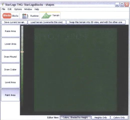
Figure 3-1 shows the general layout of the terrain editor for Preview 1. The terrain is represented by a grid of squares in the middle of the window. Tools for editing the terrain are along the left-hand side of the window, next to a bar used for choosing heights. Along the top left of the window are buttons for saving and loading terrains, and the bottom right has buttons for changing the view.
StarLogo TNG: StarLogoBlocks -shapes File Edit Options Window Help
Blocks Runtime Terrain
Save current terrain Load terrain (overwrite this one) Swap this terran into 3D view, and edit the other one Rase Area
Lower Area
Draw Mourd
Draw Crater
Level Area
Heights Ory [ Colors Only
Figure 3-1 Layout of the terrain editor for Preview 1.
The editor for Preview 1 inherited an unfortunate "edit then swap" methodology from its predecessors. In this design, Spaceland displays one terrain, while the editor controls another. In order to make Spaceland show the terrain he/she just edited, the user must click a button to swap the terrains, bringing the terrain from Spaceland into the editor, and putting his/her terrain into Spaceland. The large button on the upper right hand side of the editor window controls the swapping of terrains.
The editor has three selectable viewing modes for the terrain. The default mode,
colored height, shows the colors of the patches, but shades them according to their
heights, with higher patches being shaded more brightly. The height-only mode ignores the colors of the patches, shading them instead using a height-dependent gradient. This gradient ranges from black for -50 to white for positive 50, passing through shades of green in the middle for added contrast. The color-only mode ignores the height information of the patches, displaying only their actual, unshaded colors.
3.2.2. Tools
The terrain editor for Preview 1 has four tools that, along with the height slider, provide the functionality of the terrain editor. They are listed below along with a description of how they work.
Level: The level tool brings all of vertices of all of the selected patches to the same
height, effectively leveling the patches. The position of the height slider determines what height the patches will be brought to. Figure 3-2 shows a region of red patches that has been leveled, in the middle of a hilly terrain full of green patches. Notice that of the two visible "walls" of this plateau, one is green, while the other is red. This is due to the connected nature of the terrain; the south and east edges of any region will slant if necessary to connect to the surrounding terrain.
Figure 3-2 A region of red patches that has been leveled, in the middle of a terrain full of green hills. Raise/lower: The raise/lower tools interpret the height slider differently than the level
tool. Rather than reading it as an absolute value, the raise and lower tools interpret it as an offset. The raise tool simply adds the height on the height slider to the height of every vertex of the selected region of patches. Similarly, the lower tool subtracts the height of
the height slider. Figure 3-3 shows a region of red patches that has been raised in the middle of a hilly terrain of green patches.
Figure 3-3 A region of red patches that has been raised, in the middle of a terrain full of green hills. Mound/crater: The mound (and similarly, crater) tool can be used to make curved
terrain features. Like the raise and lower tools, the mound and crater tools interpret the height slider's value as an offset rather than as an absolute height. However, unlike the raise and lower tools, the mound and crater tools do not apply this offset uniformly to the
selected patches. Instead, they change the center patches by that amount and taper off toward the edges of the selected region, thereby creating a mound or crater. An inverted cosine curve is used to determine the tapered heights, since it yields a rounded shape which transitions smoothly from level terrain to the slope of the mound. Figure 3-4 shows a crater drawn in the middle of a mound, forming a ring-shaped ridge.
- I
Figure 3-4 A crater drawn in the middle of a mound, forming a ring-shaped ridge.
Paint: The paint tool sets the color property of the patches in the selected region. When
the user clicks on the paint tool button, a small dialog box, shown in Figure 3-5, pops up asking the user to choose a color. Subsequently selected patches will be set to the selected color. Figure 3-6 shows a terrain that has been painted with several different colors.
OK
- Fcancel
11
*
Figure 3-6 A terrain that has been painted with several different colors.
3.2.3. Missing tools
Two of the requirements for the terrain editor are conspicuously missing from the design of the editor for Preview 1: the ability to place agents, and the ability to resize the terrain.
The ability to place agents on the terrain was temporarily implemented for this editor. However, the editor had to store agent placement data internally, since the design of the terrain data structure in Spaceland had no place for storing data. Additionally, agents and agent properties are not stored with project files in StarLogo TNG. Therefore, although users could place agents, they could not recover or save this placement. For this reason, the agent placement tool was disabled until the rest of the StarLogo TNG system could support it.
Terrain resizing faced a similar lack of support in the backend. The size of the terrain, rather than being stored in a data structure, was hard-coded into several
interdependent modules of the StarLogo TNG virtual machine and Spaceland. Even if the terrain editor changed its representation of the size of the terrain, Spaceland would
still render the terrain as a grid of 101 x 101 patches. Terrain resizing was also disabled until sufficient backend support for it existed.
4. Evaluation of Preview
1
4.1.
Evaluation contexts
The following evaluation of Preview 1 is based on observations of users using the system in three contexts. The first was an after school program at a nearby junior high school. The second was a ninth grade conceptual physics class in Massachusetts. The third was the Teacher Education Program lab at MIT where StarLogo TNG is being developed.
4.1.1. After school at CCSC
The first context in which we observed users interacting with StarLogo TNG was at an after school program at the Community Charter School of Cambridge. At CCSC our users were seventh, eighth, and ninth grade students with a wide range of previous computer experience. They all chose the StarLogo TNG after school program over other options, presumably lured by the idea that they could make their own computer games. The after school program lasted approximately 9 weeks, with most students attending between two and eight sessions.
The curriculum used for the after school program was developed by Kevin Wang, in conjunction with the StarLogo TNG developers. An improved and updated version is available on the StarLogo TNG web site as a tutorial for new users. The idea of teaching computer programming concepts through the use of StarLogo TNG with this curriculum was presented at the International Conference for the Learning Science during the summer of 2006 [4].
The computers used for this after school program were Dell laptops with Intel Celeron processors and 256 MB of RAM. They had an integrated Intel graphics chipset with shared graphics memory.
4.1.2. Physics class in Massachusetts
The second context in which we collected observations about StarLogo TNG was in a ninth grade conceptual physics class at the Governor's Academy in Newbury,
Massachusetts. The students were all ninth graders with a general distaste for math and a wide range of previous computer experience.
The observations from this user group were sent to us by their teacher, Hal Scheintaub, who also developed the curriculum that was used in this class. He will be presenting a poster at the International Research Group on Physics Teaching (GIREP) conference in Amsterdam about his success in using StarLogo TNG programming to teach physics concepts. As one of our most active users, Dr. Scheintaub also sent us numerous observations about his own interactions with StarLogo TNG.
The computers that these students used were older Dell OptiPlex desktops with
1.7 GHz Intel Pentium 4 processors and 256 MB of RAM. The computers initially had 32MB ATI Rage 128 Ultra graphics cards, but these proved to be much too slow to display Spaceland at an acceptable frame rate. We purchased and installed NVIDIA
GeForce FX 5200 graphics cards instead, which enabled the computers to display models where the agents were simple shapes such as spheres and cubes.
4.1.3. Teacher Education Program lab at MIT
The group of StarLogo TNG users at MIT consisted of a mix of researchers, developers, and college students. The researchers and developers were well aware of StarLogo TNG's capabilities, as each of them had a part in its design. The college students in this group were taking education classes at MIT and had a range of computer backgrounds, although most had strong mathematical skills and several had programmed before. Most of the observations from this group were made by the users themselves and emailed to the StarLogo TNG developers email list.
Most of the users in this group were concerned with making models that demonstrated educational concepts such as osmosis, erosion, planetary orbit,
predator/prey population dynamics, decision-making, or emergent properties. However, some were also interested in making sample games such as simple role-playing games or first-person shooters.
The computers that these users used ranged from old laptops with integrated graphics to then state-of-the-art AMD Athlon 64 based systems with NVIDIA 6600 GT graphics cards. Many users in this group also worked on Macintosh computers, and one used Linux on his laptop.
Both the CCSC after school program and the ninth grade conceptual physics class focused mainly on teaching programming concepts through the use of StarLogoBlocks. Although students in both groups made heavy use of the terrain editor, their training consisted of a brief demo after which they were allowed to experiment. The users in the Teacher Education Program (TEP) lab similarly focused predominantly on the blocks, although they did interact often with Spaceland and the terrain, as many of their models had agents interacting with and changing the terrain.
Since the focus of this paper is on Spaceland and the terrain editor, I will focus on observations related to those aspects of StarLogo TNG, though they form only a small subset of the observations we were able to gather from the users. For further discussion regarding other aspects of StarLogo TNG, see the detailed description of StarLogo TNG
by lead designers Eric Klopfer and Andrew Begel [3] or Corey McCaffrey's thesis on
improving block programming efficiency [7]. Additionally, look for future work by Ricarose Roque on debugging StarLogo TNG models.
4.2. User observations and evaluations
The following sections summarize some of the common observations from the three user groups, and evaluate the design of Preview 1 based on those observations.
4.2.1. General Spaceland and editor
The following two sections discuss observations and related evaluations of General Spaceland and editor functionality.
4.2.2. Observations
Although users rarely paused to make observations about parts of StarLogo TNG that were working well, most of the students seemed to enjoy using the terrain editor to change the appearance of the patches in Spaceland. Once they were shown how to swap terrains between Spaceland and the editor, users tended not to have any trouble with it. In fact, the typical usage pattern was to make a change with a tool, swap terrains to view the change, and then swap back to continue editing.
The users did have a few general complaints. Of these, the most frequent was that StarLogo TNG was simply too slow. On the computers that the middle/high school
students were using, models in which agents walk around Spaceland interacting with each other could run at between 10 and 20 frames per second. However, frame rates for models in which agents were changing the colors or heights of patches dropped to between one and five frames per second. Even on the fastest computers tested, frame rates for such models hovered below 30 frames per second.
The other two frequently mentioned complaints were that: 1) there was no undo function and 2) there was no way to "reset" a terrain to the way it was before the agents
in a model modified it. The lack of an undo function had the potential to be very
frustrating because it often resulted in lost work due to mistaken edits. The lack of a reset mechanism also resulted in lost work, but in this case, it was due to the running of a model, a purposeful action essential to the StarLogo TNG design.
4.2.3. Evaluation
Based on the observation that users would frequently swap their terrain into Spaceland to see what it looked like, it is apparent that the swapping mechanism is an unnecessary annoyance to the user. Rather than making users swap terrains, it would make more sense simply to view the terrain in both Spaceland and the editor
concurrently, updating Spaceland's view after every edit.
The obvious solution to the problem of speed is to improve the efficiency of Spaceland to make it faster on more platforms. This merited a careful look at the
rendering code for Spaceland. Radu Berinde, one of our developers, found several places in which the rendering code created unnecessary new variables or did unnecessary
recalculations. However, at the heart of the biggest slowdown was the decision to render the terrain as many triangle strips and to internally mark modified strips as needing
re-rendering. This design meant that if even one patch in a strip was changed, the entire strip would need to be re-rendered. It did not take very many agents running terrain-modifying code before the entire terrain would need to be re-computed and re-rendered every frame.
The lack of reset functionality was also due to a design shortcoming. Because both edits and agent actions took place on the same terrain data structure, agents running a program with terrain modifying commands would destroy prior editing work that the
user had done on that terrain. Despite there being two terrains in the system, there was no way to copy from one to the other. The only way to reset a terrain after agents had modified it was to save the terrain beforehand and then reload it.
What many users desired in an undo tool was actually the ability to erase terrain features and reset the patches to their initial flat, green state. However, many other users desired a true multi-command undo history. Still, due to direct manipulation style of the editor, users were able to rebuild lost features, indicating that the lack of undo at least did not hinder their ability to create terrains.
4.3. Terrain/level observations
In observing the levels made by the users, it became apparent that most of the levels could be classified into three categories: mazelike, scenic, and picturelike. A fourth type of level, in which agents shaped the terrain somehow, was less common in the student models but more common in the educational simulations. Of course, many levels displayed characteristics of multiple categories of levels. The categorization here is for the sake of analyzing tasks specific to those characteristics. The following four sections describe the characteristics of these levels, as well as problems users encountered with them, in more detail.
4.3.1. Mazelike
The levels that I categorize as mazelike were characterized not by their
appearances, although they often looked like mazes, but by the way agents in the models interacted with them. In these models, agents would read the terrain properties, taking different actions if they encountered patches of various heights or colors, for example. The most common usage of patch property differences was to provide boundaries for agents in the model, in the form of walls or colored lines.
Observations: The most noticeable problem that users had with this type of level was
that agents would often walk partway up walls that were supposed to form a boundary for them. This problem would appear regardless of whether the agents were checking the height or color of the wall patch as the condition for stopping. A problem whose cause
was much more difficult to trace was that sometimes agents would fail to recognize the boundary colors at all.
Many users also expressed dissatisfaction with the coloring of the walls they would make. In some cases, this was due to the fact that the south and east sides of a wall would be painted the color of the top of the wall, while the north and west sides
would be painted the color of the surrounding terrain. However, many users also said they wanted to be able to paint the walls independently of the colors of the tops of the walls or the surrounding terrain.
Evaluation
The problem of agents walking on the sides of walls was related to the connected nature of the terrain. In order for one patch to be higher than its neighbor, either a part of its or its neighbor had to be sloped to connect the two. In Preview 1, the southern and eastern sub-patches would slope as necessary to connect to the surrounding terrain. This meant that it was possible for an agent to be standing on a patch whose reported height was zero, but, by standing on the sloped portion, to appear to be halfway up the side of a wall. For the same reason, agents could be found standing halfway up a green colored wall when the color of the top of the wall, for example red, was a boundary color for that agent.
The connected nature of the terrain was also the reason that users could not paint sides of walls independently of the tops. Since the side of wall was actually the southern or eastern extension of a patch, it was impossible for the side of the wall to be colored
differently than the patch itself without redesigning the data structure that held patch properties.
The scenario in which agents would simply not respond to a color was traced back to the way colors are stored in StarLogo TNG. Agents checking for color are checking for numeric matches, since colors are stored as numbers in the virtual machine.
However, users editing a terrain would choose a color from the palette presented by the paint tool. The problem occurred when users thought they were choosing green, for example, but were actually choosing a color that would be internally represented as green+1 or green-1.
4.3.2. Scenic
The terrains that I categorize as scenic often had rolling hills, plateaus, walls, and several colors. Their purpose was simply to act as a backdrop for a model; if agents interacted with the terrain I classified it as mazelike or agent-edited. Many of these models used hills or small walls to limit visibility, or large, gentle mounds which seemed more realistic than the purely flat terrain.
Observations
Unfortunately, users found that it was difficult or impossible to make terrains look as realistic as they would like. Neither the editor tools nor the agents were capable of adjusting the slope of an individual patch, so structures such as ramps were impossible to build. Additionally, some users mentioned that a tool that could import heightmap data from other sources would be extremely useful.
Spaceland is rendered inside a "skybox," a large six-sided shape with images rendered on the inside. Spaceland's skybox shows images of a mountain range beneath a blue, sunny sky. Many users making scenic terrains expressed a desire to be able to choose a different skybox from a library, or least to be able to turn it off. Similarly, some users, especially in the TEP lab, said that the ability to make the terrain itself invisible would be useful for some of their models.
Evaluation
Unlike the problems encountered by the creators of mazelike levels, the problems creating scenic levels were due to a lack of editing tools and agent program commands rather than core design shortcomings. Additional tools for shaping the terrain can be added to the editor, and commands for changing the skybox and showing or hiding the patches can be added to the StarLogo TNG language.
4.3.3. Picturelike
The defining characteristic of a picturelike terrain is its use of color for artistic or aesthetic purposes. The patches in these terrains might be colored to form shapes, a smiley face, a map, or even a low resolution color photo or drawing.
Observations
Users who wanted to draw pictures on the terrain immediately complained that there was only one painting tool, and that it could only draw rectangles. I therefore
immediately changed the editor slightly so that the selected paint color would be applied to all tools. This way, by selecting a zero height and using the mound tool, users could
draw circles and ellipses. While this change was a vast improvement, users still had to draw many shapes, such as diagonal lines, one patch at a time.
Some users wanted turn the entire terrain into a map or photo. For these users, neither of the rectangular nor elliptical drawing tools were of much help; they could both be used to fill in large areas of color, but detail work had to be done one patch at a time.
Evaluation
Although the rectangle and ellipse tools were useful, they were simply inadequate for many of the tasks users desired to accomplish. A common task, drawing a line, had no associated tool. Users did not even attempt more complicated shapes such as stars or curves, presumably because the tools did not exist.
Drawing a map or photo on the terrain would also be greatly assisted by the proper tools. For example, users said that the ability to import a picture from an external file would be very useful. An editor tool could be developed to assign patch colors based on an image, assigning patch colors according to the pixel colors of the image.
Fundamentally, though, the one color per patch limitation would still prevent users from drawing detailed pictures on the terrain. For the users, it would be much more useful for each patch to be rendered with a texture, i.e. a small image, rather than simply a color. In the case of importing a picture, it would be ideal to chop the picture into 101 x
101 sub pictures and have each patch display its own sub picture. This ability would also
be ideal for maps or cases where users wanted the terrain to look like rock, dirt, or grass.
4.3.4. Agent-edited
Agent-edited terrains occur in models in which the initial features are less
important to the user than the features that arise as the result of agents running modifying commands on the patches. Although there are many such models, I will focus on two particularly informative ones, the erosion model and the termite model.
In the erosion model, users could swap a hilly terrain into Spaceland and watch as eroding agents carved away at it. The eroding agents were born randomly near the center of terrain and would flow downhill from there, stomping the terrain as they went in an attempt to mimic erosion.
In the termite model, the setup code randomly scattered raised yellow patches ("woodchips") throughout the terrain. The termite agents would then wander randomly around the terrain. If they bumped into a raised yellow patch, they would "pick up the wood chip" by stomping the patch and setting its color to green. They would then wonder until they were next to or on top of another yellow patch, in which case they would "drop the wood chip" by yanking the yellow patch. As this process ran, the wood chips would begin to form "piles" (raised yellow mounds) rather than being randomly scattered.
Observations
Two observations arose from the erosion model. First was the observation of how vital resetting the terrain is for some models. It became frustrating having to redraw the terrain every time, despite the fact that no particular terrain shape was required. The second observation was that the "eroded" terrain did not quite look eroded because the slopes of the patches were unchanged, with the exception of the south and east
connecting sub-patches.
The most interesting observation that arose from the termite model was that, given enough time, the wood chips would form one pile in a corner of the terrain. This was confusing at first, but we soon determined that it was due to the fact that corner wood chips, being inaccessible from three quadrants, were the least likely to be picked up because they only needed three surrounding yellow patches in order to be completely protected from being picked up.
Evaluation
The erosion model confirmed the need to add the ability to reset terrains to the design of Spaceland, despite there being no existing support for it as discussed in the general evaluation of Spaceland.
The observation about the appearance of the eroded terrain had a less obvious
solution. Although stomp and yank seem to work fine for the termite model, their
behavior did not seem quite adequate for erosion. For the termite model, the patches were manipulated largely independently of each other, with each patch having an integral number of wood chips on it, given by its height. In the erosion model, on the other hand, it seemed that nearby patches should be able to affect the slope of a patch, perhaps causing it to slope downward toward lower patches. These seemingly contradictory
requirements for stomp (and therefore yank) indicated a possible need to separate the
concepts into unique commands -one for independent patch height changes, and one that would weakly affect surrounding patches.
The comer wood chip migration phenomenon in the termite model led us to realize that for some models, it is inappropriate for agents to "bounce" when they hit the edge of the terrain. Rather, some models might prefer that agents "wrap" around to the other side of the terrain when they walk off one edge.
5. Revised Spaceland and editor requirements
Based on the task analysis and evaluations from Preview 1, as well as a
brainstorm of possible future tasks and problems with the StarLogo TNG development team, I drafted a revised set of requirements for Spaceland and the terrain editor for future versions of StarLogo TNG. The requirements are discussed below, organized
according to whether they are Spaceland features, additional block commands, or editor tools.
5.1. Spaceland features
Vertical walls: The terrain should be able to support vertical walls, meaning that no
portion of a patch should be forced to slope to attach to its neighboring patches. For mazelike levels, this would prevent agents from walking halfway up a wall before registering a patch height change. For the termite model, this would provide height independence, allowing patches to get taller (as they received more woodchips) without affecting nearby patches.
Ramps: The terrain should also allow for ramps, in which patches are connected to one
another and share the same slope. Patches should be able to tilt to connect to neighboring patches if desired. This would allow for the creation of more interesting scenic levels, such as tiered levels for first-person video games.
Mounds: Mounds in the new terrain design should look reasonably smooth. Many
scenic and agent-edited levels have come to depend on this fact. Additionally, some models, such as the erosion model, require that the terrain remain smoothly connected for realism.
Paintable walls: The sides of walls should have the ability to be painted separately from
the patches on the top of or surrounding the wall. This feature was requested by users creating the first three terrain types.
Textures: Patches and walls should be able to display textures (i.e. pictures) as well as
colors. These textures should be able to be placed one per patch, stretched across multiple patches, or, in the case of walls especially, tiled to cover the entire surface
regardless of size changes. Both picturelike and scenic terrains would benefit from the added image resolution and realism of textures.
Customizable dimensions: Terrain dimensions should be user-specified rather than
simply defaulting to 101 x 101 patches.
Customizable skybox: As many users requested for scenic models, the skybox should
be customizable through an included library or, at the very least, the ability to import external skybox files. The skybox should also be able to be turned off entirely.
5.2. Block commands
Improved height control: The design of stomp and yank in Preview 1 does not allow
for the degree of height independence that some models require, nor does it allow patches to affect each other as much as other models require. The height commands should be redesigned to allow better control of both neighbor-independent and neighbor-dependent height changes.
Wall/cliff detection: Rather than checking heights of patches in mazelike levels, agents
should be able to detect the presence of a wall or cliff ahead. Commands need to be added for this purpose.
Show/hide patches: Commands should be added for either showing or hiding the
patches. These commands should not erase any block properties, which should be readable and changeable regardless of visibility.
Bounce vs. wrap: Since bouncing is not the ideal behavior for some models, commands
should be added that can toggle between bouncing mode and wrapping mode. When in bouncing mode, the fence around the terrain should be rendered. Otherwise the fence
should be hidden.
Load terrain: The load terrain command should reset the terrain to match a previously stored terrain from the editor. Using this command, the user could create a terrain in the editor and be able to use it in a model without fear of it being destroyed; to
restore the terrain that was previously created, he/she would simply use this command.
Of course this command also requires an editor feature to save terrains. This will be
Load level: Once the virtual machine is modified to allow for the saving and loading of
agents, the load level command should load not only the terrain associated with a given level, but also the agents on it.
Get/set texture: With the addition of texture to the terrain, commands need to be
developed for reading and writing texture values to the patches. However, since one patch's texture maybe only a small part of a multi-patch picture, more work is necessary to determine appropriate behaviors for these commands. For their first iteration, they should at least enable agents to read the texture from one patch and set another patch to have the exact same texture.
5.3. Editor tools
5.3.1. Shaping toolsMound/crater: The mound and crater tools in future versions of the editor should work
similarly to those in Preview 1, which successfully created smooth terrain features.
Raise/lower: In order to enable the creation of vertical walls and cliffs in the terrain, the
raise and lower tools should be changed so that they no longer affect surrounding patches.
Ramp: For cases where users want height changes to affect surrounding patches, the
ramp tool should allow users to tilt the region of patches to form a connected ramp between areas of different heights.
Import heightmap: In order to allow users to create realistic looking terrain, a tool
should be added for importing heightmaps from external files. A good starting point for this tool would be to allow the importing of grayscale bitmaps similar to those used as heightmaps for WarCraft III [10].
5.3.2. Painting tools
Shapes: Tools should be added to the editor for the easy creation of filled or outlined
shapes. At the very least, these should include rectangles and ovals, although other shapes should be added as users request them.
Line: A line tool should be added for drawing straight lines. This could be extended in
future versions to include tools for drawing curves or polygons. Other extensions, such as line width, could also be added in future versions.
Wall: the wall tool should be able to paint the vertical sides of raised patches. Since the
editor currently only displays the tops of patches, this tool has to provide a means to distinguish which sides are currently being edited.
Texturing/coloring: Each of these painting tools should be able to work with both
colors and textures. A design needs to be developed for how colors and textures should interact. For example, should they be able to coexist on the same patch? These tools could also be extended to paint any property of the patch, for example height or a variable value, rather than just color or texture.
Import image: The import image tool should be able to import an external image file,
for example a drawing or photograph, and use it to either color or texture the patches.
5.3.3. Agent tools
The tools in this category are a result of brainstorming rather than user feedback, as no agent placement tools of any type existed in Preview 1. Additionally, since agent placement depends on fundamental changes to the virtual machine data structures, these tools are not merely improvements to Spaceland itself. For this reason, their addition may be delayed longer than other improvements to Spaceland.
Place agent: The place agent tool should allow users to select a breed and place an agent
of that breed on the terrain. The tool should also allow for control of agent properties, such as shape, height, heading, and color. Additionally, agents already placed on the terrain should be able to be moved with a simple click and drag.
Paint/scatter: Another useful tool is one that allows for an army of similar agents to be
placed on a region of the terrain. These agents could either be painted in lines or
scattered about an area with some user-specified density. User feedback will be required to determine what design works best for this tool.