Design of Simple Multi-use Thermoforming Molds for the Beginner Machinist Designer
by
Shaka J.P. Thomhill
Submitted to the
Department of Mechanical Engineering
in Partial Fulfillment of the Requirements for the Degree of Bachelor of Science in Mechanical Engineering
MASSACHUSETTS INSTITUTE OF TECHNOLoGCY
JUL
3
0 2014
LIBRARIESn
at the
Massachusetts Institute of Technology
February 2014
C 2014 Massachusetts Institute of Technology. All rights reserved.
Signature redacted
Signature of AutCertified by:
Department of Mechanical Engineering February 3~ 2014
Signature redacted
Steven B. Leeb Professor, Electrical Engineering and Mechanical Engineering Thesis Supervisor
Signature redacted
i -
V
hor:
Design of Simple Multi-use Thermoforming Molds for the Beginner Machinist Designer
by
Shaka J.P. Thornhill
Submitted to the Department of Mechanical Engineering on February 3, 2013 in Partial Fulfillment of the
Requirements for the Degree of
Bachelor of Science in Mechanical Engineering
ABSTRACT
The aim of a class with Engineering Design points at MIT is to help the students learn how to put into practice different lessons and techniques in engineering a product. Beginner machinist are sometimes held back by the time consuming process of constructing proper housing in electronic dominant disciplines. The aim for this thesis was to devise a simple multi-use molding system to facilitate learning for the beginner machinist.
Five schemes were used in conjunction with seven shapes and sixteen different detail designs to come up with thirty seven molds, out of the five hundred and sixty mold possibilities, which students may use in multiple ways. Choosing Renshape*5025, a polyurethane based thermoset foam for the mold material, allows the limited facility in the EDS lab to repair and manufacture a variety of mold designs. With the addition of plywood base board for added weight and grip ensures that the forms are easily removed without damaging the molds.
Thesis Supervisor: Steven B. Leeb
Table of Contents ABSTRACT 3 Acknowledgments 4 Table of Contents 5 List of Figures 7 List of Tables 8 1. Introduction 9 2. Thermoforming Basics 9 2.1. Mold Creation 10 2.1.1. Mold Design 10 2.1.2. Mold Criteria 10 2.2. Material Clamping 11 2.3. Material Heating 11 2.4. Material Pre-stretch 12
2.5. Vacuum and Mold Plug 12
2.6. Form Cooling and Release 12
2.7. Form Trimming and Finishing 13
3. 3D printing Comparison 13
3.1. Cost 13
3.2. Utilization 13
4. Method of Mold Design 15
4.1. Shape Factors 15
4.2. Detail Selection 17
4.3. Design Tools 17
4.3.1. Solidworks 17
4.3.2. Mastercam X6 19
4.3.3. Router (Techno or Shark pro) 20
8. Appendix 26
A. Model Drawings 26
B. Base Drawings 69
C. Sample G-Code 81
List of Figures
Figure 1: a) Male mold with suggested draft angles b) Female mold with suggest draft angles2 10
Figure 2: a) Male mold with relief holes and base plate b) Female mold with relief holes and base plate... 11 Figure 3: a) Shape Comparison with red representing space with high probability of not being used... ... 16
Figure 4: a) rectangle shape with EECS logo b) MIT logo with same base dimension as part a Both use the same baseplate and need the same mated part... 18
Figure 5: Sample constructed tool path done in Mastercam X6. Left are the tools chosen with their respective path type. The right shows the predicted movement of the tools... 19 Figure 6: Simulated outcome of constructed tool path to visually check for mistakes in tool m ovem ent... 19
List of Tables
Table 1: A utilization breakdown of ideal project cycle with weekday 9-5 access to lab... 14 Table 2: Sample projects with some significant criteria found. Total is for all projects classified from issues 1-345... 15
1. Introduction
MIT students learn through many classes the theoretical approach to building mathematical models of their ideas. Courses like Microcomputer Project Laboratory, 6.115, and Power Electronics Laboratory, 6.13 1, offer hands on approach to teaching the students how to manifest their ideas. In the Electrical Engineering and Computer Science discipline, an introduction to the machines and tools used to build physical prototypes and manufacture goods are not an early focus in the curriculum. If the students have a lab equipped with ready to use molds to make casing for alarm clock or mp3 player dock that they designed then this will be beneficial. This will allow the students to focus more on the Electrical and Computer Science component and less on the machining. Furthermore with a class as large as 80 students, thermoforming molds would be cheaper and faster than most other forming methods. Appendix A shows 43 mold designs that when used together allows the student to do just that. Making it easy to create a case for the iPod or cover for a speaker.
2. Thermoforming Basics
There are many ways to manufacture goods but since the invention of motorized vacuum pumps in the 20 Century, engineers started playing with thermoforming. Although new techniques and materials have been found over the years, the basic process is still the same.
2.1. Mold Creation 2.1.1. Mold Design
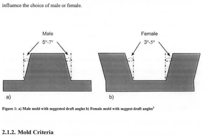
First the decision for a male or female mold is decided. Both mold options are shown in figure 1. This is usually determined mainly by end shape. Both molds forms leave the top portion with a thicker layer of plastic2. Depending on which side of the form requires more strength can influence the choice of male or female.
I
a) b)
Figure 1: a) Male mold with suggested draft angles b) Female mold with suggest draft angJesz
2.1.2. Mold Criteria
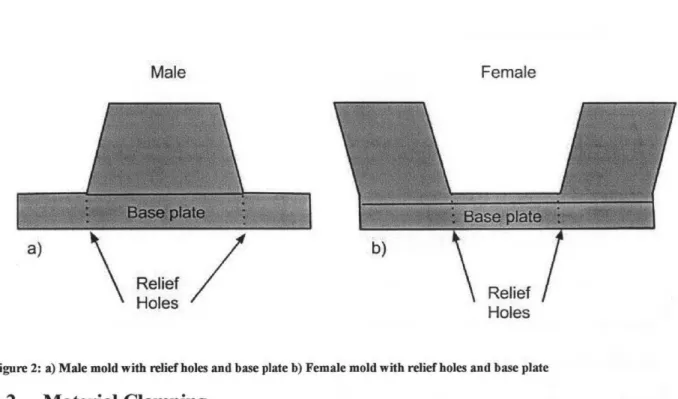
F or a form to be made properly three things need to be in place. First is the draft angle, which is a slight angle of vertical surfaces to help the form release from the mold. This is because most materials used in thermoforming shrink. Because most molds are meant to be reusable draft angles make it possible to separate mold from finished form without damaging either. Second is a Base plate. This ensures that the plastic does not total encase the mold on the 6th surface and allows the mold to be released from the form. Base plates can also add weight to the mold to
allow for easier release. Last is the relief hole. Air can be trapped in pockets between the mold and the form. These holes allow the removal of air pockets to let the form fully conform to the
mold. 2 a) Male Relief Holes Female Holes
Figure 2: a) Male mold with relief holes and base plate b) Female mold with relief holes and base plate 2.2. Material Clamping
After the mold has been constructed, a sheet of forming material is secured in place. This
clamping also creates a seal for the vacuum to function. The frame of the clamp needs to be
strong enough to ensure the sheet is held firmly while resisting the vacuum pressure. Additional it must ensure that it can be adjusted to the different thickness and dimension of the sheet.
2.3. Material Heating
A heat source it place over plastic to the point of phase change from solid to liquid. In order to
" .".~
deformities. Under heating can cause decrease definition of the mold. Heat time is complex to predict and so some trial and error is need to find the appropriate heat time
2.4. Material Pre-stretch
When the plastic is ready for forming, it can be pre-stretched to ensure a more even wall
thickness when the vacuum is applied to the mold. Pre-stretch can be useful when drawing parts with more depth. This is usually performed by a release of compressed air under the sheet.
2.5. Vacuum and Mold Plug
Once the material is pre-stretch, the vacuum can be applied to sheet to form over the mold. Some machines us two stage vacuums to ensure the rapid molding of the heated material. Mold Plugs are optional and can then be used to help further form the sheet to the desired shape. Plugs are usually used when forming multiple impression male molds as they can be situate near each other without the worry of webbing.
2.6. Form Cooling and Release
Once the sheet is formed, it must be allowed to cool before being release from the clamp and the mold. This can be helped by forced cooling with a powered device spraying mist on the mold or
by applying a damp cloth. If the sheet is released too soon it will warp and deviate from the
intended shape
2.7. Form Trimming and Finishing
Now that the sheet is formed, cooled and removed from the machine, excess plastic can be trimmed. Holes, slots and cut-outs can then be performed to get it to the desired final shape. 3. 3D printing Comparison
Additive Manufacturing methods are very capable to make a variety of complex and simple shapes or objects. It also is not limited in the forms that can be made when compared to Thermoforming. The EDS lab only looked at one other option beside Thermoforming and that was 3D printing.
3.1. Cost
The price of 3D printing material is anywhere from $20-$180 per kg dependent on the color and type of plastic'. Comparing this to the price of Sheets of plastic for thermoforming, which range about $1-$10 per kg, we can see one of the drawbacks of the materials of 3D printing4. Additionally the cost of industrial thermoforming can range from $5,000-$20,0002. 3D printers have dropped in price to about a few hundred dollars but these have a very limited foot print. In order to ensure breath of scope for size a larger more expensive model would have to be used and with prices ranging upwards of about $10,000+1.
3.2. Utilization
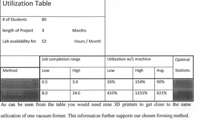
The second factor we compared was utilization. Table 1 gives a breakdown of the utilization that we can expect in a conservative class with 80 students, lab only open from 9-5pm on weekdays
Table 1: A utilization breakdown of ideal project cycle with weekday 9-5 access to lab.
Utilization Table
# of Students 80
length of Project 3 Months
Lab availability for 52 Hours I Month
Job completion range Method r~}@ffi{~itffi~wi~--'l L~-.~~~~-~J ~~ ·~~1~'1-i.~:~~ - , c ' . J I ~ _ _ _ _ _ • _ _ _ > _ _ _ _ _ _ _ _ _ _ _ - _l Low High 0.5 3.0 8.0 24.0 Utilization w/1 machine Low High 26% 154% 410% 1231% Optimal Avg. Stations 90% 821%
As can be seen from the table you would need nine 3D printers to get close to the same utilization of one vacuum former. This information further supports our chosen forming method.
4. Method of Mold Design 4.1. Shape Factors
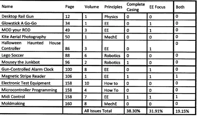
The first determination of mold design is the shape of the mold. Research was done mostly by analyzing project suggestions in Maker Magazine. Table 2 is a breakdown of sample data taken from the magazine.
Table 2: Sample projects with some significant criteria found. Total is for all projects classified from issues 1-345 Name Page Volume Principles Co plete EE Focus Both
- - Casing _
Desktop Rail Gun 12 1 Physics 0 0 0
Glowstick A Go-Go 34 1 EE 0 1 0
MOD your ROD 49 3 EE 0 1 0
Kite Aerial Photography 50 1 MechE 0 0 0
Halloween Haunted House 0
Controller 86 3 EE 0 1
Lego Soccer 88 6 Robotics 0 0 0
Mousey the Junkbot 96 2 Robotics 1 0 0
Gun-Controlled Alarm Clock 100 8 EE 0 1 0
Magnetic Stripe Reader 106 1 EE 1 1 1
Electronic Test Equipment 158 10 How to 0 0 0
Microcontroller Programming 158 4 How To 0 0 0
Midi Control 158 7 EE 1 1 1
Moldmaking 160 8 MechE 0 0 0
All Issues Total 38.30% 31.91% 19.15%
Complete Casing is set as "1" if the project was completely cased. EE focus is set as "1" if the project's main principle discipline was Electric Engineer. As can be seen by the results only about 38.30% were completely enclosed. Of the total "Complete Casing" close 50% of them
criteria. One is that the case totally encloses the standard circuit boards use by the lab. Extra space can be added in case of wiring, capacitors and other components. Next criteria is that since most circuit boards are four sided then rectangle/squares will be the dominate shape needed. Another criterion that becomes obvious is that more shapes will be needed to cover additional
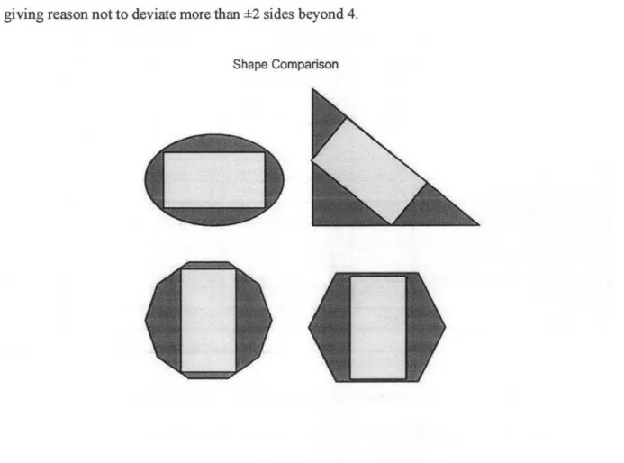
creativity. But these less dominate shapes can't deviate too much on the # of sides as when we
deviate from four sides we end up with more wasted space. This is visually shown in fig. 3 giving reason not to deviate more than ±2 sides beyond 4.
Shape Comparison
Figure 3: a) Shape Comparison with red representing space with high probability of not being used.
4.2. Detail Selection
After the shape choices become apparent, a small amount of detail can be added to some shapes to help the beginners along. In selecting details to be used, three criteria were used. First, the detail could not be too complex in detail because complexity increased the size of mold as thermoforming cannot handle too much small detail. Secondly, the detail can't take up too much of the top surface as this might restrict creativity and multi-purpose affinity of the mold. By looking again at Figure 3 we can estimate that at most 50% of the total surface can be used. So we can designate our neutral or empty space to be 50-100% of the shape surface. Lastly, the details need to belong to themes that will be favorable to MIT students. Acceptable themes could be School Spirit, Generation Tech friendly or part of the Nerdist culture.
4.3. Design Tools
The process used to create mold varied by the shape and detail chosen. The order of design tools used is fairly consistent even with the variations.
4.3.1. Solidworks
Initial CAD models of chosen shapes and details are made to the correct perspective. All similar shapes are kept to the same base dimension for ease of building a mated part for it. After the
Figure 4: a) rectangle shape with EECS logo b) MIT logo with same base dimension as part a. Both use the same baseplate and need the same mated part.
4.3.2. Mastercam X6
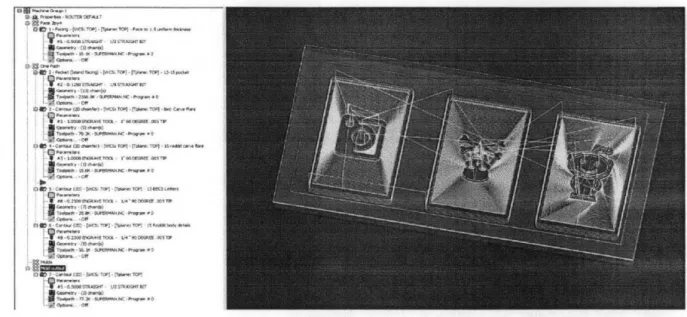
The drawing file is then imported into Mastercam X6. Here tool paths are constructed in Figure 5. The tool paths are then check visually with a computer simulation as can be seen in Figure 6.
Figure 5: Sample constructed tool path done in Mastercam X6. Left are the tools chosen with their respective path type. The right shows the predicted movement of the tools.
4.3.3. Router (Techno or Shark pro)
The G-code is loaded in to a router to do the rough cut of the mold shapes. Most detailing is done here also to ensure the detail is placed correctly on the mold. Several router bits are used in this stage. The material is first faced with a 2.5 facing bit. Initial cuts and outlines of the detail is done with the 1/8" and %A" straight bits. The chamfers and finer detailing is done with the V-60* and V-90* bits. Finally the rough mold is cut out of the material with the longer fluted '2"
straight or 3/8" spherical bits. The base plates are also cut out at this point
4.3.3.1. Router Bit List
a) 2.5" Face bit %" shank w/2 3/4" flutes b) 1/8" Straight bit 1/4" shank w/2 %" flutes c) 1/4" Straight bit /" shank w/2 %"
flutes
d) 1/2" Straight bit A" shank w/2 1.5" flutes
e) 3/8" Spherical bit %" shank w/1 2" flute
f) 1" V-60* %" shank w/2 1" flutes g) 1/2" V-900 %" shank w/2 1" flutes
4.3.4. Hand and Belt Sanders
The rough molds are not sanded to remove any flash or burs. Non-straight edges are finish here
by using the sander at a 70 angle to apply an initial draft. This is follow by hand sanding with
papers and files to smooth out the drafts and remove any burs in the detail. At this stage the base plates are also sanded my the hand and belt sanders to remove any burs from the material
4.3.5. Table Saw
The last design tool is a table saw. A flat edge jig is made to facilitate cutting a 7* draft angle on straight edges. This jig allows a consistent draft to be made with minimal effort and maximum safety.
4.4. Material Selection
Choice of material of Mold had a few top choices. Aluminum was foremost of options for the mold but due to the restrictive availability of machining tools in the EDS lab it was not used. One goal was to have the molds easily repaired and/or remade from scratch. To use Aluminum as a material the lab would need a CNC milling machine at a minimum. The only CNC machine in the lab was a router. With this in mind a polyurethane-based thermoset foam board was used called Renshape® 5025. The price of Renshape per kg is slightly higher but, with its machinability being better that wood, made this the perfect choice. The base plates were also not made out of Aluminum for the same reason as the mold. Weight was durability were the main factors in this part so wood was chosen. Ply would seem to best fit the need so a no gap Lauan plywood was used to keep the structural integrity of the base in a vacuum.6
4.5. Quality Control
Quality control was performed once the machining process was complete. Step 1 involved the use of a Caliper to verify the critical dimensions. The critical dimension depends on the stock shape of the mold. This ensures that all similar shapes would be of the same dimension and could therefore reduce the number of configurations of bases that needs to be prepared for the form. Step 2 of quality control was to use an Angle Block to verify the 70 Draft for easy release. If either step failed by more than 5% accuracy the mold would be sanded by hand till verification was met.
5. Mold Design
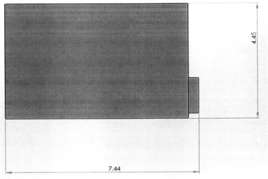
The molds that will be used in the EDS lab had to have the capacity to fit a circuit board made for the project classes that are being held there. Figure #### shows a solid work sketch of the dimensions of the EDS lab Custom circuit board or EDS-board.
7.44
Figure 7: Dimensional Schematic of Custom Circuit Board made for EDS lab (EDS-board).
With this as the main criteria for restrictive dimensions, 5 Circuit schemes were formulated and are reflected in the naming schemes of all drawings in Appendix A. OC is for any mold that the EDS-board would not fit. This was chosen to accommodate small independently chosen boards like some of the popular microprocessors (i.e. Arduino.) The IC scheme is designate for any shape that can comfortably fit one EDS-board. 2CP is the designation for a mold that can hold two EDS-boards arranged in parallel to each other. 2CS is the designation for a mold that can hold two EDS-boards stacked one on top the other. Finally 4CSP is the scheme that can hold 4 EDS-boards in a 2x2 stacked formation. These 5 Schemes, combined with 7 choices shapes and
6. Conclusion
The aim of a class with Engineering Design points is to help the student learn how to put in to practice different lessons and techniques in engineering a product. Beginner machinist are sometimes held back by the time consuming process of constructing proper housing for electronic dominant disciplines. The aim for this thesis was to devise a simple multi-use molding system to facilitate learning for the beginner machinist.
Five schemes were used in conjunction with seven shapes and sixteen different detail designs to come up with thirty seven molds that students can use in many different ways. Choosing Renshape* , a polyurethane based thermoset foam, for the mold allows the limited facility in the
EDS lab to repair and manufacture a variety of mold designs. With the addition of a plywood
base board for added weight and grip, allows the forms to be easily removed and reuse the molds.
In the future if a CNC mill is ever added to the Lab, The molds can be easily remade and maintained in Aluminum using the G-Code already generated. Wood can also be used to remake molds but its machinability is not as good as that of the foam but its durability is better for a longer lasting mold core.
7. References
1. 3ders.org - price compare 3D printing materials. (n.d.). Retrieved February 01, 2014, from
http://www.3ders.org/pricecompare/ 2. Formech. A Vacuum Forming Guide.
3. Lienhard, J. H. (2010). Heat Transfer. Journal of Heat Transfer, 82(1), 198.
doi: 10.1115/1.3246887
4. Plastipedia: The Plastics Encyclopedia - Vacuum Forming. (n.d.). Retrieved January 31, 2014, from http://www.bpf.co.uk/plastipedia/processes/vacuum-forning.aspx
5. Maker Media. Maker Magazine, 1-34. Retrieved from www.makezine.com 6. Technology, H. A., & Center. Renshape Properties. Retrieved from
Appendix
Appendix A: Model Drawings
7.93 1.6
Ii
4 4 C> 8.00 s_UNLESS OTHER WISE SPECIFIED: IFINISH: DEBUR AND
DIMENSIONS ARE IN MILLNMETERS 'BREAK SHARPDONTCAERANGEVSN
SURFACE FINISH: EDGES
TOLERANCES: LINEAR:
ANGULAR:
NAME SIGNATURE DATE
TITLE-'DRAWf :CHCD APPVD" WF -- 6idW&WStUd'ht Edit!66 Engcdmi UA DWG NO. 4C :4 R EC
1> 0. 224 8.8 Cl, 0 a co 0.4 0..26 0 0.46 1.33
o e
-o
uw
w
~r mm
aw
xa
a g
w
w w
as
r o
~me
w-&
vmm
m
n
m neae
ww
m m
m
-n -mm
m
m
n ow
'an
m m
a
n~es
e m
n
u-t
m
a
x.-w
s
m
le
m
'wml-
s
*m
4. 00 N
93om
I- ' 00 (Y) (2 0 0 92*0 001 (), 6*09
0
00 0g
oA L-0 00 oo 0 NS2 to 0 -ci U er
r Cc C cm- <-I4,KQ
93 O uuo< 93 0 9 -O L . z m< &II
9t wen .Mo 1.39
rn~'-100
to 710.25 00 60 OO .0i 4 4.18
1
0.86 N. co C5-6.29 0 L_() C\4 03 0-i--i
UNLESS OTHERWISE SPECIFIED: FINISH: DEBUR AND
DIMENSIONS ARE IN MILLIMETERS BREAK SHARP
SURFACE FINISH: EDGES
TOLERANCES: UNEAR: ANGULAR:
NAME SIGNATURE DATE
DRAWN4
ICH K'D
rAPPV'D
MFG S6IicW6rk StUfde
n
mhA EorAcadeni icWEn
ny.
WEJGHT:
DO NOT SCALE DRAWING REVISION
TITLE DWG NO.
Superman-IC
A4CF SCALE:1S SHEETS5OF 43 cO I M M I yx y2.8
0425 1.00 7 0.38 LAa3.07 LC) (N 03 *1I S 2.65, 0-65 RO.32 N 00 RO.24 0 e -0.96 1.06 1.04 U-0 0 9
UNLESS OTHERWISE SPECIFIED: FINISH: DEBURAND
BREAK SHARP DO NOT SCALE DRAWING REVISION
SURFACE FINISH: EDGES
TOLERANCES: UNEAR: ANGULAR:
NAME SIGNATURE DATE TITLE:
DRAWIf
"CHMT
tAPPVDM
SG
ofi
ors
StudentEditiio
Q A rAcademicAJSW~nly. DWGNO.
WEIGHT: SCALE:1:5 SHEET 7 OF 43
A
FTZ 1 ~IAA n *-M r4 s >= ~~g -z " 0 A 0.25 O a--P/ -0 Cr0 01________________ 1.44 1.57 0 0.33 '.uu I-a 0.54 1.36 ).67 2.25
3.00
(A 003.05 1.62 1.33 .30
C5II
0O9
3.06a
r. 4.80Sz z A
m Im
iN 6 N nQ nr or, > m C 00 FC & 8.00 -1 -n E4 tO0 0 (Nry LC) dn (N I
-t:!
8.00
0C) 0 0 6)I
I
0,/U t7 * J7 -(D e-Z 0cp -Li-Li (zacIl z 00. 4L CNo Im- -*--a y, 9 0LL 6Q -< <: i-21 < ff Uz am -Z oc<-7.41 0 I LO 0o
8.0i.
C\ Q4 4
UNLESS OTHERWISE SPECIFIED: FOIH EBUR ANDDONTSAERWIGEVIN
DIMENSIONS A RE IN MILLIMETERS BREAK SHARP D O CL R IGRVSO
SURFACE FINISH:
EDGES-TOLERANCES:
LINEAR: t
ANGULAR:
NAME SIGNATURE DATE
'TITLE-PRAWN
CHrD APPVD,
ci FM i s- Je" "E di t i
E.._or kcad. ijr, U Only. i;DWG NO.
- -. A4
WAE 4
SCL:: F4 4HE4S
WEIGHT'
0 0 0 (Y) F
'Ii
4,; 44I
I
Ii
iiII
~ I
94 I'If
4 ~ ~ 4ii
~:
~
4 4 II
I II I
41 8.00 TRUE RO.10 CD (N 0ML
11.4 NO NO 4 11.66 No 00
UNLESS OTHERWISE SPECIFIED: FINISH: DEBUR AND
DIMENSIONS ARE IN MILLIMETERS BREAK SHARP DONOTSCALEDRAWING REVION
SURFACE FINISH: EDGES
TOLERANCES:
LINEAR:
ANGULAR:
NAME SIGNATURE DATE TTLE
' CHCD 'APPVD
MFG
IrdWo-RS Si
dnt Edt ion
A Er-Academic
U
nly
DWGNO.-nly. A4
WEIGHT: SCALE:1:5 SHEET 17 OF 43
0
000
0
I'Ig7*
-O (qN 0.84
Ii
r-. e-iUNLESS OTHERWISE SPECIFIED: FINISH: DEBUR AND
DIMENSIONS ARE IN MILLIMETERS BREAK SHARP DO NOT SCALE DRAWING REVISION
,SURFACE FINISH: 'EDGES TOLERANCES:
LINEAR:
ANGULAR:
NAME SIGNATURE DATE TITLE: DRAW9 CHKD APPV"D MFG
SohdWorRsfu dnt
Edition EWEIGHTne y DWG NOSE9 A4 WEIHT:SCALE:5' SHEET 19 OF 43 0.90 17. 001 0 6.86 LO Br-C"4 C3 CDT Y0
a
5
2n88 O0
i
UNLES I EE FINISH: DEBUIRAND
DIMENSIONS AaRE IN MILLMETERS BREAK SHARP DO NOT SCALE DRAWING REVISION
SURFACE FINISH: EDGES -
--TOLERANCES: LINEAR: ANGULA R:
a AME S TURE !DAE TTLE:a
" RAWN
4 APPVDI
~W S i ksFuS i
Q.Ar c da iOny DWG NO.
47
2iZ.
-474
44
0-Go C 0 1-1 T1 0\ $ c3I ~
ii
U I 3 3 I I ~1 I I TRUE RO.1 . 1.25 1.2L 1 1.7C 2.95 0 00o.91 5.43
cp
20
UNLESS OTHERWISE SPECIFIED: FINISH: DEBUR AND DIMENSIONSAREINMILLIMEERS BREAKSHARP
SURFACE FINISH: EDGES
TOLERANCES:
UNEAR: ANGULAR:
NAME SIGNATURE DATE
ICHKD
bAW4
SolidiG
orks
itudentEion
or
-cadeic Ed W UWEOGHT: y 1.20-7-
F
C)) 2.50 2.16 0 Cy CNo 8.7DO NOT SCALE DRAWING REVISION
TITLE:
DWGNO.A
Superman-2CP
1 ]. C0
00
C c c CO J L-0C
ci (N) 0\Cp
61
co 02? (N 4.05 LC)2.39 NC 6 0 N-. 2.08 , L I I T- I (N NO 6-0 c6 00 0.55 . 0 5.93 00
UNLESS OTHERWISE SPECIFIED: FINISH: DEBUR AND
DIMENSIONS ARE IN MILLIMETERS BREAK SHARP DO NOT SCALE DRAWING REViSON
iSURFACE FINISH: EDGES fTOLERANCES:
UNEAR: ANGULAR:
NAME SGNATURE DATE TITLE:
DRAW4 'CHKIDj IAPPVDi FG
dIIW W
i
W
tEdItion..
.A-Fon'rAcademi~c-U F
W O 1r c nl.DWGNO.Beaver-2C
P
WEG: SCALE:1:5 SHEET 25 OF 43
10100
-r- I
Dj
)0
F-10.00
00
9.69
0
'UNLESS__ OTEWS PCFE: IIH EU N
gD__________ARE miuETEs IN BREAKSHARP DO NOT SCALE DAWtIG REVISIO
C\1RAC
FIIH DE
C,-) Lo~ c 5.90 cl) LO 65 0 '4 0 0 0 0
I-
I -
10.00
eUNLESS OTHERWISE SPECIFIED: ,FINISH: DEBUR AND
DIMENSONS ARE IN MILLIMETERS BREAK SHARP
SURFACE FINISH: iEDGES -TOLERANCES:
UNEAR: ANGULAR:
NAME SIGNATURE DATE
TITLE-,DRAWN
APPVD.
ilFG j -So1idW
orks1~ucle-ntEdition.
ocademi_
fOnly.
DWG NO.-AA WUE~nIG AWEN-
iHackintosh
2CR
IA452,
I WEIGHT: SCALE:5 SHEET 27OF 43
3-0 Lr)cl 4
008
QQ47
> a A -M zzf 01 0 1 1
TFI
* dcnf
5.00 V 15 eFn 8 1 10CM
00 ic~) t~i-I
4.7815.36 4 0 cg 16.00 11
667 o C) I-z < V a i zz Z4A Z <z oL* u
y
(/L @0LA(
15.72
16.00
].
22-81 3.13 7.59 LtL) o a 3.33 8.08 060 Lr)) 0
UNLESS OTHERWISE SPECIFIED: IFINISH: DEBUR AND
DIMENSIONS ARE IN MILLIMETERS BREAK SHARP DO NOT SCALE DRAWING REVISION
SURFACE FINISH: EDGES
TOLERANCES:
LINEAR:
ANGULAR:
NAME SIGNATURE DATE TITLE
DRAW4 .CHKD
IAPPVDl
Fi
or
oI
sSti dt
on.
-GA
ForAcademic
U.WOnly. DWN0C
19V
9~
P Q.72, 2.03 2.1 ON 0-5 93
UNLESS OTHERWISE SPECIFIED: FINISH: DEBUR AND
DIMENSIONS ARE IN MILLIMETERS 6BREAK SHARP DO NOT SCALE DRAWING IREVISION
ISURPACE FINISH: EDGES
6TOLERANCES:
ANGULAR R:
NAME SIGNATURE DATE TITLE ORAWF4I
C
60
0 0 N.. 3.2 . 1.21 JRUE RO.10 1.19 0.59 C9 10.50 5.99 0 0 2.91 10.30 .80 1.05 0
1.80 1.40
1.89
DIENIGSAR I I IETERS
TRU RO.1 0po
'UNLESS OTHERWISE SPECIFIED: ; FINISH: DIMENSIONS ARE IN MILLIME17ERS
ASURFACE FINISH: TOLERANCES: UNEAR: ANGULAR: NAME SIGNATURE D DRAW CHED APPVD' FG E o -OCSa A -. Eor Acadm ic 9.60 0
0
CY) 04.L244~
16-80t
C\4 DEBUR ANDBREAK SHARP DO NOT SCALE DRAWING REVISION EDGES
IATE TITLE:
U dent E-cit i6
UfOnly. DWGNO.
WEIGHT: SCALE:1:5 SHEET 37 OF 43
35
- -1.25 Lo TRUE RO.10 14 10.50 5.99 IC3 V. ,) *0 q-i ~ I I
Ii
II
I I I I Ii 1 1 I i 9.83(r0
I1
72
ii
I
I
Ii-(N0
UNLESS OTHERWISE SPECIFIED: FIIH
IU
NDOMS NOTSCLEDRWRA RVIIO OJISINS ARE IN MILMETERS BREAK SHARP DNTCLDAIGRVSO
SURFACE FINISH:EGSq TOILERANCES
LINEAR:
ANGULAR:
NAME SINTR AETITLE: ODRAWF4
APPVD~
GA I or Academic UEOnly. DGOI mDr~) A4
2.62 1108
-0
IN
03 -0 a'C
(N 0p_
3.97S. 0.55IF
11 01 0P 00
f 6UNLESS OTHERWISE SPECIFIED: VFINISH: DEBUR AND
DIMENSIONS ARE IN MILLIMETERS BREAK SHARP DO NOT SCALE DRAWING REVISION
SURFACE FINISH: EDGES
TOLERANCES-LINEAR:
ANGULAR:
NAME SIGNATURE DATE TILE:
DRAWNf
'HD
*APPVD $
FG SOhdWrkS Mu ff tl
Q-A
EoA
caden.tU WOnly.
WG~DWGNO.
Su perma n-2C8
A- 66
033 03 2.13 TRUE RO.10 1.00 1.0 1.0 1.27 0.7 970
2.77 66 0* Lo 65 10.00 0? 1.40 1.2 2.88 Lo (N1 d C0 C9
$1
UNLESS OTHERWISE SPECIFIED: FINISH: DEBUR AND
DIMENSIONS ARE IN MILLIMETERS BREAK SHARP DONOTSCALEDRAW1NG REViSION
ISURFACE FINISH: EDGES
TOLERANCES: UNEAR ANGULAR
NAME SIGNATURE DATE TITLE:
DRAW4
iCHK'D
iAPPVD I
MFG SoldWorks
Student Edition,
laA or Ac
ad
emn y.
DWG NO.ADWGNO:
EECS-4CS P
I iWEIGH 1 SCALEA15 SHEET 43OF 43
0.79
I
4.00 Q 0 9 0 0 9.00 L) CN
UNLESS OTHERWISE SPECIFIED: FINISH: DEBUR AND
DIMENSIONS ARE IN MILLIMETERS BREAK SHARP DO NOT SCALE DRAWING REVMSION
SURFACE FINISH: EDGES
,TOLERANCES:
LINEAR:
ANGULAR:
NAME SIGNATURE DATE TITLE:
DRAW4 *CHKD
FG
S
Wrks
6nfuciet
Edfi6i
Ear ic ade SWEDWG NO.
4:C:: HETA4
0 0) )O 9.00 T ~ TI ~ I ~ I
7.00 0 0 0 0 9.00 Lc) C\N 6
UNLESS OTHERWISE SPECIFIED: FINISH: DEBUR AND
DIMENSIONS ARE IN MILLIMETERS BREAK SHARP DO NOT SCALE DRAWING REISION
SURFACE FINISH: EDGES
JTOLERANCES:
LINEAR:
ANGULAR
NAME SIGNATURE DATE TITLE
DRAWI
'CHK'D iAPPVD.
TSlidWorks 5 dnt Edition
OA3 _F-nrA cadernic-sWOnly. DWGNO
WEiGim
TCAE:y:-rEc
I
c
A4 1
mn
F
-isY
4.31
15.00
UNLESSOTHERWISESPECIFIED: FINISH DEBURAND
DIMENSIONS ARE IN MILLIMETERS BREAK SHARP DO NOT SCALE DRAWING REVISION
SURFACE FINISH: EDGES
TOLERANCES: UNEAR: ANGULAR:
NAME SIGNATURE DA TITLE
~DRAW
-HK'D JAPPVDr
G OrKS kOIldV
StidentEdio n
-
For Acadenpi
onIy
DWG NO5 A4-74A
c 10.45 mo 0-L6 14.97 LO0 IN 65
9.00
E
I
15.00
UNLESS OTHERWSE SPECIFIED: FIN H DEBUR AND
DIMENSIONS ARE IN MILLIMETERS BREAK SHARP DO NOT SCALE DRAWING REVISION
SURFACE FINISH: EDGES
TOLERANCES:
ANGULAR:
NAME SIGNATURE DATE TITLE
DRAW4,
IAPPVD
MFG
r
S
NTorks
~biiEditEAo
A cadem" E DWG NO.- A4
E5by
5-rec2c
LA
15.00
9.00
0a
0
0
15.00
LO)
UIMNSI S RWE N E INIS H BRA DHR DO NOT SCALE DRAWING REASION
SURFACE FINISH:
EDGES--TOLERANCES:
LIUNEAR:
AE SIGNATURE DATE TITLE:
,DRAWi
JAPPVD i
11 1
oF Oi Yors Studenft Et n
A"
~o caden tCU 64E -ny DWG NO.15by 15-suare2_
8.40 1.00 0.80
4
0 po k-. 0Y 15.00 Lo 0" 0fl 13 0 ~ A 0 A 3 0 ~ 0112.8 0 0 0i C"4 0 0 20.00
UNLESS OTHERWISE SPECIFIED: FINISH: DEBUR AND
DIMENSIONS ARE IN MILLIMETERS BREAK SHARP DO NOT SCALE DRAWING REVISION
SURFACE FINISH: EDGES
TOLERANCES
LINEAR:
ANGULAR:
NAME SIGNATURE DATE TITLE:
DRAWR CHrD
,APPVDf
G oS 0- o rks btu-dition
EQAcade Onl. DWGNO
y- A4
WEGEo:
SCALE
1:1S20by20-tri
I
cA
WEIGHT- SCALE:O SH10EET IlOF I
Appendix C: Sample G-Code
(PROGRAM NAME -SAMPLEGCODE) ( 1/4 STRAIGHT BIT TOOL -1 DIA. - .25)
N100TlM6 N110S18000M3 N120G0G90X14.9651Y87.3054Z2. NI30Z.I N140G1Z-.25F100. N150X14.9612Y87.419F200. N160X14.9498Y87.5281 N170X14.9309Y87.637 N180X14.9044Y87.7457 N190X14.8701Y87.8542 N200X14.8279Y87.9622 N210X14.7778Y88.0698 N220X14.7196Y88.1768 N230X14.653Y88.283 N240X14.5781Y88.3881 N250X14.4947Y88.4919 N260X14.4026Y88.5942 N270X14.3019Y88.6946 N280X14.1924Y88.7927 N290X14.0743Y88.8883 N300X13.9475Y88.9808 N310X13.8122Y89.0699 N320X13.6687Y89.1552 N330X13.517Y89.2363 N340X13.3576Y89.3128 N350X13.1909Y89.3841 N360X13.0171Y89.45 N370X12.8369Y89.5101 N380X12.6509Y89.5639 N390X12.4595Y89.6113 N400X12.2636Y89.6518 N410X12.0637Y89.6852 N420X11.8607Y89.7113 N430XI 1.6554Y89.73 N440X1 1.4485Y89.7412
N520X9.8145Y89.5545 N530X9.6265Y89.4985 N540X9.4448Y89.4363 N550X9.2701Y89.3681 N560X9.1028Y89.2945 N570X8.9433Y89.2159 N580X8.792Y89.1327 N590X8.6491Y89.0454 N600X8.515Y88.9543 N610X8.3896Y88.8601 N620X8.2732Y88.763 N630X8.1658Y88.6635 N640X8.0673Y88.562 N650X7.9777Y88.4588 N660X7.8968Y88.3543 N670X7.8245Y88.2487 N680X7.7608Y88.1424 N690X7.7053Y88.0355 N700X7.658Y87.9282 N710X7.6185Y87.8208 N720X7.5869Y87.7132 N730X7.5629Y87.6056 N740X7.5463Y87.4981 N750X7.5371Y87.3901 N760X7.535Y87.3065 N770G2X7.41Y87.18471-.125J.0032 N780G1X6.255 N790Y86.3536 N800G2X6.13Y86.22861-.125J0. N810G1X4.654 N820Y81.0347 N830X17.8452 N840Y86.2286 N850X16.37 N860G2X1 6.245Y86.353610.J. 125 N870G1Y87.1847 N880X15.09 N890G2X14.9651Y87.305410.J. 125 N900G1Z.IFI00. N910G0Z2. N920X1.25Y94.8747 N930Z.1 N940G1Z-.25 N950X10.2502F200. N960X10.2702Z-.23 N970X 11.2302 82
N98OXI1.2502Z-.25 N990X21.25 NI 000G2X21.375Y94.749710.J-. 125 Ni01OGiY85.9377 N1020Y85.9177Z-.23 N1030Y84.9577 N1040Y84.9377Z-.25 N1050Y74.7497 N1060G2X21.25Y74.62471-.125J0. N1070GiX11.6852 N108OX11.6652Z-.23 N1090XIO.7052 NI 100X1.6852Z-.25 N11IOX1.25 N1 120G2X1. 125Y74.749710.J. 125 NI 130G1Y94.7497 N1 140G2X1.25Y94.8747I. 125J0. N1150GIZ.IFIOO. N1160G0Z2. N 1i70X42.8899Y87.9966 NI18OZ.I NI 190GIZ-.23 N1200X42.4099F200. N121OX42.3899Z-.25 N1220X37.0212 N1230X37.0012Z-.23 N1240X36.0412 N1250X36.0212Z-.25 N1260X31.0274 N1270X31.0074Z-.23 N1280X30.6101 N1290X30.9616Y87.5573 N1300X30.974iY87.5416Z-.25 N1310X36.4377Y80.7122 N1320X36.4502Y80.6965Z-.23 N1330X36.75Y80.3217 N1340X37.0499Y80.6965 N1350X37.0624Y80.7122Z-.25 N1360X42.5776Y87.6062
N1440X46.75F200. N1450G2X46.875Y94.749710.J-. 125 N1460G1Y74.7497 N1470G2X46.75Y74.62471-.125J0. N1480G1X26.75 N1490G2X26.625Y74.749710.J. 125 N1500G1Y94.7497 N1510G2X26.75Y94.87471.125J0. N1520G1Z.iFiOO. N1530G0Z2. N1540X45.125Y67.6247 N1550Z.1 N1560GIZ-.25 N1570X38.375F200. N1580Y63.8747 N1590X45.125 N1600Y67.6247 N161OZ.1F100. N1620G0Z2. N1630X37.25Y70.3747 N1640Z.1 N1650G1Z-.25 N1660X46.25F200. N1 670G2X46.375Y70.249710.J-. 125 N1680GiY61.2497 N1690G2X46.25Y61.12471-.125J0. N1700G1X37.25 NI71OG2X37.125Y61.249710.J. 125 N1720G1Y70.2497 N1730G2X37.25Y70.37471.125J0. N1740GIZ.IFOO. N1750G0Z2. N1760M5 N1770M30 84