UNIVERSITÉ DE NEUCHÂTEL
Splay: A toolkit for the design and
evaluation of Large Scale Distributed Systems
Thèse
présentée le 27 juin 2014 à la Faculté des Sciences de l’Université de
Neuchâtel pour l’obtention du grade de docteur ès sciences par
Lorenzo Leonini
acceptée sur proposition du jury:
Prof. Pascal Felber
Université de Neuchâtel
directeur de thèse
Prof. Peter Kropf
Université de Neuchâtel
rapporteur
Dr Etienne Rivière
Université de Neuchâtel
rapporteur
Prof. Vivien Quéma
INP, Grenoble
rapporteur
Faculté des sciences Secrétariat-décanat de Faculté Rue Emile-Argand 11 2000 Neuchâtel - Suisse Tél: + 41 (0)32 718 2100 E-mail: [email protected]
IMPRIMATUR POUR THESE DE DOCTORAT
La Faculté des sciences de l'Université de Neuchâtel
autorise l'impression de la présente thèse soutenue par
Monsieur Lorenzo LEONINI
Titre:
“Splay: A toolkit for the design and evaluation of Large
Scale Distributed Systems”
sur le rapport des membres du jury composé comme suit:
• Prof. Pascal Felber, Université de Neuchâtel, directeur de thèse • Prof. Peter Kropf, Université de Neuchâtel
• Dr Etienne Rivière, Université de Neuchâtel • Prof. Vivien Quéma, INP, Grenoble, France
• Prof. Spyros Voulgaris, VU University, Amsterdam, Pays-Bas
Acknowledgements
First, I would like to thank my adviser, Prof. Pascal Felber, for all his guiding, advice, understanding and for our many shared sporting activities during my PhD studies.
I would also like to thank Dr. Etienne Rivière for our collaboration and all the nice moments spent together.
A special thank to my delicious office mate, Sabina, for her humor, patience and great discussions.
Another special thank to Prof. Peter Kropf for all his threats encourage-ment.
Finally, I want to thank all my professors, colleagues and friends at the Computer Science Department for the great moments at the university and outdoors.
Abstract
Keywords: Distributed Systems, Distributed Algorithms, Peer-to-peer network, LSDS, Large Scale Experiments, Deployment, Sandbox, Simula-tion, Gossip-based disseminaSimula-tion, Epidemic algorithm, Relevance feedback
This thesis presents Splay, an integrated system that facilitates the design, deployment and testing of large-scale distributed applications.
Splay covers all aspects of the development and evaluation chain.
It allows developers to express algorithms in a concise, simple language that highly resembles pseudo-code found in research papers. The execution environment has low overheads and footprint, and provides a comprehensive set of libraries for common distributed systems operations.
Splay applications are run by a set of daemons distributed on one or several testbeds. They execute in a sandboxed environment that shields the host system and enables Splay to also be used on non-dedicated platforms, in addition to classical testbeds like PlanetLab or ModelNet.
We illustrate the interest of Splay for distributed systems research by covering two representative examples. First, we present the design and evaluation of Pulp, an efficient generic push-pull dissemination protocol which combines the best of pull-based and push-based approaches. Pulp exploits the efficiency of push approaches, while limiting redundant mes-sages and therefore imposing a low overhead, as pull protocols do. Pulp leverages the dissemination of multiple messages from diverse sources: by exploiting the push phase of messages to transmit information about other disseminations, Pulp enables an efficient pulling of other messages, which themselves help in turn with the dissemination of pending messages. Finally, we present the design and evaluation of a collaborative search com-panion system, CoFeed, that collects user search queries and accesses feed-back to build user and document-centric profiling information. Over time, the system constructs ranked collections of elements that maintain the re-quired information diversity and enhance the user search experience by presenting additional results tailored to the user interest space.
Résumé
Mots-clés: Systèmes distribués à grande échelle, Algorithmes distribués, Réseaux pair à pair, Expérimentations à grande échelle, Déploiement, Bac à sable, Simulation, Algorithmes épidémiques
Cette thèse présente Splay, un système intégré qui facilite la conception, le déploiement et les expérimentations des systèmes distribués à grande échelle. Splay couvre toutes les étapes du développement à l’évaluation. Il permet à des développeurs d’exprimer des algorithmes de manière simple et concise dans un langage proche du pseudo-code que l’on peut trouver dans les publications scientifiques. L’environnement d’exécution est léger et fournit un ensemble de librairies répondant aux principaux besoins pour la conception de systèmes distribués.
Les applications Splay sont exécutées par un ensemble de processus dis-tribués sur un ou plusieurs systèmes de test. Ils exécutent ensuite l’application au sein d’un environnement confiné, ce qui permet d’utiliser Splay sans risques même sur des plates-formes non dédiées en plus des environnements classiques tels que PlanetLab ou ModelNet.
Nous illustrons l’intérêt de Splay pour la recherche sur les systèmes dis-tribués à l’aide de deux exemples représentatifs.
Tout d’abord, nous décrivons la conception et l’évaluation de Pulp, un protocole de dissémination efficace qui combine le meilleur des approches “pousser” et “tirer”. Pulp exploite l’efficacité de l’approche “pousser” tout en en limitant la redondance par l’usage de l’approche “tirer” dont la fréquence est conditionnée par des informations complémentaires jointes aux paquets de données.
Finalement, nous présentons la conception et l’évaluation d’un système d’aide à la recherche, CoFeed, qui collecte les recherche des utilisateurs et les accès effectués afin de construire un profil d’utilisateur et de documents. Au fil du temps, le système crée des collections triées de documents qui per-mettent d’améliorer la qualité des recherches en fournissant des résultats complémentaires correspondant aux domaines d’intérêt de l’utilisateur.
Contents
1 Introduction 1
1.1 Context . . . 1
1.2 Contributions . . . 3
1.3 Organization of the Thesis . . . 5
2 Context 7 2.1 The Advent of Distributed Systems . . . 7
2.1.1 Mainframe computers . . . 7
2.1.2 Early years of Internet . . . 8
2.1.3 Commercial Web Advent . . . 9
2.1.4 Google: Scaling with the Web . . . 10
2.1.5 Big Data Challenge . . . 10
2.1.6 Mobile Computing . . . 11
2.2 Distributed Systems Characteristics . . . 11
2.2.1 P2P Systems . . . 13
2.2.3 The CAP Theorem . . . 15
2.3 Distributed System Design . . . 16
2.4 LSDS in Industry . . . 18 2.4.1 Introduction . . . 18 2.4.2 GFS . . . 19 2.4.3 MapReduce . . . 22 2.4.4 Chubby . . . 23 2.4.5 BigTable . . . 24 2.4.6 Splay Applicability . . . 26 2.4.6.1 GFS . . . 26 2.4.6.2 MapReduce . . . 26 2.4.6.3 Chubby . . . 27 2.5 Related Work . . . 28 2.5.1 Development tools . . . 28 2.5.2 Deployment tools . . . 29 2.5.3 Testbeds . . . 30
3 The Splay Framework 31 3.1 Overview . . . 31
3.2 Controller . . . 33
3.2.1 Controller’s Processes . . . 35
3.3 splayd . . . 36
3.4 Deployment . . . 38
CONTENTS 3.5 Splay Applications . . . . 42 3.5.1 Lua . . . 42 3.5.2 The Scheduler . . . 46 3.5.3 The Libraries . . . 48 3.5.3.1 Networking . . . 48 3.5.3.2 Virtual Filesystem . . . 49
3.5.3.3 Events, Threads and Locks . . . 50
3.5.3.4 Logging . . . 51
3.5.3.5 Other libraries . . . 51
3.6 Remote Procedure Call . . . 52
3.6.1 Implementations . . . 53 3.6.1.1 TCP . . . 53 3.6.1.2 UDP . . . 54 3.6.1.3 TCP pool . . . 56 3.6.2 Usage . . . 56 3.6.2.1 Error detection . . . 56 3.6.2.2 Timeouts . . . 57 3.6.2.3 Callbacks . . . 58
3.7 Developing Applications with Splay . . . . 59
3.8 Churn Management . . . 63
3.8.1 Synthetic Language . . . 64
3.8.2 Controller’s Job Trace . . . 65
3.9 Sandboxing . . . 66
3.9.1.1 Language-level Virtual Machines . . . 69
3.9.1.2 Unix-like Security Mechanisms . . . 69
3.9.1.3 Unix Isolation . . . 70
3.9.1.4 Library Interposition . . . 71
3.9.1.5 Emulation and Virtualization . . . 71
3.9.1.6 Language Level Sandboxing . . . 71
3.9.1.7 Summary . . . 72
3.9.2 The Splay Sandbox . . . . 72
3.9.3 Google NaCL (Native Client) . . . 74
3.10 SplayWeb . . . 75
3.11 Summary . . . 77
4 Evaluation of Splay 79 4.1 Introduction . . . 79
4.2 Development complexity . . . 80
4.3 Testing the Chord Implementation . . . 81
4.3.1 Chord on ModelNet . . . 82
4.3.2 Chord on PlanetLab . . . 83
4.4 Splay Performance . . . . 84
4.5 Complex Deployments . . . 86
4.6 Using Churn Management . . . 87
4.7 Deployment Performance . . . 89
4.8 Bandwidth-intensive Experiments . . . 90
CONTENTS
4.8.2 Dissemination using trees . . . 91
4.8.3 Long-running experiment: cooperative Web cache . . . 92
4.9 Summary . . . 93
5 PULP 95 5.1 Introduction . . . 95
5.1.1 Evaluation Metrics and Objectives . . . 97
5.1.2 Contributions . . . 98
5.1.3 Outline . . . 98
5.2 The Push-Pull Dilemma . . . 99
5.2.1 Push protocols . . . 99
5.2.2 Pull protocols . . . 100
5.2.3 Coverage versus redundancy . . . 100
5.2.4 Delay . . . 103
5.2.5 Discussion . . . 103
5.3 The Pulp Protocol . . . . 104
5.3.1 System Model . . . 104
5.3.2 Supporting Mechanisms . . . 104
5.3.3 Pulp: The Intuition . . . . 106
5.3.4 Pulp: The Protocol . . . . 107
5.4 Evaluation . . . 110
5.4.1 Experimental Setup . . . 110
5.4.2 Homogeneous Settings and Churn Resilience . . . 111
5.4.4 PlanetLab Experiments . . . 116
5.4.5 Comparison to Push-only and Pull-only Disseminations . . . 121
5.5 Related Work . . . 124
5.6 Summary . . . 126
6 Collaborative Ranking and Profiling 129 6.1 Introduction . . . 129
6.2 Overall Architecture . . . 134
6.3 Profiling, Storing and Ranking . . . 134
6.3.1 Profiling user interests . . . 135
6.3.2 Collecting interest feedback . . . 137
6.3.3 Managing repositories . . . 137
6.3.4 Item ranking . . . 137
6.3.5 Garbage collection . . . 138
6.4 Distributed Storage System . . . 138
6.4.1 Routing . . . 139
6.4.2 Load balancing . . . 140
6.5 Evaluation . . . 144
6.5.1 User-centric ranking effectiveness . . . 144
6.5.2 Repository peak performance . . . 147
6.5.3 Routing layer . . . 148
6.5.4 Delegation-based load balancing: efficiency and reactiveness . . 149
6.6 Related Work . . . 150
CONTENTS 6.8 Summary . . . 152 7 Conclusion 153 7.1 Future Research . . . 155 Publications 157 Bibliography 159
List of Figures
2.1 GFS Architecture [Wikipedia, CC0 license] . . . 19
3.1 An illustration of two Splay applications (BitTorrent and Chord) at runtime. . . 32
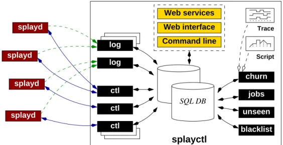
3.2 Architecture of the Splay controller (note that all components may be distributed on different machines). . . 33
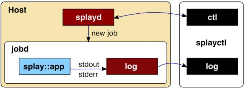
3.3 Instance of a new job on the host and connections with the controller. . 38
3.4 State machine of a Splay job on a host. . . . 40
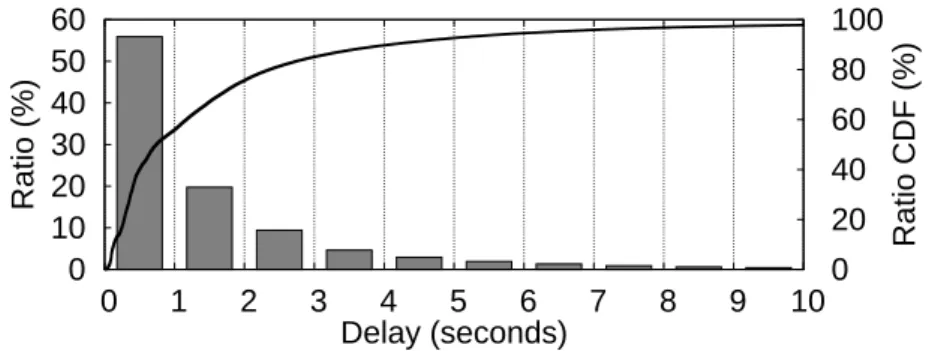
3.5 RTT between the controller and PlanetLab hosts over pre-established TCP connections, with a 20 KB payload. . . 41
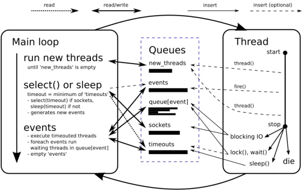
3.6 The scheduler . . . 47
3.7 Overview of the main Splay libraries. . . . 48
3.8 uRPC failures and error correction . . . 55
3.9 Example of a synthetic churn description. . . 65
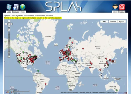
3.10 Geolocalized world visualization of splayds running on PlanetLab. . . . 76
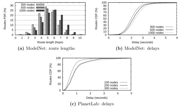
4.1 Performance results of Chord, deployed on a ModelNet cluster and on PlanetLab. . . 83
4.2 Comparison of delays of MIT Chord and Splay Chord on PlanetLab . 84
4.3 Comparisons of two implementations of Pastry: FreePastry and Pastry
for Splay. . . 85
4.4 Memory consumption and load evolution on a single node hosting several
instances of Pastry for Splay. . . 86
4.5 Pastry on PlanetLab, ModelNet, and both. . . 87
4.6 Using churn management to reproduce massive churn conditions for the
Splay Pastry implementation. . . 88
4.7 Study of the effect of churn on Pastry deployed on PlanetLab. Churn is
derived from the trace of the Overnet file sharing system and sped up for increasing volatility. . . 89
4.8 Deployment times of Pastry for Splay, as a function of (1) the number
of nodes requested and (2) the size of the superset of daemons used. . 90
4.9 Distribution of a 16 MB file using the BitTorrent Splay implementation. 91
4.10 File distribution using trees. . . 92 4.11 Cooperative Web cache: evolution of delays and cache hit ratios during
a 4 days period. . . 93
5.1 Discrete time simulation of redundant (“useless”) message delivery
ra-tios and coverage for push-based and pull-based epidemic diffusions in
a 10,000 node network. TTL is ∞ for the push-based simulation. . . . 101
5.2 Push-only: Coverage, number of complete disseminations and average
number of redundant (useless) messages received per peer, as a function of the TTL and Fanout. . . 102
5.3 Data structures of the Pulp algorithm. Note that messages come from
multiple sources (here A, B, and C) and each node sorts them based on the order it received them (which is generally different for each node). . 109
LIST OF FIGURES
5.4 Performance of the dissemination of 200 messages on a network of 1,001
nodes running on a cluster: individual cumulative delays, evaluation of the delay distribution, and evolution of the pull operations recall. . . . 112 5.5 Evolution of the reception latency distribution w.r.t. the coverage of the
initial push phase. . . 114 5.6 Evolution of the delays as seen by a set of 100 observers (static nodes)
under increasing churn rates. . . 115
5.7 Performance of the dissemination of 200 messages on PlanetLab. . . 117
5.8 Evolution of the pulling frequency w.r.t. new messages frequency. . . . 118
5.9 Reaction to a message burst with a one second minimal pulling frequency.120
5.10 Comparison of Pulp with an initial seeding phase (top), with no initial seeding phase hence relying only on push operations (middle) and a dissemination that uses only push to disseminate new messages and implicit pull proposals. . . 122 6.1 Usage of a companion search service. . . 131 6.2 Components & information flow. . . 133 6.3 Popularity distribution of queries in a dataset from AOL [102] follows a
typical Zip-like [16] distribution. . . 139 6.4 Principle of the delegation mechanism. . . 141 6.5 Impact of interest-based profiling. . . 147 6.6 Performance, single repository: max. possible load vs. repository size. . 148
Chapter
1
Introduction
There seems no plan because it is all plan. C. S. Lewis
1.1
Context
A distributed system refers to a set of computing entities collaborating for a task by communicating through a network. A client-server system is the simplest of distributed systems, but we consider in this thesis the more general case of a set of components that together create a virtual networked architecture, sharing various of their resources, in order to reach a common goal, in a collaborative manner.
Recently, we observe an unprecedented growth in the number and the scale and im-portance of deployed distributed systems. This is in great part due to the extreme increase in the amount of data that need to be stored and processed, a phenomenon which is often refereed to as Big Data. Traditional architectures such as client-server and SQL databases cannot handle such huge workloads appropriately.
Distributed systems provide effective solutions to face these new challenges in particular because of their support for scalability.
One can broadly characterize distributed systems as either loosely or tightly coupled systems. P2P (peer-to-peer) systems lie in the first category. In these systems, each user or host shares some resources to become a part and have access to the system. Here, the system could be designed to scale with the number of its users. The sec-ond category includes enterprise systems like clusters and server farms. Scalability is achieved by having the ability to transparently add resources to the existing set. Distributed architectures rarely provide the same functionalities and guarantees that were previously available with centralized systems (the main reason being that provid-ing such guarantees would ruin scalability and speed). To benefit from a distributed system, all the software stack has to be rethought.
It is very interesting to observe that, in parallel to the distributed systems challenge, the software industry also faces another challenge that shares some similarities: modern software has to scale with the number of processor cores available inside a single com-puter especially the concurrency problems. This seems to indicate the end of vertical scalability; which was obtained by replacing components with more powerful ones. In-stead, horizontal scalability is achieved by adding more components that will cooperate with the existing ones.
For several years, many papers have been published describing distributed algorithms for large-scale systems, for example, DHT (Distributed Hash Tables) in P2P networks [105, 121, 110, 134] . These papers often describe clever algorithms provided to the reader in pseudo-code format. During our studies of distributed systems, we encoun-tered on many occasions a huge problem related to these papers: the difficulty to validate their algorithms and reproduce performance results.
The gap between a theoretical pseudo-code and a working/testable implementation is very important. Many problems are encountered during this process: writing a working implementation (many real life problems, notably network delays and failures, are not in the pseudo-code), testing it on a simulator, deploying it on various testbeds, analyzing the results, and repeating this process until results.
Various languages, tools and testbeds help in that process. However, these components are far from providing a unified environment. Their specializations often limit them to a specific category of experiments. It is also difficult to combine them or to reuse some code when switching from one to another.
1.2 Contributions
1.2
Contributions
To address these limitations, we propose Splay, an infrastructure that simplifies the prototyping, development, deployment and evaluation of large-scale systems. Unlike existing tools, Splay covers the whole chain of distributed systems design and evalua-tion. It allows developers to specify distributed applications concisely using a platform-independent, lightweight and efficient language based on Lua [60].
Splay provides a secure and safe environment for executing and monitoring applica-tions, and allows for a simplified and unified usage of testbeds such as PlanetLab [1], ModelNet [127], networks of idle workstations, or personal computers.
Splay applications execute in a safe, sandboxed environment with controlled access to local resources (file system, network, memory) and can be instantiated on a large set of nodes with a single command. Splay supports multi-user resource reservation and selection, orchestrates the deployment and monitors the whole system. It is particularly easy with Splay to reproduce a given live experiment or to control several experiments at the same time.
An important component of Splay is its churn manager, which can reproduce the dynamics of a distributed system based on real traces or synthetic descriptions. This aspect is of primordial importance, as natural churn present in some testbeds such as PlanetLab is not reproducible, hence preventing a fair comparison of protocols under the very same conditions.
The system has been thoroughly evaluated along all its aspects: concision and facility of development, efficiency, scalability and features. Experiments convey Splay’s good properties and the ability of the system to help the practitioner or researcher through the whole distributed system design, implementation and evaluation chain, among which lie the following examples:
1. Testing overlays and other large-scale distributed systems, whose lifetime is spec-ified at runtime and usually short. In such a situation, one needs to get the results (i.e., logs) as fast and as easily as possible, and the deployment needs to be quick and reliable. A typical example is the analysis of the diffusion of a file using the BitTorrent protocol [42], where the experiment can be terminated once all nodes have finished downloading the file.
2. Running long-term applications, such as indexing services or DHTs. For instance, one may want to run in the long-term a DHT such as Pastry [110], this service being used by another application under test. A potential difficulty can stem
in the need to keep a fixed size set of nodes participating in the DHT. Splay facilities for node management make such a task easy.
3. Deploying short-term applications on a network of workstations as part of some course’s lab work. In such a situation, resource usage at the nodes must be controlled to avoid any impact on the workstations’ systems. Such a task would require much administration, especially with heterogeneous operating systems at testbeds’ nodes. Splay sandboxed execution environment in turn permits us to consider a broader range of testbeds for distributed systems evaluation.
The file transfer scenario is an emblematic example of our original intent when de-signing Splay: an overlay must be deployed for a task that is both occasional and relatively short. Without appropriate tools, the effort of constructing such an overlay is disproportionate compared to the task.
Applications are concise (e.g., less than 100 lines of code for a complete implementation of Chord [121]), platform-independent, lightweight and efficient. Splay applications
have access to a comprehensive set of libraries tailored for the development of dis-tributed protocols and overlays.
Splay has also been used as the development and evaluation framework for several research effort at the university of Neuchâtel and other universities worldwide. We
provide two representative examples of such from our work in chapters 5 and 6. The
experimental and validation efforts for both greatly benefited from the capabilities of the framework. They also illustrate that Splay can not only be used to write short prototypes, but also complex, long term running, applications.
Conciseness of implementation and ease of use of Splay allow it to be an educational tool of choice [108]. In a controlled environment (reliable network and nodes), it is possible to focus only on the algorithmic part of the problem. In more adverse conditions (natural or artificial, e.g., using churn system), Splay permits efficient error handling.
The name Splay is derived from “spontaneous overlay”, i.e., a distributed application or overlay network that is instantiated for a specific task, whose nodes are usually deployed simultaneously, and whose behavior (protocol) and lifetime are decided at instantiation time.
1.3 Organization of the Thesis
1.3
Organization of the Thesis
The thesis is organized as follows.
In Chapter 2(Context), we introduce distributed systems, their evolution, their main characteristics, how they are used by enterprises and why they are complex to design. In this context, we analyze more in depth some representative distributed systems and explain where and how could Splay have helped in their design. Finally, we give an overview of alternative technologies.
In Chapter3(The Splay Framework), we present all the fundamentals Splay
compo-nents and explain the main design choices. We provide details about the Lua language, the sandbox, how to write Splay applications, and how to do distributed experiments using Splay.
In Chapter 4(Evaluation of Splay), we perform a thorough evaluation of Splay per-formance and capabilities. We study the perper-formance of Splay by implementing real distributed systems and reproduce experiments that are commonly used in evaluations to compare it to other widely-used implementations. We demonstrate the usefulness and benefits of Splay rather than evaluate the distributed applications themselves. In order to demonstrate the benefits of distributed system research using Splay, the next chapters will present two systems that have been almost entirely implemented and evaluated using the Splay framework.
In Chapter5(PULP), we present Pulp, a generic and efficient push-pull dissemination protocol.
In Chapter 6(Collaborative Ranking and Profiling), we present a collaborative search companion that collect user searches to build profiling information over time and en-hance search experience by providing tailored results.
Chapter
2
Context
Every cloud engenders not a storm. William Shakespeare, “Henry VI”
2.1
The Advent of Distributed Systems
2.1.1
Mainframe computers
Mainframe computers are the oldest form of generalized computing. They first ap-peared in enterprises during the 1950s. For nearly three decades, they were the only form of computing available, long time before the apparition of personal computers. Today, they still play a major role in the world’s largest corporations that have done a major investment in their application and data.
The incredible success of mainframes is mostly related to remarkable compatibility that permits to combine application written “yesterday” with applications written more than fifty years ago.
Mainframe computers are an emblematic example of vertical scalability. While there are some distributed mechanisms available for modern mainframe, the essence of this architecture is to appear as a whole, indivisible system where each component can be replaced or updated transparently.
They way of achieving fault tolerance and availability is also emblematic: an important part of mainframe computer’s hardware and software is dedicated to failure detection of components and to have the ability to replace them without affecting normal operations (hot swap, spare components).
Despite their quality, these systems have some limitations. First, vertical scalability is always bounded to an upper limit defined by the highest end components a mainframe features and the maximum number of these. Second, the cost of a mainframe computer limits its adoption to businesses that can afford a very high cost per operation (banks, insurances, ...). Third, mainframes are mostly based on proprietary hardware, operat-ing system and applications. Interoperability is very limited, the customer is tightly coupled with a vendor, its architecture, its products, its support and its prices.
If mainframe computers still have a bright future, in corporations were storing and manipulating sensitive data in-house and with extreme reliability is a major require-ment, most companies are, however, interested in limiting their operational costs. For that purpose, they can deploy complementary systems doing data crunching at a more affordable, or on-demand, price.
2.1.2
Early years of Internet
Both centralized and distributed paradigms have been part of the computer networks since their early years. A good example of this symbiosis is the email system. The system itself is a distributed system where each server is responsible for a specific domain and acts as a relay when receiving emails for other domains. When users of a specific domain connect to the corresponding server to retrieve their emails, the server acts as a centralized (client-server) system.
In 1993, the World Wide Web (commonly known as the Web) become publicly avail-able. As the name suggests, the brilliant idea behind the Web is to easily connect different resources (pages from the same and different domains) together by using text links (hypertext [22]). Before this invention, exchanges between users were generally limited to people sharing the same interests (newsgroups, mailing lists, etc.), mostly in academic environments where Internet was already available.
The Web immediately permits enterprises to publish informations for everyone by just having a domain name and a server. The first Web browser (MOSAIC) provided a simple access to the Web and was at the origin of the public interest for the Internet.
2.1 The Advent of Distributed Systems
Until the mid-nineties, the main services provided by the Internet were static Web pages, emails, newsgroups, FTP (File Transfer Protocol) and IRC (Internet Relay Chat). The number of users was small (but growing fast) and home connections without broadband access: textual content was favored over images. Serving static Web pages was not very resource-consuming and was generally provided by a single server with just some extra hardware resources if needed (vertical scalability). The content being static, simple caching strategies were widely used by providers to reduce the traffic outside their network (using transparent or non transparent proxies).
2.1.3
Commercial Web Advent
The advent of commercial Internet websites (e-commerce) greatly changed the situ-ation. Due to their dynamic contents and to the fact that they must keep sessions containing data from the current visitor (shopping cart, etc.) and query external sys-tem (credit card, etc.), such syssys-tems needed much more resources for their operation. Henceforth, services provided over the Internet becoming more and more complex, vertical scalability was not enough anymore to support them.
To scale, different strategies were applied. The static content can be served very effi-ciently with almost no CPU requirements and benefits from the caching mechanisms of each ISPs (Internet Service Provider). The dynamic content can be split in indepen-dent parts being processed by different servers. Most dynamic content can also have a certain TTL (Time To Live) and thus can also be cached on the server side. The pages where then generated by multiple load-balanced servers, each of them asking shared data from a database server. In this scheme, the central database often becomes the bottleneck of the system.
At that time, there was the need to put the servers near the customers. The main problem was not the delay (theoretical delay is lower than 1/10th second between any two points on earth 1 ), but the bandwidth bottleneck between different regions of the globe 2. These various instances often need to be synchronized, at least partially, for example to have global user accounts. This leads to new difficulties and consistency problems.
1The distance between two antipodes is half of Earth’s circumference so ∼ 20000 km. If the speed
of light in vacuum is c, wave propagation in optical fibers is ∼ 2/3c, while in copper wire, the speed generally ranges from .59c to .77c. Obviously the physical links are not deployed in a straight line, many repeaters are on their route, and routing rules are not always optimal.
2.1.4
Google: Scaling with the Web
In 1998, Google, launched his new search engine. The success of Google was essentially based on their new page relevance algorithm, PageRank [31], but that was not their only innovation.
To parse the massive amount of data gathered by their Web crawlers, Google has been the first to build a server farm based on cheap commodity hardware; instead of spending a lot of money for highly priced servers, they opted to add more computers with cheaper hardware and manage fault tolerance at software level using their own distributed system.
Their system was able to do an efficient reverse indexation (word based index) and re-turn the most relevant results (sorted by PageRank) to a search automatically whereas previously there were only manually generated directories.
It is probably one of the first successes of a new kind of distributed infrastructure able to replace the classical super computer architecture. The most important feature was that Google’s architecture could easily scale by just adding new nodes as the number of Web pages was growing (approximately one billion pages at the end of the nineties).
2.1.5
Big Data Challenge
Since the beginning of the 21st century, we observe an exponential growth in data generated by the Web.
Globally, the involvement of users has evolved from spectators, only consuming data, to actors, generating much data by themselves.
It all began with the advent of blogs and CMS (Content Management Systems). The technical barrier for publication has been lowered by these user-friendly technologies and every user had finally the possibility to create his own website and add content to it.
More recently, social networks with AJAX (Asynchronous Javascript and XML) Web content, encourage this editorial practice. Everybody is asked to participate and to share more and more personal information. This evolution is commonly called Web 2.0.
2.2 Distributed Systems Characteristics
The quantity of data to process has grown faster than the computing power of each individual computer. Moreover, one cannot simply replace a set of computing resources by a new more powerful one. The availability of the services must be ensured, and scalability must be achieved by adding resources to the existing set.
With the Internet, any startup can expect to see the number of its users growing by several orders of magnitude within a few years. Such a change implies to particularly focus on the problematics of scaling. This is the best way to be able to keep a stable architecture while tolerating large computing variations without making a dispropor-tionate investments in resources that are not yet used. The availability of resources in the cloud is the perfect complement to this kind of architecture.
2.1.6
Mobile Computing
Mobile applications, and more generally wearable computing, have completely changed the way users interact with Internet. Before, a user has to explicitly consult a service to get data from it (pull). Today, mobile users are subscribed to services (having a mobile application is exactly as being subscribed to a service) and receive updates or notifications without requesting them (push). More than that, most users are unaware of the data they are publishing all the time: their location (GPS), usage statistics, etc. The amount of data is no more related to the number of users explicitly publishing something, but directly proportional to the number of users subscribed to a particular service.
A smartphone can also automatically upload/publish a picture a user has just taken on social networks or a remote storage while automatically adding metadata (GPS position, orientation, camera model, etc.) without any explicit user action. The amount and the exact type of information sent is unknown to most users.
2.2
Distributed Systems Characteristics
Distributed system are a set of computers (or more generally any device with a CPU, RAM, and, very often, persistent storage) connected to a network and globally managed via a dedicated software. Computers being part of the system are usually called nodes (sometimes peers when dealing with a decentralized system).
In recent years, many applications have been built upon the distributed computing model. Theses applications can potentially support a very high number of users con-nected to them or being an active part of the system itself (peer-to-peer). Very common examples of distributed systems are search engines who are using server farms to index the Web and to reply to queries, social websites like Twitter, Facebook and LinkedIn, dedicated applications like Skype and Zattoo or MMORPG (Massively Multiplayer Online Role-Playing Game) games like World of Warcraft.
Several types of distributed systems exist that vary according to the nature of the hardware and the type of software abstraction. We can typically classify them in two major categories: tightly coupled and loosely coupled systems. On tightly coupled systems, there is a global view of the system. The hardware is well known and stable. Computers are connected via a dedicated network and network availability is guaran-teed. Failures can be corrected by the owner of the system. Typical example of this structure are computer grids and server farms.
On the other end, loosely coupled system have more diversity: computers can use different operating systems, be in different locations and use different hardware (CPU power, amount of RAM, disk space, bandwidth).
P2P (peer-to-peer) systems are mainly characterized by the fact that each peer acts both as a client and a server. Most P2P systems use the computer resources of the participating users and can also be considered as highly dynamic or volatile systems be-cause the users (and their corresponding peers) stay online a limited and unpredictable amount of time, hampering making assumptions about their future availability. All these systems need to communicate using message passing and not via shared memory, like local applications do. Some implementations hide this communication model by presenting the distributed system as a single system. A common example of this usage are distributed operating systems that appear to the users as a single computer [3] [4].
Other commonly used abstractions are RPCs (Remote Procedure Call) and distributed file systems. The first one permits to call functions of a remote application instance almost as easily as a local function call. The main difference is that the function may fail due to an external condition (network, remote node shutdown, etc.) and this particular situation must be detected. Distributed file systems provide a global common storage accessible by all the nodes. The problems in that case are related to synchronization and efficiency.
2.2 Distributed Systems Characteristics
Enterprise distributed systems are an important class of LSDS (Large Scale Distributed Systems) with a large amount of nodes, where new nodes can be added when there is a need to scale. This is the opposite of a static distributed system like a cluster of computers or a grid where the amount of nodes is mostly fixed (although some cluster infrastructure support addition of hardware nodes on the fly).
2.2.1
P2P Systems
P2P systems are a specific form of distributed architectures where nodes act both as consumers and suppliers of resources. Users wanting to benefit from specific material provided by the P2P network need to run their own node to access them.
In a P2P network, tasks such as nodes organization, indexation or searching for files are shared amongst all the participating nodes. This requires each node to make available part of its computing resources (processing power, disk storage, network bandwidth) to other nodes. Finally, some user may provide some unique material to be shared in the network.
The hardware problems being delegated to the participants, the system as a whole cannot make any assumptions about the availability of nodes.
Some of the main challenges of P2P applications are:
Cumulative/recursive delays. Many nodes may be involved (sometimes recursively) to answer a request.
Persistence. If all nodes containing a unique piece of data disappear, this data will not be available until at least one of these nodes comes back.
Replication. To ensure persistence, data need to be replicated.
Privacy. Private data can be distributed (stored on many nodes) but only some of the nodes with the proper credentials, must be able to read it.
Slow nodes. Many algorithms involving a set of nodes (especially in a recursive fash-ion) perform badly with slow or unresponsive nodes.
Ill-behaved peers. Peers that do not play by the rules (selfish behavior, data cor-ruption, etc.), shall not tamper the service availability.
NAT traversal. The lack of public IPv4 addresses has spread the usage of NAT routers in enterprise and family networks. Without additional routing rules, a server behind a NAT is not directly accessible. Several solutions exist to leverage this [70, 109], but they require complex mechanisms and may not deal with all possible NAT couplings.
Asymmetric bandwidth. Most broadband connections have different upload and download speed (download being favored). The asymmetry makes it difficult for a balanced sharing of resources.
Bootstrap. To access a P2P network it is necessary to know a node already partici-pating (or someone that can give a list of participartici-pating nodes).
Most of these problems result from the lack of any guarantees on the participants and the uniformity of P2P networks.
To overcome these difficulties, hybrid systems are often used:
Permanent super nodes. Super nodes are elected nodes that get more responsibil-ities in the network. It is a common mechanism in P2P systems to improve the stability and efficiency of the network. Instead of relying on elected nodes, highly reliable permanent super nodes can be directly inserted by the network owners. Super nodes help the system to behave better, but they are not necessary for the network to operate.
Indexes/Trackers. Additional servers are used to keep track of participating nodes and index what they have. The exchanges between the nodes still use pure P2P. The external servers are not active peers of the system and use different software. The network cannot work without them.
2.2.2
Cloud Computing
Cloud computing provides the ability to access computing resources/applications, on demand via Internet. It is not a technological evolution (every involved technologies already existed before being deployed in the cloud) but an economical one.
Cloud computing offerings are generally divided into three categories:
IaaS (Infrastructure as a Service) Provides virtualized resources, in the form of virtualized computers with a specific amount of CPU, memory, disk and band-width.
2.2 Distributed Systems Characteristics
PaaS (Platform as a Service) Provides an execution platform for applications, of-ten providing fail-over mechanisms and load balancing.
SaaS (Software as a Service) Applications available via Internet. The user doesn’t manage any part of the application, he just pays for access to it.
With cloud computing, even a very small company can launch a service without in-vesting capital in heavy equipment. There are also economies of scale and ecological considerations in cloud computing. Companies share the same resources instead of investing in static resources that would be idle a significant part of the time (idle re-sources consume less, but still consume something) by using the same rere-sources, but at different times (different peak hours in the same day depending of the time zone or different days in a year).
2.2.3
The CAP Theorem
Distributed systems are prone to issues that do not exist in monolithic systems: failure of a number of nodes, messages loss (loss of network connectivity, saturated bandwidth, etc.).
In this context, it is important to define more precisely which properties can be achieved and under what conditions.
The initial “CAP” conjecture was made by Eric A. Brewer in an invited talk [30] at
PODC 2000. It was proven later by Gilbert and Lynch [57] as the CAP theorem.
The CAP theorem states that it is impossible for a distributed system to simultaneously provide all three guarantees:
C (Consistency) All nodes see the same data at the same time. A (Availability) Every request will receive a response.
P (Partition tolerance) The system will continue to operate, despite partial failures and message loss.
As described, a CP system appears to be an unavailable, partition tolerant and con-sistent system ! The misunderstanding resides in the meaning of each letter. A non-C system will have only casual consistency (consistency is not a goal). In a CP system, availability is only sacrificed in case of network partition.
Research in DBMS (DataBase Management Systems) has (mostly) focused on provid-ing ACID guarantees:
A (Atomicity) All operations in a transaction will be completed or none will. C (Consistency) The database will be in a valid state before and after each
trans-action.
I (Isolation) Each transaction will behave as if it was the unique operation on the database at the same moment.
D (Durability) The result of a complete transaction is stored permanently.
To provide better availability, graceful degradation and performance, "C" and "I" must be sacrificed. Brewer proposes the BASE properties (Basically Available, Soft-state, Eventual consistency) to replace the ACID ones. In these new databases, it is sufficient to be in an eventually consistent state rather than being consistent after each transaction.
Developing software using fault-tolerant BASE is harder than relying on ACID sys-tems, but necessary to scale up. There is a continuum between ACID and BASE: one can choose how close one wants to be to either end depending of the application requirements.
2.3
Distributed System Design
Developing large-scale distributed applications is a highly complex, time-consuming and error-prone task.
One of the main difficulties stems from the lack of appropriate tool sets for quickly prototyping, deploying and evaluating algorithms in real conditions, when facing un-predictable communication and failure patterns.
Nonetheless, evaluation of distributed systems over real testbeds is highly desirable, as it is quite common to discover discrepancies between the expected behavior of an application as modeled or simulated and its actual behavior when deployed in a live network.
2.3 Distributed System Design
While there exist a number of experimental testbeds to address this demand (e.g., PlanetLab [1], ModelNet [127], or Emulab [131]), they are unfortunately not used as systematically as they should. Indeed, our firsthand experience has convinced us that it is far from straightforward to develop, deploy, execute and monitor applications for them and the learning curve is usually steep.
Technical difficulties are even higher when one wants to deploy an application on sev-eral testbeds (deployment scripts written for one testbed may not be directly reusable for another, e.g., between PlanetLab and ModelNet). As a side effect of these dif-ficulties, the performance of an application can be greatly impacted by the technical quality of its implementation and the skills of the person who deploys it, overshadowing features of the underlying algorithms and making comparisons potentially unsound or irrelevant. More dramatically, the complexity of using existing testbeds discourages re-searchers, teachers, or more generally systems practitioners from fully exploiting these technologies.
Many other distributed deployment platforms could be leveraged for activities related to distributed system design and evaluation (research, teaching, monitoring, etc.). Ex-amples of such platforms are networks of idle workstations in universities, research facilities and companies, networks of personal PCs whose users donate some idle CPU time or ubiquitous hardware like smart phones.
As any PlanetLab user can testify, it is a highly technical task to develop, deploy, execute and monitor applications for such complex testbeds. Technical difficulties are even much higher when one wants to develop for and deploy and execute applications onto several testbeds. The lack of adequate tools for these tasks increase significantly the amount of work to use them efficiently.
These various factors outline the need for novel development-deployment systems that would straightforwardly exploit existing testbeds and bridge the gap between algorith-mic specifications and live systems.
For researchers, such a system would significantly shorten the delay experienced when moving from simulation to evaluation of large-scale distributed systems (“time-to-paper” gap). Teachers would use it to focus their lab work on the core of distributed programming—algorithms and protocols—and let students experience distributed sys-tems implementation in real settings with little effort. Practitioners could easily vali-date their applications in the most adverse conditions.
There are already several systems to ease the development or deployment process of dis-tributed applications. Tools like Mace [72] or P2 [89] assist the developer by generating code from a high-level description, but do not provide any facility for its deployment or
evaluation. Tools such as Plush [18] or Weevil [130] help for the deployment process, but are restricted to situations where the user has control over the nodes composing the testbed (i.e., the ability to run programs remotely using ssh or similar).
They are not meant for testbeds where only limited access rights are available, and/or where the owner of the nodes wants to strictly restrict resources usages, or wants to prevent any erroneous or malicious application harming the system.
2.4
LSDS in Industry
2.4.1
Introduction
To face the Big Data Challenge, LSDS have become a fundamental part of the enter-prises computing ecosystem.
In order to present the LSDS goals and problems, we will analyse four typical LSDS building blocks, how they stack together and, later, explain where Splay could have been useful during their prototyping phase.
Considering Google has pioneered the domain1, we will focus on their papers describing four of their production-ready LSDS implementations:
GFS (Google File System) A DFS (Distributed File System). MapReduce A framework for parallel computation.
Chubby A distributed lock/file/DNS service. BigTable A NOSQL (Not Only SQL) database.
We will also mention The Hadoop Project that provides open source software to build scalable and data-intensive distributed applications. Initially, it was mainly a Java implementation of architectures corresponding to those described in the MapReduce and GFS papers. Today, it also embraces many related distributed system projects that are built upon this underlying infrastructure (Cassandra, HBase, ZooKeeper, etc.).
1 Their success is also often associated with the fact they were able to build distributed systems
2.4 LSDS in Industry
Figure 2.1 – GFS Architecture [Wikipedia, CC0 license]
2.4.2
GFS
GFS is a distributed file system. It was first described in [56]. HDFS [29] (Hadoop Distributed FS) is the corresponding Hadoop implementation.
It was developed with the following goals and assumptions:
• Provide redundant storage of large amounts of data using inexpensive computers (high failure rate).
• Optimize datacenter bandwidth by providing location aware replication. • Millions of huge files (> 100Mo, typically several GB).
• Write once (mostly), streaming reads.
The GFS cluster architecture consists of two types of nodes: one master node and a large number of chunk servers (see Figure 2.1). Chunks are multiple parts of a single file.
For efficiency reasons, each chunk has a fixed size of 64Mo and is assigned a unique 64-bit identifier by a master node at the time of its creation. The master node keeps the mapping between files and the constituent chunks and coordinates operations on files: it stores their metadata and select the chunk servers involved in the successive read or write operations. Finally, a GFS client library will permit to directly communicate with the master and the chunk servers. Basically, the chunk servers only know how to store, serve and delete chunks, without having any global view.
The master node is the interface to all operations between the clients and the physical storage (the chunk servers). As a central point of coordination, it will limit the scala-bility of the cluster. For that reason, the master involvement in file operations must be kept as low as possible. The data exchanges are done directly between chunk servers (chunk replications) and between the GFS clients and the chunk servers.
When the master receives a command to store a new file, it first creates an entry for the metadata information received from the GFS client: namespace, filename, type, size, times, etc. Then, the master will reply to the GFS client a selection of the less loaded chunk servers that will store the chunks. When each chunk is safely stored, the master will update the file metadata with the locations of the chunks and their checksums. After a client request for a file, the master, knowing where chunks are stored, will return the list of chunks with their corresponding chunk servers (the master will reply an incomplete list of chunk servers for a given chunk, again it selects the most appropriate chunk servers depending of their load).
The master also organizes the replication of chunks. Three copies are the minimum (they ensure safety and availability of the data) but depending of the level of requests for a particular chunk, the master will dynamically increase the number of replicas to improve load balancing (and will recover some space when the number of requests decrease). The master permanently monitors chunk servers for their availability and trigger the replication process in case the replication degree of some chunks has fallen beneath a threshold.
In order to have a bandwidth effective replication, GFS is location aware (it knows on which switch the chunk server is connected, other chunk servers on the same switch are considered a part of the same rack. In a typical setup, the data are duplicated three times: two times in a close proximity (same rack, local switch) and once more remotely (in another rack). The bandwidth inside the same rack is probably higher, and in all cases cheaper.
2.4 LSDS in Industry
When a file is deleted, the master will launch a garbage collection process that ensures that the corresponding chunks will be deleted.
To have the master be fault tolerant, several shadow masters run in parallel of the actually used master. They replicate all its operations using a replication log. If the master goes down, a new master is automatically elected and replaces the failed one. As previously stated, the role of the chunk servers is much simpler: they are mainly used to store and serve chunks when requested. Additionally they also checksum the chunks when writing them to ensure correctness. The limited size of the chunks ensures a good repartition between chunk servers and also improves memory usage (small chunks permit to better fill the available memory of each server).
The application communicates with the distributed file system using the GFS client. The GFS client does not act as a simple library, but is an active component that first communicates with the master using RPC, then with the chunk servers for the data stream. The GFS client also caches the master’s files metadata to offload it as much as possible.
Some of the major implementation challenges in GFS include:
• Effective replication of chunks.
• Master recovery: replicated logs of operation, shadow master with replica. • File mutations (write/append):
· Replica must be synchronized.
· Master involvement must be minimized.
• Load balancing read/write operations for chunk servers.
A typical GFS cluster involves hundred of nodes running in a well-defined environment: all chunk servers are very similar (CPU, storage, RAM) and the bandwidth between nodes is known.
2.4.3
MapReduce
MapReduce is a framework for parallel computations. It was first described in [44]. The MapReduce algorithm is directly inspired by two common operations used in functional programming to work with lists:
Map Applies a function to all elements of a list and return a new list.
Reduce High-order function, also called a fold function in functional programming, that recursively analyzes a data structure and recombines it, returning a result (if the result is a list, it can be given as an input to another map or reduce function).
The MapReduce framework provides a parallel execution environment for every prob-lem expressed in the form of a map and a reduce functions.
The initial data domain is the raw input. It is then split into chunks represented by pairs (k1, v1). If the input is a file system, k1 can be the filename and v1 the content. If the input is a video stream, v1 can be the content of the chunks while k1 being the hash of the respective chunks. The (k1, v1) pairs are then dispatched to the mappers. Each mapper will then compute Map(k1, v1) → list(k2, v2). (k2, v2) is a new data domain were we search a solution for each k2. k2 will also be used to select the reducer node (the node that will apply the reduce function) typically using a classical k2 mod number_of_mappers dispatching (it is fundamental that each identical k2 goes to the same reducer).
The reducer node for k2 will receive all the corresponding v2. It can then perform the reduction Reduce(k2, list(v2)) → k2_solution.
MapReduce is a very smart way to parallelize operations on massive data inputs. But, as always, these distributed operations can be more or less effective depending of the quality of the architecture’s implementation.
A very challenging part, in this case, is to provide data to the mappers and reducers. To effectively compute Map(k1, v1) and Reduce(k2, list(v2)), the nodes have to get the corresponding data locally.
The data chunks (v1 ) should not be too small or too big: small enough to fit into the mapper’s memory (avoiding swapping) and to provide a good load balanced distribution between all mappers, big enough to not add unnecessary overhead.
2.4 LSDS in Industry
The reducers need to wait for all the v2 values associated to one k2 (the mapping process must be finished) before doing the reduction (generally, v2 values are also ordered by an additional application specific function before being reduced). A badly balanced mapping step would delay the beginning of reductions.
2.4.4
Chubby
Chubby [33] is a lock service for loosely-coupled distributed systems. It provides coarse-grained locking as well as a reliable distributed file system. The design emphasis is on availability and reliability (through replication), as opposed to high performance. Chubby is now used in key parts of the Google’s infrastructure, including GFS, MapRe-duce and BigTable. Google uses Chubby for distributed coordination and also to store small amounts of metadata.
A typical Chubby cell consists of five replicas (up to two servers can be down), each running on a dedicated machine. At any time, one of this replica is considered to be the master. When a Chubby client contacts one of the replica not being the master, the replica replies with the master’s network address. If the master fails, a new master is automatically elected. The asynchronous consensus is solved by the Paxos [77] [76] protocol.
Chubby exposes its data using paths similar to the UNIX file system. Access to files is filtered using ACLs (also stored in the file system) and a process can request a lock before doing operations on a file. The locks are advisory and not mandatory: the lock mechanism is only applied between processes requesting a lock; non-locking access to a file is always possible.
Chubby uses the Paxos protocol to synchronize a log file describing all successive op-erations in the database. Replicas agree on the execution order of client requests using the consensus algorithm. When the consensus is reached, the new value is append to the log file. The value is then written in the local database to be used by the Chubby APIs.
As stressed in [38], implementing theoretically well studied protocols such as Paxos is much harder than expected. Authors emphasize the difference between a pseudo code algorithm and a production-ready system where many features and optimization must be done before being usable.
In the purpose of validating their implementations, Google engineers have developed a lot of stress tests, error injections, etc. Some of these failure/recovery mechanisms were very dependent on the underlying OS (thread scheduling, disk synchronization, etc.).
Hadoop’s “equivalent” for Chubby is ZooKeeper [59]. However, the design and
fea-tures of ZooKeeper slightly differ from the ones of Chubby (e.g., ZooKeeper supports notifications and a tree structure for storing shared metadata). ZooKeeper does not use Paxos, but Zab [64, 65], , which provides linearizability through primary-backup replication instead of serializability in order to improve read scalability.
2.4.5
BigTable
BigTable [39] is a NOSQL column-oriented database (values for a column are stored
contiguously) designed to scale to a very large size: thousands of server storing petabytes of data with high performance, scalability and reliability. Google uses BigTable to store data for more than sixty of their products. The corresponding Hadoop implementation is HBase.
NOSQL databases have been created to deal with huge quantities of data that the traditional RDBMS (Relational DataBase Management System) solutions could not cope with.
NOSQL is a class of DBMS that does not follow the widely used relational model:
• The query language is not SQL. • It may not provide ACID guarantees.
• The architecture is distributed and fault tolerant.
A BigTable is a sparse, distributed, persistent, multi-dimensional, sorted map.
Sparse. Few entries are defined compared to the total index space.
Distributed. The implementation provides fault-tolerance and availability.
Multi-dimensional. The map values are indexed by (row, column, time). Time acts as a revision control system.
2.4 LSDS in Industry
Rows keys (arbitrary string up to 64k) are lexically indexed and distributed across servers. Read/write of a row is atomic for all its content. A range of rows, called a tablet, is the unit of distribution and load balancing. Each table server contains many tablets, so all the operations concerning a row can be done locally on the server that owns it. The tablet size is limited to approximatively 200MB; when it grows, the tablet is split.
Data items are often primarily indexed by their URLs (in reverse domain order). Dif-ferent URLs from the same domain will be lexically close, thus insuring that pages of a domain are stored near each other (in the same tablet and/or the same server). As each column needs to be part of a column family, the key will be in the form: ‘family:qualifier’. The families serve as access control and also as compression groups. The content of a family generally being of a same type, compression gains are better (and the chosen compression algorithm can be set for a particular family type). The timestamp index (in microseconds) serves as a version control. By default, using only row and column indexes, the last content is returned (or written using the actual time). The timestamp is also used by the garbage collector to keep the latest n revisions or keep the revisions where their age is smaller than a limit.
The tablets are stored on GFS using the SSTable (Sorted String Table) file format. The SSTables are immutable, contain a number of arbitrary sorted key-value pairs inside and an index. An SSTable completely or partially (just the index) mapped in memory is called a MemTable. Writes goes directly in the MemTable, reads check first the MemTable then the SSTable indexes. Periodically the MemTable is flushed on disk as an SSTable. Periodically the SSTable are merged.
A BigTable master is responsible for garbage collecting unused SSTables, monitoring the availability of tablet servers, load balancing the tablets between servers and orga-nizing the recovery of tablets when a server is failed (the master will assign its tablets to new servers and prepare the recovery process). Multiple master servers are available, but only one is active, Chubby is used to obtain the lease.
To find which server manage a specific table entry, a two level meta-tables indexes the locations of tablets. The root meta-table location is also stored in Chubby.
2.4.6
Splay Applicability
In the following sections, we emphasize the role that Splay could have had in the design of the previously seen distributed systems. Compared to most other tools, Splay permits researchers to evaluate prototype applications on conditions very similar to the final ones (e.g., using similar hardware and network architecture). Even if Splay will not help for the final tuning (or operating system specific tuning), its performances permit us in most cases to have implementation that can handle a load comparable to that of the final application and save a lot of time during the conception phase until the stabilization of the protocols.
2.4.6.1 GFS
To evaluate a similar environment in Splay we could have used a local cluster of com-puters. Each computer would act as a rack containing the chunk servers (represented
by a splayd 1 instance running on the computer). The chunk servers running on the
same computer will have access to a very high bandwidth that can be limited by an external tool like trickle because Splay currently does not include integrated band-width shaping. The connectivity between the nodes of the cluster will represent the connectivity between the racks in the GFS datacenter.
The master node (and shadow masters) can be placed on a dedicated computer as if they were not on the same rack as chunk servers.
Splay makes it very easy to exchange control commands between the nodes using the integrated RPC mechanism. For data transfers, plain TCP connections can be used. Splay provides a file system abstraction to store files (in this case, chunks) on the underlying file system with a very low overhead. The available disk space can be split between all the splayd running on the same computer. To checksum each 64KB blocks of chunks, Splay provides the MD5 or SHA mechanisms directly from OpenSSL C libraries.
2.4.6.2 MapReduce
A production-ready MapReduce is tightly coupled with GFS. Even if Splay permits us to deploy multiple applications (one for GFS and one for MapReduce) at the same time and make them communicates, we probably would be too far from the real system to provide a realistic implementation at a performance and scalability point of view.
1
2.4 LSDS in Industry
In that case, at least two alternative approaches could be considered:
1. Bundle the production ready GFS client with splayd: that way we could test the MapReduce application on top of a realistic layer.
2. Completely skip the DFS part to concentrate on a more unified MapReduce-only approach.
The unified approach, in this case, consists at sending the data blocks ((k1, v1) and (k2, v2)) directly between the nodes (not using a DFS at all). Each node will have its own role (input, map, reduce, sort) and will queue the job on its local file system before being processed.
As splayd internally uses only coroutines and no threads, it will at most use only one CPU core. When using Splay for computational tests, one will run (at least) as many splayds as cores present in the physical machine. Map and reduce being functions that can possibly use a parallel implementation, the Splay approximation will be to run multiple independent processes instead of a parallelized one.
In this scenario, we could have each deployment validate one specific algorithm, but we can certainly do it better using the fact that Splay, using the Lua language, can directly pass code between nodes. Therefore a client could use the MapReduce test network for directly sending (destination, data, map function, reduce function, sort function) to an input node and get the result back (the Lua functions being transmitted between nodes along (k1, v1) and (k2, v2), the overhead will often be negligible).
2.4.6.3 Chubby
While Splay cannot replace the testing of a production-ready implementation, we believe that it is an excellent candidate for implementing and testing algorithms like Paxos, which act as fundamental primitives for the upper layer (database and APIs). Initially, much time is spent to just transform the pseudo code into a working protocol, before adding the needed features and optimizations. Using Splay RPCs will probably highly reduce the implementation time while producing a fully testable result.
Splay churn module and RPC dropping mechanisms can be very helpful to test fail-ures and recovery in consensus protocols. In order to be compatible with the Paxos assumption on a persistent storage we would have to add support for Splay to preserve the node disk storage between shutdown and restart.
2.5
Related Work
Splay shares similarities with a large body of work in the area of concurrent and distributed systems. We only present systems that are closely related to our approach.
2.5.1
Development tools
On the one hand, a set of new languages and libraries have been proposed to ease and speed up the development process of distributed applications.
Mace [72] is a toolkit that provides a wide set of tools and libraries to develop dis-tributed applications using an event-driven approach. Mace defines a grammar to specify finite state machines, which are then compiled to C++ code, implementing the event loop, timers, state transitions, and message handling. The generated code is platform-dependent: this can prove to be a constraint in heterogeneous environments. Mace focuses on application development and provides good performance results, but it does not provide any built-in facility for deploying or observing the generated dis-tributed application.
P2 [89] uses a declarative logic language named OverLog to express overlays in a
compact form by specifying data flows between nodes, using logical rules. While the resulting overlay descriptions are very succinct, specifications in P2 are not natural to most network programmers (programs are largely composed of table declaration statements and rules) and produce applications that are not very efficient. Similarly to Mace, P2 does not provide any support for deploying or monitoring applications: the user has to write his/her own scripts and tools.
Other domain-specific languages have been proposed for distributed systems
develop-ment. In RTAG [19], protocols are specified as a context-free grammar. Incoming
messages trigger reduction of the rules, which express the sequence of events allowed by the protocol. Morpheus [15] and Prolac [74] target network protocols development. All these systems share the goal of Splay to provide easily readable yet efficient imple-mentations, but are restricted to developing low-level network protocols, while Splay targets a broader range of distributed systems.
![Figure 2.1 – GFS Architecture [Wikipedia, CC0 license]](https://thumb-eu.123doks.com/thumbv2/123doknet/15019496.682646/43.892.109.760.214.597/figure-gfs-architecture-wikipedia-cc-license.webp)