Publisher’s version / Version de l'éditeur:
Vous avez des questions? Nous pouvons vous aider. Pour communiquer directement avec un auteur, consultez la
première page de la revue dans laquelle son article a été publié afin de trouver ses coordonnées. Si vous n’arrivez pas à les repérer, communiquez avec nous à PublicationsArchive-ArchivesPublications@nrc-cnrc.gc.ca.
Questions? Contact the NRC Publications Archive team at
PublicationsArchive-ArchivesPublications@nrc-cnrc.gc.ca. If you wish to email the authors directly, please see the first page of the publication for their contact information.
https://publications-cnrc.canada.ca/fra/droits
L’accès à ce site Web et l’utilisation de son contenu sont assujettis aux conditions présentées dans le site LISEZ CES CONDITIONS ATTENTIVEMENT AVANT D’UTILISER CE SITE WEB.
Report (National Research Council of Canada. Division of Building Research), 1955-07-01
READ THESE TERMS AND CONDITIONS CAREFULLY BEFORE USING THIS WEBSITE.
https://nrc-publications.canada.ca/eng/copyright
NRC Publications Archive Record / Notice des Archives des publications du CNRC :
https://nrc-publications.canada.ca/eng/view/object/?id=f7e3df68-58f4-415a-8072-88872e022dcd https://publications-cnrc.canada.ca/fra/voir/objet/?id=f7e3df68-58f4-415a-8072-88872e022dcd
NRC Publications Archive
Archives des publications du CNRC
For the publisher’s version, please access the DOI link below./ Pour consulter la version de l’éditeur, utilisez le lien DOI ci-dessous.
https://doi.org/10.4224/20386799
Access and use of this website and the material on it are subject to the Terms and Conditions set forth at
Comparison of Combustibility Test Procedures
CANADA
DIVISION OF BUILDING RESEARCH
COMPARISON OF COrffiUSTIBILITY TEST PROCEDURES by K. Sumi Report No.
43
of theDivision of Building Research
Ottawa July
1955
Pre race
This report describes the results from work undertaken by the Fire Research Section or the Division of Building Research to assist the Sub-Committee of the Canadian Standards Association charged with the preparation or a new combustibility test specirication for
Canada. The results or further studies, together with recommendations on testing procedures and apparatus will be presented in subsequent reports.
The author,
Mr.
Kik Sumi, left rorGreat Britain to begin a year study in fire research before the report could be completed. Credit is due, therefore, to his colleagues in the Fire Research Section, particularly セセN G. Williams-Leir and !1r. J. R. Jutras, who have spent much time on revisions t9 the first draft report prepared by
Mr.
Sumi.No Bo Hutcheon, Assistant Director.
ottawa
by
K. Sum!
The words "incombustible" (or noncombustible) and "combustible" are used in building codes, specifioations, and other regulations often without being adequately
defined. As used in such documents, an incombustible material means a material which will not burn under
conditions of exposure which the user of the word has in mind. It will not necessarily have the same meaning to others unless those conditions are specified. This is often true in bUilding code work in classifying
combustibility of a material containing minor amounts of combustible constituents in an otherwise incombustible material. Thus there seems to be need for a suitable
performance test with reference to a well defined testing procedure.
Since the withdrawal of Specification A54-l940 by the Canadian Standards Association a new specification has been needed. The work which this report describes was done at the instigation and for the gUidance of the
sub-committee charged with preparing the part of the new specification dealing with combustibility tests.
The purpose of this investigation was to compare the merits of the combustibility test procedure of the British Standards Institution with certain procedures suggested by the writer using a furnace essentially the same as the one described in a previous report (2).
Seven different building materials were tested. The procedure used with the apparatus of the American Society for Testing Materials was based largely on the decisions made by Sub-Committee V of ASTM Committee E-5 on Fire Tests of Building Materials and Construction when the investigation reported herein was initiated. The procedure used with the British furnace was in accordance with "Combustibility Test of セゥXNエ・イゥ。ャウB described in
British Standard 476:1953, "Fire Tests on Building Materials and structures" (1).
PREVIOUS WORK
The need for a suitable performance test for classifying combustibility of bUilding materials led the British Standards Institution to the adoption of the
"Incombustibility Test of lJfa.terials" described in British Standard 476-1932 (3). In this method a specimen is
2
suspended in an electrically heated tubular furnace and heated gradually for
Ira
hours to a temperature of13820F. (7500
c) ,
while observations are made of flaming or glow of the specimen.Investigations made by N. P. Setchkin and S. H. Ingberg of the U.S. National Bureau of Standards and reported to the American Society for Testing
Materials in 1945 (4) led to a number of conclusions, one of which was that the British incombustibility test could be improved b
6
setting the furnace at the finaltemperature of 1382 F. before inserting the specimen instead of raising the temperature gradually with the specimen in. This makes a more severe test.
In February 1952 the author was co-author of a report "ASTM Combustibility Tests" (2). The work
reported was the Fire Research Section's contribution to a program of tests in co-operation with other
laboratories. This program was organized by the
American Society for Testing イセエ・イゥ。ャウ[ its purpose was to assist in the studies undertaken by Sub-Committee V of ASTM Committee E-5 on the development of a standard
method of test for defining the incombustibility of building materials. Samples of forty-seven different bUilding
materials were distributed to the Fire Research Section and four American laboratories. The furnace used was patterned on the British apparatus described in B.S. 476: 1932 which in turn is apparently related to the. 1915 design of Prince (5). Provision was made for a regulated flow of air through the furnace. After the temperature in the
furnace was stabilized at 1382op o with air-flow of 200 cof.m., the specimen was inserted. The test was continued for 15 minutes unless the specimen ignited or disintegrated during that interval of time.
In 1953, the British Standards Institution issued a revision of the British Standard (1). In this the
above-mentioned conclusion of Setchkin and Ingberg seems to have been adopted, and the procedure as regards setting the furnace temperature is similar to theirs.
EXPERIMENTAL DETAILS
n1e experimental details apply to tests carried out in both furnaces unless otherwise stated.
Apparatus
ASTM furnaceu- A furnace similar to the one used f'or the "ASTM CombustTbi1ity Tests" but with minor
fused-alumina refractory tube of 3-inch inside diameter and l/8-inch wall thickness was used as the inner wall of the furnace. A 4-inch inside diameter tube of the same material of 3/8-inch wall thickness,with spiral grooves for winding the heating
element was arranged coaxially so that the annular space between the tubes would serve as a preheater fqr the incoming air.
Nickel-chrome -vJire of l8-gauge Brown and Sharpe with a total resistance of 15.5 ohms was used as the heating element. This wire was embedded in a refractory cement. The cover was made in two semi-circular parts with a circular opening 1 sq. in. in area at the centre. The furnace had an outside diameter of 10 inches o other details are as shown in Fig. 2.
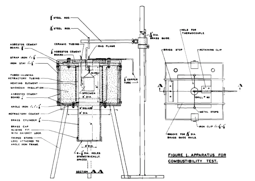
BSI Furnace. - The second ヲオイセ。」・ constructed was made as alike as possible in all relevant details to that desc.ribed in B.S. AセWVZQYUS (1). Like the latter, it had an observation window in the lower brass cylinder though this has been omitted from Fig. 1 as no use was made of it. A fused-alumina refractory tube of 3-inch inside diameter and 3/8-inch wall thickness was used as the inner wall of the furnace. Nickel-chrome l'ITire of l8-gauge B &; S with a total resistance of ャャセNッ ohms was used as the heating element.
Each furnace was heated by passing an electric current through the heating wires. A variable auto-transformer connected to the 220-volt mains was used for regulating the temperature in the furnace. A pilot gas flame, 518 to 778 inch in height, fed through a 0.04-inch port in the wall of a copper tube,
1/8
inch inside diameter, was located ゥュセ・、ゥ。エ・ャケ above the furnace opening.
Temnerature Distribution+
In order to increase m10wledge about the experimental conditions of the tests, the temperature profile of each furnace was determined, temperatures being measured at points one inch apart along the axis of the refractory tubes in the absence of a test specimeno In the case of the ASTM furnace, this was done with zero and 00 5 cof.mo air-flow. Results from these
determina-tions are shown graphically in Fig. 19.
Since the operating temperature of l382°F. is based, in the ASTM furnace, on a thermocouple at a point
i
inch below the specimen and, in the ESI furnace, on a thermocouple at the level of the centre of the specimen, it can be readily seen from Fig. 19 that the thermal environment of the specimen is more rigorous when using the ASTM furnace, particularly so under zero air-flow conditions. For example, comparing the ESI conditions' with the ASTM furnace without air-flow, the specimen base is 90°F cooler in the former and the specimen top 108°F cooler.4
Thermocouples
The thermocouples were made of 22 B
&
S gauge chromel-alumel wires welded at the junction. A multi-channel, self-balancing, recording potentiometer was used in conjunction with the thermocouples for measuring the tempera ture soa) ASTM furnace.- Four thermocouples were used: Tl on the heating element; T2 about t-inch below the bottom of the specimen; T3 on the surface of one of the sides of the specimen; and Th in the centre of the specimen. The
latter was omitted in tests on cinder block. b) BSI furnace.- The furnace temperature was
taken as that of a thermocouple situated at the level of the centre of the specimen and 3/8-inch from the internal wall of the heating tube.
Air-.flow
For the ASTM furnace the air was supplied from the laboratory compressed air line and its flow rate was measured with a rotameter gauge of the float-in-conical-tube type.
Two series of tests were carried out with air flowing at
0.5
c.f.m. and two with no air-flow.For the BSI furnace air-flow was produced by natural convection and governed by the nine l/8-inch diameter holes provided in the base of the observation chamber. Under
normal operating conditions, the air-flow was about 0.2 c.f.m. as described in Appendix A.
Size of Specimen
The specimen size was ャセ by ャセ by 2 inches.
セ。エ・イゥ。ャウ with normal thickness ャセウウ than ャセ inches were
built up of sufficient layers to achieve a final thickness of li inches. Accordingly three layers of i-inch wood .fibreboard and four layers of 3/8-inch plasterboard were used in building up specimens. White pine, mineral wool, glass wool, wood-cement block, and cinder block were cut to the prescribed size.
Conditioning of the Specimen
Prior to being thermally tested in either furnace, the specimen was conditioned as follows:
a) Using ASTM furnace
(i) oven-dried at 100°C.
!
5°c. (212°F. セ YセNI for 24 hours; or(ii) maintained at 68°F. + 2°F. and 60% + 5% relative humidity to-constant weight. b) Using BSI furnace
(i) oven-dried at 100°C. + 5°C. (212°F. + 9°F.)
for 6 hours; or -
-(ii) dried in desiccator over calcium chloride to constant weight (i.e. approximately seven days) •
Suspension of the Specimen
A wire screen basket of nickel-chrome wire was made for holding the specimen. The same type of wire was used for suspending the specimen. The basket is shown in Fig. 1, as is the stand used to position the specimen. Position of Specimen
The specimen was suspended in either furnace with its long axis vertical along the vertical axis of
the furnace.
a) For ASTM furnace.- The specimen was located with its top end Tセ inches from the top of
the furnace.
b) For BSI furnace.- The specimen was located with its top end 2 inches from the top of the furnace.
Numbering of イセエ・イゥ。ャウ
The building materials tested were numbered as i'ollows:
10 wood fibreboard; 2. white pine;
3.
plasterboard;4. glass wool (without paper back); 5. mineral wool (with paper back);
6. wood-cement block;
6 Test Procedure
The tgmperature in either セオイョ。」・ was セゥイウエ stabilized at 1382oF. セ 10 Fo by using a セゥク・、 setting on the
auto-transformer and checking by observation. For the ASTM セオイョ。」・L
the temperature at thermocouple T2, just below the specimen, was used as a measure of the furnace temperatureo This
temperature was stabilized with the air-flow adjusted at the rate at which tests were subsequently to be carried out.
The pilot flame was then lit and the specimen lowered into the セオイョ。」・ where it was held for a period ッセ
15 minutes. Visual observation of the specimen was made by the use of a mirror inclined at an angle above the furnace aperture.
With some types of material the products formed early in the test extinguished the pilot セャ。ュ・N It was
セッオョ、 best in these cases to postpone attempting to relight
it until one minute from the start of the tests. On
relighting the ーゥャッエセ specimens ッセ certain materials burst
into セャ。ュ・ immediately and the procedure described ensured
that all such materials were ignited at the same stage in the testo If the flame was extinguished after the first minute it was ignited as soon as this became possible.
Program of Tests
The various combinations of conditions used will be referred to as IIser-iesII0 There were six series in all,
as summarized in Table 1. Thus there were six different tests on each of the seven materials, and each of these was repeated so that there were 2, 3, or 4 identical tests
for each series with each material. TABLE I
SYNOPSIS OF TEST PROCEDURE
Series :£i1urnace Air-flow Conditioning
rc:.t:m."T
I
ASTH 0 212°F. for 24 hoursII
ASTM 005 2l20Fo セッイ 24 hoursIII
ASTM 0 68°F., 60% R.H.IV
ASTM 005 68°F., 60% R.HoV
BSI 0.2 212°F. for 6 hoursRESULTS
The progress of each test was followed by recording the temperatures at the thermocouples at regular time intervals and by observing visually the physical phenomena occurring
during the test. Visual Observations
Visual. observations will not be reported fully but instead only for one of the series (Series V) for each of the seven materials (Table 2). This information is typical for each of the materials since it was affected very little by changes in conditioning and air-flow. It concerns mainly the existence and duration of flaming, smoke generation, and
variations in the pilot flame.
It was noted that the pilot flame was often extinguished when the specimen contained combustible
constituents. At times it was difficult or impossible to reignite it. This characteristic was usually more pronounced when the air-flow was low. In many of the tests, as the pilot flame was reignited as soon as possible after the end of the first minute of test, the combustible gases that were being generated from the specimen ignited and the flame flashed from the pilot flame back to the specimen leading to more rapid burning of the specimen.
Temperature Records
Temperatures at the thermocouples were automatically recorded by the potentiometer. The readings at each minute mark were averaged over two to four repeat tests and the means were transferred to series of graphs where they were plotted against time. The curves in Fig.
3,
show the relation between T2, T3, and T4 for one case. Means of four repeat tests were used for this purpose. Figures 4 to 17 include a curve for each series of tests performed on each material and, in the case of the first four series, for each of the three thermocouples T2, T3, T4. These are means of the individual tests. To showthe variability between individual tests on the same material, results of three repeat tests are presented in Fig. 18 for
three materials. The variations do not appear to be excessive. Criteria of Combustibility
One possible criterion of combustibility that has been used (1) is the maximum temperature rise. In Table
3
the range of variation of the maxima over two to four repeat tests is given for each series and for each material,
expressed in terms of temperature rise (in OF.) above the initial furnace temperature.
8 TABLE 2
VISUAL OBSERVATIONS FOR SERIES V WOOD FIBREBOARD
Specimen ignited and started generating smoke almost
ゥセセ・、ゥ。エ・ャケ when inserted in
furnace. Pilot flame was extinguished. When pilot flame was reignited at 1-minute mark, the flame from the specimen suddenly increased in size. Flaming of the
specimen ceased at about the 4-minute mark.
WHITE PINE
Specimen ignited and started generating smoke almost as soon as it was inserted in furnace. Pilot flame was extinguished. When pilot flame was reignited at the I-minute mark, the flame from the specimen suddenly increased in size. Flaming of the specimen ceased at about the 7-minute mark.
PLASTERBOARD
Paper covering ignited and started generating smoke almost ゥセセ・、ゥ。エ・ャケ when specimen was inserted in furnace. Pilot flame was extinguished. Flaming of specimens ceased at about I-minute mark. Impossible to reignite pilot flame until about 4-minute mark.
GLASS VJOOL
At l5-second mark pilot flame was about one inch. Pilot flame was back to normal in about one minute. Specimen glowed and shrank gradually during エ・ウエᄋセL
MINERAL WOOL
Specimen flamed and started generating black smoke
almost as soon as it was
inserted in furnace. Flaming ceased in about I-minute 15 seconds. Impossible to reignite pilot tLame until after flaming ceased.
Specimen glowed during test.
WOOD CEMENT BLOCK
Specimen ignited almost as soon as it was inserted in furnace. Pilot flame was extinguished. Flaming ceased in about 7 minutes. Impossible to reignite pilot flame" until flaming ceased. Specimen glowed until end of test.
CINDER BLOCK
Pilot flame had blue tinge and was about 1 inch at 3-minute mark. Specimen started flaming at about 3-minute mark and continued to do so until about 7-minute mark. Pilot flame was normal when flaming ceased. Specimen glowed during remainder of test.
TABLE ;}
RANGE OF NAXIMUlvl TEMPERATunE RI:::,E IN THE FUm! ACE ABOVE T;m ;:;TABILIZEP_ FURNACE TElV1PERATURE (CF.)
r
MATERIAL SERIESセ
I I I II III IV V r.
Wood fibreboard 202-594 QWRセSYV 102-234 282-390 366-386 SPXセSVV VJhi te pine 318-394 402-568 202-348 370-42( 314-382 400-438 Plasterboard 64-118 94-178 50-102 2-44 216-306 150-194 Glass wool 4-14 XセRV 6-26 14-26 TRセUP 30-58 Nineral wool YXセQRR 58-90 134-144 46-90 160-228 270-2Q4 Wood-cement block 148-170 138-186 126-150 88-196 262-278 190-262 Cinder block 62-68 94-110 58-102 46-98 114-126 QPRMQャlセAn alternative criterion of combustibility is the are a under the time= tempera ture c ur-ve , In Table
4
the areas under the mean curve for the reference thermo-couple only (T 2 in the ASTM furnace) are given for each series and for each material. This area corresponds to the excess of temperature over the initial furnace
temperature, integrated with respect to time from when it first becomes positive until time 15 minutes. Accordingly,
any area between the curve and 1382°F. is left out of the calculation where the curve lies below t.hLa figure, and
is not treated as a negative contribution to the area above. It may be noted that this substant LalLv affects the re sul ts for cinder block.
10
TABLE
4
AREA UNDER TIME-TEMPERATURE CURVE ABOVE STABILIZED FURNACE TEMPERATURE (MINUTE of.)
MATERIAL SERIES MEAN
I II III IV V VI lWood fibreboard
2580
2080
1480
2890
2690
2700
2403
lrlhite pine2630
4110
2020
3860
2690
3030
3057
Plasterboard922
796
686
216
1070
939
772
Glass wool103
165
139
174
210
222
169
Mineral wool400
262
548
261
723
1000
532
Wood-cement block1850
1830
1450
1440
2730
2240
1923
Cinder block219
570
255
264
858
467
439
DISCUSSION OF RESULTSThe results of the tests reported in the present report are of three different types:
1) Visual observations: flaming, smoke generation, glow and production of flammable gases;
2) Temperature records;
3)
Particular data obtained from the time-temperature graphs: temperature maxima and areas under cur-rea, The temperature records as such are not of anyparticular significance in the combustibility rating of materials and will not be considered further.
The visually observed events, particularly flaming and production of ignitable gases, have been and are still
used
(1,3)
as combustibility standards but need not bediscussed here since they are in most cases clearly perceptible phenomena. It is worth noting, however, that these can only
determine whether a particular material is combustible or incombustible under the conditions of the teste In order to obtain ゥイセッイュ。エゥッョ about the relative degree of combustibility of building materials9 other characteristics which lend
themselves to easy and accurate evaluation9 need be considered.
These are the maximum temperature rise and the integrated area under the エゥュ・セエ・ュー・イ。エオイ・ curvee
Temperature Maxima
The observed values of nmximum temperature rise given in Table
3
show variations in individual tests on one material which are not small compared with the variations notedbetween different materials o Thus it would be difficult to classify building materials for combustibility by means of these maximao If this type of criterion were to be usedg as
is done in the revised British standard (1), it might be better to compare the means, over a number of testsg of the
maximum temperature rise values obtained under the conditions of the testsj than to take the overall maximum rise value
for all the testso
A study of the data in Table
5
where maximum ranges of variation of temperature maxima (obtained from Table3)
are listed and averaged for each series and for each material, shows that the greatest variations are found in the series of tests made with the ASTM furnace and that the variations are generally smaller with the least combustible materials.. This seems to indicate that the positioning of the referencethermocouple relative to the specimen might be of great importance in defining a standard procedure of testing ..
It was also believed that the reproducibility of the temperature maxima might be influenced by the behaviour
of the pilot flame during エ・ウエウセ and that means of standardiZing further the procedure for reigniting the flame when extinguished should thus be soughto The use of a secondary pilot flame,
located on the same level as the first and about
3/4
inch away from it, is being studiedoAreas under Time-temperature Curves
The use of the areas under time-temperature curves as a standard in the combustibility rating of materials is seriously being consideredo The values obtained from the present testsg which are listed in Table
4$
lead toclas-sification of the materials in an order that seems consistent with experienc80 This order is: white pine, wood fibreboard, wood-cement blockg plasterboard9 mineral wool, cinder block,
and glass wool Of these, the first three and the last four could reasonably be treated as separate classes at least for the purpose of analysis of the results here presented.
12
TABLE
2.
IvlAXIf.iiUItI RANGES OF VARIATION OF' TEMPERATURE R!SE
(Materials classified in 、セ」イ・。ウゥョX order of combustibility as determined by time-temperature data from Table
4)
NMNセN⦅N
----.
Mセ⦅NセMMM MMMMセMMMMMMMMMMMMMMMMMMMM MATERIALS wッッ、セ」・ュ・ョエ block 22 Glass wool 10 Wood fibreboard 192 MEAN VI 38 92 58 122 72 4844
61 24 34 12 24 28 16 39 4061
52 12 12 858
68
108 20 10816
42 9041+
68 SERIES IV V 61 III84
I I 32 10 1644
18 2016b"
146 224 13248
2484
52
55
Averages I White pine セM Plasterboard54
Mineral wool 24 Cinder block 6 [MMセMMMMMMMMMセMMセNセMMMMMMMMMMMMMMMMMMセMStatistical Analysis of Results
A systematic analysis of the numerical results, of whic0 the details are given in Appendix B, leads to conclusions best summarized by the figures in Table
6
(extracted fromTable B-14)0
TABLE 6
CONSISTENCY INDICES FOR EACH SERIES
ISerle s I II III IV V VI Thermocouple s T 2 T1 T2 T3 T2 T3 T2 T1 Consistency
-index n.97 0.83 0095 0094 0091 0049 0096 0.93 0094 0.99 セ .-The "consistency indices" セイ・ measures of how closely the results of experiments under each set of experimental conditions agree with the overall results obtained when all the sets of conditions tried are averagede They are all numbers less than unity; unity would signify perfect agreemente
The validity of this approach is discussed in Appendix Be Insofar as it may be acceptable, certain
conclusions may be drawn from ite
a) ASTM Furnace (Series I - IV)
Firstly, T2 always gives better consistency than T
3 (both are shown in Appendix B to be better than T4). The next conclusion will be more clearly seen if we repeat Table Vセ this time giving a mean consistency index for thermocouples T2 and T3 taken together:
TABLE 6A
CONSISTENCY INDEX ACCORDING TO CONDITIONING OF speciセャャゥn FOR TESTS WITH ASTM furャセce
Series I II III IV
Conditions (no air-flow, H。ゥイヲャッキセ (no air-flow, air-flow,
drier) drier) moister) moister)
Consistency
Index 0,,90 0,,94 0,,70 0.94
Thus air-flow seems to be desirable and the dried condition is better, thOUgh the differences in each respect are less when T2 only is considered.
One explanation of the second observation might be that the materials which were arbitrarily chosen !.or this experimental work were such that the more combustible were on the whole also the more hygroscopic, so that when tested under the moister condition the extra water they held tended to conceal their higher combustibility.
This argument seems only to apply, however, when there is no air-flow" With air-flow, better, i.e. more
whether the moister or the drier condition is used. This suggests that when vapours or gases produced by the specimen under test are continuously carried away and there is a
steady supply of oxygen, a material has a better chance to show whether it is combustible or not, and this seems
reasonable.
If the choice of the best procedure to standardize were to be based on these conditions, series II and thermo-couple T2 would be indicated. It should be noted that
this combination is not the one \illlich would be arrived at by simply taking the highest consistency index in the first eight columns of t he information tabulated previously. It is believed, however, that the weight of the evidence is in
favour of it.
b) BSI Furnace
The consistency indices given for series V and VI in Table
6
are for each of the two 」ッョ、ゥエゥッセゥョァ procedures laid down in B.S.476:53.
These permit a fair comparison of the merits of the ASTM and BSI procedures.CONCLUSIONS
In this comparative analysis of the combustibility test procedure specified in BSI
476:1953
and that basedlargely on proposals of ASTM Committee
E-5,
seven different building materials have been tested under various sets ofexperimental conditions. An analysis of the results obtained has led to some definite conclusions which are briefly
summarized as follows:
(a) The maximum temperature rise above the furnace temperature of l382°F. should not be used as a basis for classifying materials until the cause of its variability is found and counter-acted;
(b) The fact that the areas under the mean time-temperature curves above l382°F. lead to a classification of the materials tested in an order that seems consistent with experience, would justify its tentative use as a standard in the combustibility rating of materials; 1rJhen
(i)
(c) using the ASTM furnace:
Thermocouples T2, T), T4 give consistency of results in that order with
T4
giving the greatest inconsistency.(ii) Consistency of results seems to improve slightly when an air-flow is introduced;
(iii) When air-flow is introduced, conditioning does not appreciably affect the
consistency.
(d) When using the BSI furnace the mean of the results obtained with the two standard procedures laid down in British Standard 476 (1) differs very little from the best of eight possible combinations of experiment-. al procedures using the ASTM furnace.
16
REFERENCES
1. British Standard
476:1953,
Fire Tests on BUildingセセエ・イゥ。ャウ and Structures, British Standards
Institution, London,
24
p.2. Shorter, G. W. and Sumi, K., A.S.T.M. Combustibility Tests, Research Report No.
6
ッセ the Division ッセBUilding Research, National Research Council, ottawa, February
1952, 7
p.3.
British Standard d・セゥョゥエゥッョウ セッイ Fire-Resistance, Incombustibility and nッョMゥョセャ。ュュ。「ゥャゥエケ ッセ Building Materials and Structures, Standard No.476:1932,
published by the British Standards Institution, London, December
1932, 19
p.4.
Setchkin, No P. and Ingberg, S. Ho, Test Criterionセッイ an Incombustible ーセエ・イゥ。ャL セイッュ the
Copyrighted Proceedings ッセ the American Society for Testing Materials, Philadelphia, Pa., Volume
45, 1945,
p.866-877.
5•.
Prince, R. Eo, Tests on the Inflammability of Untreated Wood and of Wood Treated withFire-retarding Compounds, Proceedings of Annual Meeting, National Fire Protection Association,
1915.
,/\.
I
o
FIGURE 1. APPARATUS FOR COMBUSTIBILITY TEST.
LOVE
'0"1\'oiA.."A" GUIDE "AIL'.
.I.' \THLE1":OO:OU,"LE. itOIl. . •"A', eIIloE. ."A'S STO," \
\
! i I uセ I : It-.
oiA. HOLII .y... n"ICALLy. S,"ACEo. I I I I I I I I IESiTION A A I I L_JBRASS CYLINDER i.f - -__
4''TUL "00.
BRASS CAP
SLIDING セitN MMMMMセ
WITH BAYONET L.OCI<.
TRIPOD STANO. LEGS ATTACHED TO
ANGLE IRON FRAME.
ASBESTOS CEMENT 80""0J" AI.U'TOI CE"'EN'T 8OARO. j' RE'''ACTORY CEMENT セuャeッMaluBBna REFttACTORY TUBING HEATING ELEMENTMMMMMMZュセ]]ZZ[ZZセ[ヲセZ """'GHESIA INSUL,,'TION
セ + -AIR FLDW 1'A"'G£WT-IAI. TO CYI.IJ.lOLR セo 6A. AI.U""N'UM MAGNfClA ijNiセuiNaticn H[セramiH[ TU8/AI. セセNイM I2LFI2Ac-rOI2Y (;£.M£AlT ヲス[セ ャセセョセ{Pエヲセセ AG B£6TO. C£M£.Nr 80..4.12£, TERMINAl. IJLOCK FIGURE. 'l
'500
'3°
0 u, I) :z Ld 1100 セ :J t-4. C! uJ セoo CL Z uJ roo 700 1300 rooV
<,---
-
- ---
--
,....-
--
I-- ---T2
"-loT" ""
_
.. ) .".,-
--/
/ ' f - - - -セ..
/ セOBT4,
V ,/
IIi
1/
I //
I I/
III
I
,
I/
I/
I I I,
,
II
/
i,
I II I,
,
J I/
,
I,
1/,
/
,
V·
,
,
I /'/
.
o
1 3 4 S セ 78
セ 10 /I 1'2 13 14 15FIGURE.
.3
TIME. ,N M II-JUT E.S
E.XAMpLE. 1='OR GOMpARrSOJ-.1 OF RE.ADING5 OF
I..ti!:.
TH RE.f..
THE.
セmogoupleNU(AVERAGE. Of' FOUR REPEAT TEGTS ON \VOO.o FIBRE,80AR")
o
\[Mセ ) .0'" "
r--_...
... •\VHITE. • PJ /oJEo1.
.>
<,
GカセOG エャIアNNNセ;><
<,r---.
_.
-セG| /
---.
-oy
-.
i-:
--""'1--- \vOOD CE-ME.I-JT E!>1.0c.K. 7---
---
-..L_ セo /, ---I----1---
---
---- --
"-1/,
..., / // '
pャNaセteNrUParv J I .'//'
l/-
.
)Y
--..._--
...-...-'
-'--
.-,I" ..._--
... " miiMseNセal \vOOL 1 ---セ-
/ 'ᄋᄋセᄋᄋᄋᄋtᄋᄋᄋᄋᄋᄋᄋᄋ
...セ] -_....--
...セBZNQPQN ..-
.. .
-
.-.---.
1/ gイiNaセs MセvoolNNj.i->
\
»->
/.----\
. /
V { - ) / -:v0 /\
<l セ\
セセ.
.7
\
. /
1700 iセoo LI. Q'7°
0 :z u! ct :J 1400 r<
t!! u.I D... セ 1500...
jセoo 1100 1000F"IGURE.
4
4 to 7 8 9 TIME. ,1-.1 MIN1JTE.5 10 1I IZ 14 REAOIJ..JGG ot-J ( AVE.RA&E.---
---..
-'
---
MMイMMMセセ⦅MiMMMMMMM-
..
---.
.--...
-
セM⦅MNNi..--セ
..
---M
M MQ セ . - ".
.-...
..
---'
I
,
i
I
\VOOD FIB,
_.--- - ----r- -
RE.BOAR.£2I
,
"セO
GMセM-
1---..1-
\VOOD CE.M E.JJT-4---- _
--r-
セMM
BLOC;/«jiMiMMMMM⦅⦅⦅KMMMMMMGMMGMセ]⦅⦅エGMMMMMMMMMM
- ----
-
...]⦅]⦅K⦅⦅MBBBBBセエ⦅⦅M⦅⦅⦅KMM⦅KMM⦅エ
I
/ /
I
セOAセMLNM
..
1".-.--+---l---.!:.U'S
T E.R-BOAR.Dセ
IJ,' •. " . 1700 :z uJ iセoo Cl:: :> I-.( Cl ul 1500 (L セ uJ ... l1. • 1300 !:. MセMMMMM --- -MMセM]M]MM PoL.ASS \VOO L / セ ッカvMセᄋ \セoeMセlMセ]MMセMMKMMMMKMMMMKMMMKMMMMヲMMMMMMMェMMMMKMMMKMMMMKMMMMMKMMMMKMMMMMMi
.
セ\.---'
1200 o .3 4 7 8 10 II 1'2 13 14 TIME. IJ..J miセuteNsFIGURE.
5
SERIES II READrr-.JGS Ot-.! theNセmogoupleN
r-
FOR SE.VE..N MATE..RIALSq9
Q;)o'r BG|セセ セ..
-.
...
--Iv' t- .• I'e • • req.; セ..
..
ij-- ."
j..-o¢
k:..
WOOD C.E.ME.NT BLOC.K..:J.0 •• ' "
NN[セM
-
--
-
-- -- -- --
--.
..
I'• - - - - I ,..
..
セGNMMNMM
- PLASTE.-P,60A.RP ,..
-'--,
..
,-.
--
セ <>: .-セ⦅ MINE'-RA.L. \vOOL.1-_'.-::::"
,.'
OGセセ --- ..---
---_
...---_
..-.._--_.-
...
セ ------
---
セ..
__ .-, セ--
-
--
--
1-:-.--
--
セ---
- セNBO セass \VOOL .---セセ
Go-»:
,-
,-/1/
-:
\"
1,//LセNO
• • • <>,VO\
セ\[I セ\イO •セ
---
I-I
17°0 1"00 1J.. 0 z 1.500-ul
ce
::l 1400r-«
c:! u1 0-f: 1300 uJ ... 1'200 1\00 o '2. 5 " 7 8TIMc.. IN M l NUTE:...'S
10 II 1'2. 13 14- 15
(A V£ R A 6"e. -/
T
/VO, TI-IRLL OR FouR1700 u, iセoo
..
:z &IJ (X 1500 :J セ -( (X""
セ 1400'"
セ 1300 IZOO 1100"--->
..
セ.
'../
'/<
...
'. II/HIre.---
1'---
IVOo..
PINE.r-_
r:...
f:181?£./!,..
セ---"
-. /1/r--- - _
O"'l?oセ
'-.,(
...---..
セ
..
-/;
----
r- __
\VOOD ceNNmeNセt セlock 7---
-
--
-IZ/
-
r- - _---
--....
....
---
---
- - -
---
---
:::::-k
セセLN ,..
L
G1.ASS wooi, PLASTf.Re.OARD ").---
_.--
'-.-セM 1.
-
..-
-Mセセ.
-
..
-
..
-
...
...
...
セセ セZ ••• _.セQセMセセセQNM M|セセセセBNj----
---
-
--セ
/
.---
.---/
Nセ,
v Nセ.
\
. セ ....o .BLケNLセB|LLLLセLセ
.
-
.
1-o
4 7 8 10 II iセ 13 14FIGURE
7
SE.R1E.5rv
TI Me. ItoJ MIN UTE.S
RE.ADfJ.JGS oセ THE.RMOc..OUPLf..
T'Z
FOR 5E.VE..N MATE.RlAL6l70 0 u, • IJOO Z
-ul er ::J t- 9°0 セrr
ul 0... セ uJ 700 r-5°0 .300 100I
I
I
I
I
I
I
\VH)E.
I
MINE.RAL |voolセ|vood FIBRE.BOARD pIJJE.
)
--
-
I セ-•
.-.-
..
",. セ..
..- MMセ • •..
-..
-.
'.-
..
, , /..
.-:"':"':"':.-
ヲエセ.
100-' ; ' ....
.... .....
...
...--
[Nセ -...:: ,/
/..
..:..:.:-.
-- -
--.
,セ
セ
,....,
..-.;-.:.
-
-
wi/t
セN|
Vt
GLASS \VOOl.. セ ;.,.0-, I,
-.
. / r- PLASTE.RE:>OAI<D " セ'I
I I I;
セyO
1-' -- WOOD C,E.ME.NT BLOc.Ki
t:
:
ヲyセ
"'J.JDE.R £!,LOc..k: •.
, I •:.
, • I • ,·
:•
,
,
I
0 1 3 4 セ (;, 7 8 9 !O If 11 13 14'5
TIME. IN M JNUTE.5FIGURE.
8
5E.RIE.5 I reNadAセgU
ON
THE.RMOGOUPLE. T3 1='OR5E.VEN MATERIALS
セ|vャMiエteNNN
1-/
Mセ --/ ' r-_-.
Bセ--
?y_
OO rJ FIBRE-BOARDセB
I/' "--
1--. _Hセvooセ
セeセセセt⦅
セcZZMセ
セ
r---
'0-
r--I
V
- / MIN E..RAL 'VOOL.,.,-
..
セM--iNセ .... " I
-
-
-
-jPセ
,
".
..セ / plaGsteNNNrUPセN _ _ /..
_._---
...
.-,---...
...
--
-.
- --
--
.----V/,,
!
/ /セBセセlasGs
V"rI,'
J 'VOOLセ
i/
セi cQnセeMGB
I
BLocK' J
,V
/
,
,"
,
,,
J
V
/
I,
I,
I I.
I / I, !
III
I,
,
'/
II
セ
180017°0
11000 1.5 0 0. 1400 13°0 1'200 1100 LL () 1000 Z 900 -u.l CC 800 :::l t-o<{ 7°0 Ct: u1 n, 1000 セ 111 l- 500 400 300 '200 100 0 o .3 4- 5 TIME.- IN " 7 B MINUTe:..:; 10 1\ 1'2 13 14 I:, FIGURE...9
S EoR IEo.5 \1
R
E.A DIN Gso
0 NTHE..RM 0 CO UP
LE..-T
3 F 0 セS Eo.VE,..N MATE..R1ALS
1700 13°0 IJ.... o 1100 w et セ セoo -<{ cr ILl (L セ uJ 700 ... 500 3°0 100
I
I
I
I
I I I
I
I I
MINE.RAL \VOOL
lWOOD
FI2>RE.f,OARD-7
WHITE. PI"'E..'
)
,- Bセ.
.
.
.
_
..-_
...セ..
-I--- --
I ---..
セ---
.-.
--
-.
---セ-
-.;.--f---" Mセ l"':' ___,
,./'.-
-
. セ Ir-_.--;
セ1---
-'
-
|plasteNセセoardj
I/j
Mセ セ"',..
V
6LASS \VOOLセm
V
,..,..
... <,\VOOD CE.MUn f,LOGK.I' "'J L
I
I
セO
, / <,CJ '"PE.R e,LOCK / , I II"
f---1 I,
: r--: J :..
0 2 3 4 ;; (p 7 8 ') 10 II 12 1,3 14 15TIME.. II-.! M IJoJ UTE.S
l="IGURE.
10
SE.R lE.5 III RE.ADINGS ON THE.RMOCOUpLE.
T.3
FOR SE.VENMATE.RIALS
17°° 1500 1300 u,
.
:z uJ 1100 a: J....
0( a: セ 9°0 セ \Il ) -70 0 500 .300"--/
1»<
... e...
pセ / <,... IVOOD/
.
セfBOXreZ..
-
r--.-.
- ..--'::"'O.4.I:(D---
r---.
//
WOOD セセmセセt UセoセセrL-
.. ..c ---...1-- - ...- --1-1--
--
--
L-:::-/.
--
--
"--I ; / I»:
-
.
..セNjセN Zセセセ ••|ZNセ_セ7. ".
セB f o --v
.
.-.
......
..:..:--セN⦅Nセ...
--
---
-
...---'
セ , -' I,セ MMセセiM C::aLAS6 WOOL. V:: II
V
.)
. i > r-, f'LASTE.Re,OARD,f1
/ 'V : セB -"VI
./\.
CI f..JDE.R bセo」NNkv
-: I.
I Ii I 100 o 3 4 (p 7 89
10 II IQ 13 14 ャセ I='JGURE II TIM,- fJ.J MINUTE.5saRlES IV RE.ADINGS ON tセeNNrmogoupleN T3 rOt:< 5EVE.f-J
MATE-RIALS
1700 1500 1,300 u,
.
1100 &lJ Ct セ 9°0 <{ cr: 1IJ IL L w 700 I--500 100WOOD FI6 RE.2:>OARO]
- MINE.r:<AL. \VOOLI
--
-
-
--
.-...
..... , , /セ
, セN-.
.. .-
.--
..
.-
. ....
, I.
.
/ I - 1 - - セM セ--
-
-
--;../
i
L----',
セセエO
, I "J'\,/
セセ__..- tr:
.
- - 101.0c.,j{. , J セ .... c..f-ME.Ni セO,
/
... セooセ Q.' IClJ/
Oセ セZZ[ I,
,
I/
セヲNO
V
'« •"
,
セ"
,
,
,
,
OONセ-
/
I,
セ / / Q--() I,
/
/1:
0'",
,
, /,-7 1<-<0;
,,
I セN\Nセ IOセ
",0,
I«v
1/ /)V
,
•,
,
Jセ,
,
Ih
I , I,
7
,'I
!II
I IJ.
:h
»
'I"
,.
.
0 2 .3 4 5 (p 7 8 9 10 11 11 13 14 I;T [ME. If..l MINUTE.5
FIGURE..
iセSE.J:<1E.5 I RE.ADtNGS oセ THE..RMOCOUp1..E.
T4
!='OR SIXMATE.RIAL.5
1800 ICDOO 1400 u, o 1'2.00 2 u1 C! 1000 :J
セ
a: u1 Q.. 800 :'f ul....
G;lOO 400 '200 \VOOD FI ・セeNMboNaNrdJ
-:
"-
-
.. \VHITE... PINE...j
-
r--.
--M I NE..RAL \VOOLI
I セ7
/
.t
»>
セ--
-"LASS ... ".
,--\VOOL\7
r:
.
..--.t·
.---
.
.-
-
-
v
.-
.
-
10----=
...-_ I
. /
, . " . " iセ I/
1/
... Ii
.
v/
/.
.
I I /lセvood
CE.ME:.NT I i BLOCI'I..
/
:1/
:lS
I
, ,,
.
,,
セ
.
/ plastセrboaセd,
I/
I : J I ,VI'
I
,,/
//
I I,
,I
/,
/.
v·
.
, I •If
I /.
/,
,
i
セ,
/
I .
I',
, / , Ii
/ I ',
II
/
/ • , : / / , •イ[Nセ
/ I,'I:
I!:
III
:r/
セjGO
.
'/ Jf oo
セ 8 \0 Tl M E... IN MINUTE.c; 12 14-figuセeNNNL 13S E.RIE-5 II RE..A.DIN GIi) ON T セ E...RM 0c.,0 UPLE... T4 FOR
s
IX mateMセiaGMGs1700 1.300 u, o 1100 uJ
g
9°0 r '« セ IU c, セ7°0
uJ ... JOOMINERAL \VOiL} ... WOOD FfE>RE.£!,OARD
l
r-.-.,:,,: I I
" /
...-:"'- .-...':""...
Oo . . . . ZNセ---L-':'"
I-- / t- - 1 I -//
....
/
GLASS \VOOL.-/ ,.
I/
/
r-- \VH ITE. PJt-JE.セ
I I ,/
·
• /.
vr
/
•"
",;
.
I I , / ,/
j'
/V
,' /
.
. /.
·
,
,
V
·
·
// '
, //
·
1 - -,
1·
··
//
.'
/V
,
IV·
Oセ
.:/
.'"vQセ
I-:
v·
1--'
V
セqNNサIG
V
,
J
V
/ I //
セo II
/ 9'-'''':-
.'
セセv II Ir.
V· , / I' :V
I / I,: //-/.!J
"
- \VOOD GE.MENT E>LOc.l(/
/ I "..
" ,:
Aセ
セ ,10--
--,
" '""
Vi'
/"
/ 1.1.
---0 1. 3 4 :> (p 7 8 セ 10 II 1'2 /3 14 I,TIME. II-J M lIoJUTE.5
FIGURE
14
SERIE.S III READINGS Ol-J THE.RMOGOUPLE.
T4
FOR SIXMAT E..RIA1.5
1<000 1400 u. l'200 o :z uJ
g
1000 セ 4: C1 uJ 0.. セ 80 0 uJ )-(poo 400 '200 o,-
...
-I +
-
...セ-
--
//
1/
<,"'
..
I ...-"J.'
....
-ᄋセエ
.._.. ...
...... ... ... ...-
...
.....
... ......
-
-
.:;;セセ
セ...
.
,,I
I
セ
セMI
I I I ..,;J
I ,il
/'"V
I - I , / //
- I ,I
:V)/
I I Q11
/ /Y
.
.
セセ セ / '.
!::, --..I t.:J ,il
0/
/14
, /I
,,,ZI
CtJ I;
/
or
/ セHq , '" , セ , II Vセカ.
()/
,,
/' CI,1 r-.,.' I "r - J ) 0I
V
Q.v , Q '3
1/
セcIi >'-/
//
J - - , / I IV'
oJ' /-:
-< : f----1I-ct,
"
V
w' /,
セA I/
L,./
/ MM[セZ I/
V
/,
" / セ I ,. , / //1,1
I;
/' ...-_
...
....
""
,
Zセ
VI
",
WOOD CE.MfNT (;1.0C,", , "'11 "." I 'If" I
...
0 '2 3 4- 5 セ 7 8 '3 10 II 1'2 13 14 15 TIME. IN MfNUTE.SFIGURE.
15
S E.RIE'.S tV RE.ADlf..!(;,6 ON THE..RMOC.OUpLE.
T4
FOR SIXMATE..RIALS
I I
f\ 81J,E.-B 1O.b-RD Iv.lyI
" ' , QMMGセ
__ .. I"'e u 00/
.-
セOセ3,--_
セ[_Q
Nセ
I - - - If) 7"" - Mセ-セi
/
.>::__
---=:---
-
---
t - •. _ セI
セNL.
-
-:1 /
__ ..---
- -
MセI--_=-
.... ___ャNMZNNNNセセ "-セMM --..:::::: u/,1 ....•
./'-iMセiOil"
, / .
1 ' -plasteMrboaセd '}.
--01
"
"
,
セ ,.
-
L....-.--;y-
.
--'
.
-. .セA セ セ⦅セa....
L._---
woo..
-"/
l-'1
--
.-._----. ---... ...__.-...
-
.._... ....
-
....---._-
_ _ _a _ e • GLA'SS \1/00L. ? セM /"-セ
.
\ ./-:
A\
y;J"
セケ
\
セ\イN \r
セ\j •"
, 1(000 LL. o '50 0 z ul [( 1400 :J I-4. a: u.l c, セ 1300 uJ I-J'200 1100 o '2 4 :;,"
TIME. IN 7 8 MI"1UTE-'S 10 I \ 12 13 14 15FIGURE-
r"
SE.-RIE.-S
v
RSADINGS ON theNNセmocoupleNM F08 5E...VE-N MATE..J?,IALS17°0 I(POO u,
..
u.I 1500 I:Y: :> I--( Clt
1400 セ uJ' I-1300 1'200/
セ
.
セ[y
/\
セ
..
Boセセ
""""
/
セ|ヲc / 0°<) ,...-" /.'
... セO/ '
< ,
セ・N⦅ WHrTE. PINE.)-
_e
--.
)
ャEセ....
MセMMMMMM_ e .
f - - _ _-
-セL
-
.. e
---
r- _ _..
iセ セ..
f-- _ _ _I--Nセ
t·
-.-,vMr"'E.RAL \vOOL IV010D GE.MENTP:L.
0 G ; : r - - - -r- - _ ----
-_.-
--f
r-.
..
PLASTE.RB01R D1
-.
.
-'
-.
.
.
---.e
l"
-.....
-
_... ..-
...-
...
-
... --- セM .:"-'7: _ ..-
... .. ... ..-
..-....
--
-
...-
--I. ...-
.
-
-セ/ '
GtI.ASS WOOL.J\.
-:
\
セQN\
.
セ
oC,; ," セセ\
.--
cNiセ
1100 oF"JGURE.
17
.3 4 5 (p 7 TIME. rJ..JB
'3 MINUTE.5 10 II 12 1.3 14SE.RIE.S VI RE.ADIJlJGS ON Tl-I.E.RMOGOUPLE.. FOr< 6E.VE.f.J MATf.f<JAL5
I
--=:-:=. . . - - - I - - - セ - I-- - _ セMZZZNセ
[
I
FIeP,E:.-BOARD 1 8 0 0 - - - -...- - - -...-...,.--...,...--...MNNNNLNMMNNLNNNNNMセイMMNNNLNNMMNNLNMMセ :2 15°0 LL o '2 5 セ 7 B TIME... IN MINUTE..-';-9 10 1t 1'2 J3 14FIGURE-
18
5E..RIE.-S V INDIVIDUAL TE..-STS ON THRE...L MATE-RIALS
+5 A ST M fuセnaceNM AIセ F LO\\/ セ 0 C.F.M. '50
/
iセoo 1'200 of セッッ 1000 1100 tセmーeN⦅ratuセeNL IN 800 - 3 QMMMMMMKMMMMKMZZセMMKMMMMMMKMMMMKMMMMMKMMMMKMMMMMMKMMMMMQセセMi
I - -_ _-f- +--_BOTTOMof
'3P"-GIM"-N - -NイOセGサ
:セ
I/v
j---T'Z
U セlr,./'
セ - 2 iMMMMKMMMMMKMMMMMKセMMMセKMーNNBGセ J/ セ セセセ OA .... 0 r セce
<s.\' c u. セNセ
/ "
MTセ
,"00 700 セ {fl A'STM fuセnaceM aャセ Fl-O\v ..J +4 1 - - - + - - - - + - - - - + - - - + - - - - +=0·5 c.F. M.?
Q ((I:r セセu
\ 'ᆬセ
ct-+3 ToP ,,/ B.5.1. FURNAC-E...- - - y . + - 6 i t - - - - 1\
セ
iUe! )< 0+1 TOp°1
SPE..G1ME-N - - - - -4u. ...lZ 0( 0 \J _ ゥ]セ et"セ 0 uJ 0 > Q..APPENDIX A
Determination of the Flow of Air Through the BST Furnace The air-flow through the BST furnace cannot be manually preset prior to individual tests, nor be measured during operation, but is defined by the design and the procedure for use of the furnace. To permit comparison between test results obtained from the two furnaces used in the present study, it was found desirable to determine the value of this flow rate under the normal operating conditions of the BST furnace. This has been achieved in two ways:
by calculation and by experimental determination. Calculation of Flow Rate
Let z be the altitude above a datum level, this being at the base of the furnace;
Let p,p,T be respectively the pressure, density, and temperature
/ of the air at any point, and
Let Po'jOo,To refer to the base of the furnace (outside), Pf,Tf refer to the base of the furnace (inside), P1'/1,Zl
Let K be the
refer to the セ of the furnace (outside);
gas constant per gram (=R/m)
(2.87
x106
cm.gm./ sec. work units),g be the acceleration due to gravity, x be the linear velocity of flow, and
A be the aggregate area of the holes in the furnace base
(9
holes,1/8"
diam.) Thus; according to Boyle's law,dz / T = p dp =
-
dz log Pl/Po ;: _ g(1
xJ
o
whereas: whence:Then, if the outside temperature is constant at To and the inside temperature at Tt ,
PI/Po
=
e- gzl/KToPI/Pr
=
e-gzl/KTr• (e gzl/KTo e gZl / KT-j'
• • Po - Pr
-
PIand since the exponents are both much less than unity:
=
P1gzI.Tr - ToK ToT
r
- T )o
II' the W)rk done by this pressure in accelerating
air through the hole s in the f'ur-nac e base is equal to the kinetic energy given to the airg then:
A.x. (Po
So エィ。エセ
x2 = 2 (Po PI' )
.fo
=
2 gZI (Tr
-
To/Tr ) neglecting the dirference 「・エキ・・ョセャ 。ョセッNSo the volume rate or flow may be expressed as rollows: Volume rate or rlow
Then ir A
--
.713 cm2 g ::: 981 em" sec- 2 zl : ; RXセ 0 em. T=
2930 K 0 T f=
lO23OK=
A"xA-3
the volume rate of flow should then be
141
em3 /see., i.e., 0.299 c.f.m. The actual flow will probably be less than this, because the average air temperature is below l382oF. andbecause of friction. The latter factor may be allowed for by means of a coefficient of discharge, which for these
orifices is estimated at 0.62 (see Perry: "Chemical Engineers Handbook", p. 405). This would make the gas flow 0.19 c.f.m. Experimental check of air-flow calculation
The air-flow calculated above has been determined experimentally by J. R. Jutras, using a method suggested by G. Williams-Leir.
A pressure tap was made near the base of the rurnace, and connected to a sloping tube water draught gauge calibrated to 0.005 in. H20. The top of the (cold) furnace was plugged and connection made through a rotameter to a vacuum pump. Flow was plotted against pressure drop. Then the unplugged furnace was heated to the standard temperature of l382oF; the draught gauge read 0.01 inch H20, corresponding to a rate of flow of 0.30 c.r.m. This
in turn corresponds to a linear flow past the specimen of 9.0 ft. per minute, which is close to the value of "about 10 ft. per minute" which is recommended for tests of this nature (see セNhN Ingberg: "Specifying Flame Resistance", The Construction Specifier, October 1954, p. 33).
Analysis of Results
The results with the ASTM furnace were analysed as follows. First the mean temperatures of each thermocouple in the repeated tests were plotted (Figs.
4
to IS). Then from each graPh the 3-minute reading was taken andtabulated in twelve columns (there being three thermocouple readings for each of the four series) and in seven rows (for the seven materials Table B-1). This was repeated for the S-minute readings and the IS-minute readings. (Tables B-2 and B-3).
Next the means for the seven materials were calculated. The letter "a" was placed under each of the values SOF. degrees or more above the mean and "b"
similarly placed below each value SOF. degrees or more below the mean.
Table
4
suggests an hypothesis, which will be further justified later, that the combustible materials are Nos. 1, 2, and6
and that the others are of low combustibility. If every thermocouple and every series agreed with this, all the "atstt would be in rows 1, 2, and 6 and all the "blsll in theother four. It will be seen that in fact, this is not the case; a,n X has been placed against every "b" in rows 1, 2, and 6 and against every "a" in the other four. ("X" may be regarded as an abbreviation meaning: "inconsistency", or: "this figure is inconsistent with the above hypothesis as to the grouping of the seven materials".)
The X's have been totalled in the bottom row of each table. The total X's for the three tables are then a measure of the discordancy between the indications of each series and of each thermocouple and the hypothesis above (Ta ble B-4) 0
From this table of total IfXISIf certain conclusions might possibly be drawn; but since a more detailed study presented later in this appendix will reveal them better, only one will be pointed out here. This is that there are many more inconsistencies with thermocouple TJI than with T2 and Tie This is individually true at each time,
3,
5
and15
mirtutes, as the tables show. Thus if our hypothesis is correct, TJ, is a poor 'guide to combustibility. As a」ッョウ・アオ・ョ」セL In the further analysis which follows, the
readings of T
4
have been omitted.A second analysis will now be made, omitting tセL
but now including series V and
VI,
i.e., the results from the BSI furnace. This will be done more thoroughly than before, taking all the temperatures at 2 minute intervalsB-2
The technique is exactly as before and will not be described againo The results are given in Table B-13. From this table it may be ゥョヲ・イイ・、セ firstly, as regards the ASTM furnace, that:
"inconsistencies ll T2 is slightly to be
preferred over T3 Air flow is desirable
The drier condition is slightly preferable
7 to 11
3 to 15 7 to 11
SecondlY$ considering both furnaces together, series V and VI are comparable with the other series. These may be regarded as provisional conclusions, since the further analysis which follows may throw further light upon the same questions.
A further step will now be taken which was not )attempted in the first analysis. The total number of "a'sft . over all the times from 1 minute to 15 minutes have been . entered in Table B-l4 for each series and for each material.
For this purpose the number of lib's" is srbta-act ed from the number of lIa , s " (so that if the IIb1sll exceed the lla'sll a
negative quantity is entered in the appropriate space). In the last column on the right a mean is given of all the figures in each r-ow ,
The figures in Table B-14 thus obtained are an
indication of the trend of the temperature readings. A large positive figure means that under the conditions in question the material under consideration regularly gives a higher temperature than the mean of the other materials tested under the same 」ッョ、ゥエゥッョウセ and a. large negative figure indicates the reverse"
Looking first at the means column on the right of the tableg the ranking of materials there given is in effect a mean ranking for all the different conditions of
test. It will be seen that the seven materials are ranked in exactly the same order as prOVisionally derived earlier from the right-hand column of Table 4, and this may be taken as permitting greater confidence in the ranking, which from here on will be treated as a " standardll ranking.
(It should be noted that though the mean result of all the tests done may seem to carry some weight, the decision
to treat it as lIs t a nda r d " is still an arbitrary one.