HAL Id: hal-02419660
https://hal.archives-ouvertes.fr/hal-02419660
Submitted on 19 Dec 2019HAL is a multi-disciplinary open access
archive for the deposit and dissemination of sci-entific research documents, whether they are pub-lished or not. The documents may come from teaching and research institutions in France or abroad, or from public or private research centers.
L’archive ouverte pluridisciplinaire HAL, est destinée au dépôt et à la diffusion de documents scientifiques de niveau recherche, publiés ou non, émanant des établissements d’enseignement et de recherche français ou étrangers, des laboratoires publics ou privés.
conceptual design of astrid feedback on mitigation
features
F. Bertrand, N. Marie, A. Bachrata, V. Brun-Magaud, Jb. Droin, X.
Manchon, K. Herbreteau, B. Farges, B. Carluec, S. Poumerouly, et al.
To cite this version:
F. Bertrand, N. Marie, A. Bachrata, V. Brun-Magaud, Jb. Droin, et al.. Status of severe accident studies at the end of the conceptual design of astrid feedback on mitigation features. FR 17, Jun 2017, Yekaterinburg, Russia. �hal-02419660�
Status of severe accident studies at the end of the conceptual design of
ASTRID: feedback on mitigation features
F. Bertrand1, N. Marie1, A. Bachrata1, V. Brun-Magaud1, J.B. Droin1, X. Manchon1, K. Herbreteau1, B. Farges2, B. Carluec2, S. Poumerouly3, D. Lemasson3
1
CEA, DEN, DER, F-13108, Saint Paul lez Durance, France
2
AREVA NP, F-69456 Lyon, France
3
EDF – R&D, 7, boulevard Gaspard Monge, 91120 Palaiseau, France
E-mail contact of main author: frederic.bertrand@cea.fr
Abstract The ASTRID reactor developed by the CEA with its industrial partners, will be used for demonstration of the safety and operability, at the industrial scale, of sodium fast reactors of the 4th generation. Among the goals assigned to ASTRID, one is to improve the safety and the reliability of such reactor (compared to previous built sodium-cooled fast reactors). Regarding the innovations promoted in the ASTRID design, a low sodium void worth core concept (CFV core) has been developed. By means of various design provisions enhancing the neutron leakage in case of sodium draining, the overall sodium void effect of the ASTRID core is near zero and could even be negative. Additionally, mitigation devices should be implemented into the core in order to limit the calorific energy released in the fuel during the secondary phase of the severe accident. This paper deals with a synthesis of severe accident studies performed during the second period of the pre-conceptual design stage of the ASTRID project (2013-2015). The main insights of the studies in term of mitigation strategy and of mitigation device design are highlighted in the paper. The CFV core transient behavior has been investigated in case of generalized core melting situations initiated by postulated reactivity insertion ramps (UTOP) and unprotected loss of flow (ULOF). In case of UTOP transients, according to our calculations, the mechanical energy released by molten fuel vapor expansion does not exceed several tenths of megajoule. Simulated ULOF transients do not lead to energetic power excursions thanks to the mitigation provisions and to the core design. Regarding ULOF transients, early boiling phase leads to core power decrease and the primary phase of the accident is not governed by a power excursion. The paper deals with the approach and the presentation of preliminary findings regarding mitigation provisions. Those provisions are investigated by considering a postulated core degraded state representative of the end of the transition phase. The possible scenario evolutions from this degraded state provide the following parameters: mass and temperature of molten materials, mass and flow rates of materials relocated on the core catcher and possible ejected material mass above the core… Those parameters are used for the determination of approximate loadings for the primary vessel and for the core catcher.
Key Words: ASTRID, Severe accident, Mitigation, CFV core
1. Introduction
The status of the severe accident studies carried out during the conceptual design of ASTRID is presented in this paper. The main findings of these studies in terms of core and reactor behaviour and in terms of design definition, in particular regarding the mitigation devices implemented in the core (DCS-M-TT), are highlighted in the paper. After a brief presentation of the core design investigated in the studies, the whole study approach is described. First, the objective of severe accident studies, the considered initiating event families and the evolution of severe accident scenarios are presented. Then, the natural behaviour of the CFV core is described and illustrated by study results. Then the mitigation strategy is exposed as well as the adopted approach to preliminarily define the mitigation devices. In the next part the improvement of core behaviour provided by the mitigation devices is described. Finally, the
verification process of the acceptability of severe accident consequences in a reactor including mitigation devices is presented even if the verification studies are not done yet.
2. Overview of the reactor design
ASTRID is being designed to fulfil the Gen IV criteria in terms of safety, sustainability, economy and proliferation resistance [1]. This reactor consists in a 1500 MWth SFR pool type reactor of about 600 MWe that is an integrated technology prototype designed for industrial-scale demonstration of 4th generation SFR safety and operation [2]. The main objective of ASTRID is to test advances at an industrial scale in dedicated areas (in particular safety, operability, in-service inspection and repair). ASTRID will also be designed to investigate waste transmutation. Fuel type is oxide. Beyond the CFV core design already mentioned before, other innovative options have been investigated during the conceptual design period carried out between 2011 and 2015 in order to improve safety on the following points, for example:
- elimination of the possibility of sodium/water reaction at the interface between
secondary loops and ternary circuit (investigation on the feasibility of a gas power conversion system instead of a water/steam system);
- enhancement of the reliability of the decay heat removal system (DHR).
2.1. Primary and secondary system layout and nominal operating point
The ASTRID pool type primary circuit includes three primary pumps and four secondary loops, each one being equipped with an intermediate heat exchanger (IHX) immersed in the reactor vessel (FIG. 1).
FIG. 1. Primary system arrangement for ASTRID
.
Each secondary loop delivers a fourth of the core power (375 MWth) to steam generators or to sodium/gas heat exchangers. The main features of the nominal reactor operating point are provided in Table 1. Moreover, a core catcher is foreseen in order to collect the core materials inside the primary vessel (FIG. 1). The aim of the core catcher is to spread the core materials in case of core meltdown to enable their cooling and to protect the lower head of the vessel. The design of this component is still under way and thus, only general features regarding its design and the severe accident scenario considerations used for its preliminary design are provided in this paper.
TABLE I: NOMINAL OPERATING POINT FEATURES
Core flow rate (kg/s) 7,900 Core inlet/outlet temperature (°C) 400/550 Secondary flow rate (kg/s) 4 * 1593 Secondary IHX inlet/outlet temperature (°C) 345/530
2.2. Presentation of the CFV core concept
The version of the core investigated for ASTRID severe accident studies presented here is the CFV-v3 (core including mitigation devices, DCS-M-TT) Table II and FIG. 2. This core has been designed in order to increase the time before boiling in case of ULOF transients and also to reduce the severity of a primary power excursion in case of severe accidents. For a classical core featured by a large positive sodium voiding effect, the sodium boiling transient resulting from a ULOF, would certainly lead to a large reactivity insertion that would cause a core power excursion [3]. The low void worth effect of the CFV core results mainly from the presence of a sodium plenum above the fissile zones [4] combined to the presence of a fertile plate in the inner core (FIG. 2). The height of the outer fissile zone enables the void reactivity effect to be decreased due to neutron leak enhancement. A previous comparison between a CFV core concept and a homogeneous core showed the better natural behaviour of the CFV concept before sodium boiling onset in case of ULOF [5]. The shroud of all the core sub-assemblies (SAs) represented on the right hand of FIG.2 consists in steel hexagonal tubes (HT).
FIG. 2. CFV general core geometry (left hand side: vertical cut; right hand side: horizontal cut). CRGT stands for control rod guide tube; DCS-M-TT stands for mitigation devices aiming at directly relocating the molten core materials on the core catcher)
TABLE II. CHARACTERISTICS OF THE CFV-V3 CORE
Nominal thermal power [MW] 1,500
Inner fissile zone height [cm] 25 + 35
Outer fissile zone height [cm] 90
Inner fertile zone height [cm] 20
Inner zone radius [cm] 133.5
Outer zone radius [cm] 162.6
Sub-assembly pitch [cm] 17.5
Fissile zones PuO2 enrichment (Inner / Outer) [%vol.] 22.95 / 19.95 Effective delayed neutron fraction (βeff) [pcm]
Void reactivity effect ($), Core at equilibrium
368 - 0.5
The integration of DCS-M-TTs is presented on FIG. 3 as well as the relocation process expected in these tubes.
Flow path through DCS-M-TT (blue) Material downwards relocation in DCS-M-TT (SIMMER illustration: molten fuel (red); molten steel
(green); sodium (blue); vapour (white))
FIG 3: Presentation of DCS-M-TT vessel integration and of material relocation process
3. Objective of severe accident studies during the conceptual stage
The purpose of severe accident studies is to demonstrate that the associated radiological releases are acceptable and that, following any type of accident, the reactor can go back to a safe state. In order to satisfy this general objective of limiting the releases, the aim is to maintain the integrity of the 2nd barrier and the leaktigthness of the 3rd barrier, and thus to reduce the possibilities of occurrence of severe energetic accidents that may affect these barriers. In practice, two temporal phases of the accident scenario can be distinguished, during which the confinement must be preserved:
• the short-term phase in which it is necessary to control the generation of mechanical energy which could result from the accident and could lead to a rupture of the confinement: this implies to identify and to control the phenomena leading to mechanical energy releases (void effect, recompaction, secondary phase recriticality); • the longer term phase during which the relocation and the cooling of the corium must be promoted in order to lower the risks of recriticality and of breakthrough of the confinement at the bottom part. Regarding this long term phase, the keeping of the confinement implies, in particular, that enough DHR capabilities are maintained.
In the conceptual phase of the reactor, severe accident studies should define and evaluate the needed mitigation provisions (limitation of the consequences of generalized core melting). This is first done by assessing the natural behavior of the core in case of severe accident. Depending on this natural behavior, the definition of mitigation provisions is foreseen. Then the design requirements of the mitigation devices are determined on the basis of mechanical energy release. Finally, the mitigation benefit is assessed by comparing accident scenario evolutions with and without mitigation devices.
4. Core melting scenario description and considered sequences
The occurrence of a severe accident, resulting in generalized core melting, can result from different families of sequences presented hereafter which lead to the degradation of the core whose evolution can be schematically divided into four phases:
the primary phase during which the movements of the materials are predominantly axial and which begins at the initiation of the degradation of the fuel pins and ends at the first ruptures of the HT;
the transition phase which corresponds to the loss of integrity of the HTs, resulting either from their melting or from the loss of their mechanical integrity. During this
phase takes place a transition between the axial relocation and the radial propagation of the degraded materials;
the secondary phase during which the degraded core forms one or more large molten pools (cases of the CFV core), which may induce re-criticalities;
the post-accidental cooling phase during which a large part of the core material inventory is located on the core catcher.
The nature of the families of sequences has a decisive influence on the primary phase, whereas during the secondary phase it is possible to describe the accident evolution by starting from several core degraded states that are relatively independent of the previous course of the scenario. Therefore, those degraded states are pretty generic and results of most of the scenario evolutions taking place during primary and transition phases [6]. The primary phase of the accident can result from different families of sequences that lead to initiation of core degradation in case of combination with reactor scram failure1:
reactivity insertions (UTOP);
unprotected loss of primary flows (ULOF);
local default accidents spreading to the whole core due to scram failure (USAF).
5. Short overview of calculation tools used for the studies
Severe accidents calculations are carried out with the mechanistic calculation code SIMMER [7]. SIMMER is used to carry out two types of studies: complete scenario studies from the initiator and parametric studies of secondary phase from degraded states of the core. Additionally, fast-running calculation tools ([8], [9] and [10]) are used for conducting sensitivity studies. These fast-running tools are developed for the needs of the project. They are validated on existing tests and compared with SIMMER [8]. They have been used in the pre-conceptual phase to perform a large number of design sensitivity studies. Ultimately, these tools will be associated with a statistical treatment of their input parameters and of their output responses in order to study the sensitivity of the various uncertain parameters on the consequences of accidents [13]. In addition, for all calculations of characteristic time or of order of magnitude of phenomena occurring prior to the melting of the materials, the CATHARE2 [11] code is used as necessary. ERANOS [12] is used to evaluate the reactivity associated with the various postulated states of degraded core.
6. Natural behaviour of the CFV core in case of severe accident 6.1. Primary phase
One of the main design objectives of the CFV core is to optimize its natural behavior in order to avoid energetic power excursions that occur during the primary phase of a severe accident for a classical large SFR core. Thus, in case of ULOF, owing to the sodium voiding effect, the transient leads either to a coolable state of the core, by stabilizing the boiling or by establishing a natural monophasic convection regime, either to a non coolable state [9]. If the boiling of sodium in the plenum of the hottest SAs occurs, this leads to a decrease of the core power due to negative reactivity insertion when voiding the plenum (FIG. 4). When the boiling front penetrates into the positive void worth regions of the core, the power ceases to fall or rises slightly (cf. FIG. 4 when the reactivity becomes positive) causing the sodium to
1 Scram failure means here that the reactor shutdown including complementary passive devices have not been
boil in the plenum of other SAs and again, the power decreases. Thus, in spite of power oscillations linked to the boiling transient into the core, the power gradually decreases. Consequently, the degradation of dried fuel rods takes place at low power by degradation of the clads and then of the fuel pellets. The reactivity effect associated to the clad relocation (when they melt) has been evaluated using static calculations [6]. The results of this study indicate that the gravity relocation of steel clads from the warmest parts of the core to the coldest ones would lead to a reactivity insertion of less than 1 $, or even lead to a reactivity reduction. Therefore, due to the natural behaviour of the CFV core preventing a large power deposition during the primary phase of an ULOF, it is very unlikely to have a large mechanical energy release during primary phase of ULOF. Furthermore, the ASTRID core is designed to prevent significant reactivity insertions: maximum compactness in nominal operation, limitation of gas sources, operating of the core power with all control rods. Despite the UTOP prevention measures mentioned before, they have been considered to occur in order to assess the core behaviour. So parametric studies of postulated reactivity insertion ramps indicate that the CFV core leads, in the primary phase, to a lower mechanical energy release by expansion of the fuel vapour than a homogeneous core [6].
Na voiding effect distribution
Reactivity and normalized power history after boiling onset
FIG 4. Sodium void worth typical distribution in a CFV core (left hand side) and reactivity/power transient at the beginning of the boiling stage of an ULOF (right hand side)
FIG. 5: Mechanical energy release in case of various postulated UTOP, based on fuel vapour expansion, [6] for a classical homogeneous core (V2B) and the current ASTRID core (CFV). The
cores have both the same power
6.2.Transition and secondary phase
The behaviour of the CFV core during the transition and the secondary phases has been investigated thanks to three successive steps: inventory of the reactivity effects able to trigger power excursions when the core has lost its geometry (static study of the impact of each reactivity contributor), study of scenarios by starting from generic degraded states (investigation of the whole range of reactivity possible insertions) and finally verification of
-1.5 -1.3 -1.0 -0.8 -0.5 -0.3 0.0 0.3 0.5 0.8 1.0 39.6 40.1 40.6 41.1 41.6 42.1 42.6 43.1 43.6 44.1 44.6 45.1 45.6 46.1 46.6 47.1 47.6 48.1 time [s] Rea ctiv ity [$ ] or norm alize d power [-] reactivity ($) P/Pnom ratio (-) - Δk/k/ cm3
trends obtained by degraded states studies through investigation of accident scenarios by starting from the nominal state of the reactor. Basically, transition phase resulting from ULOFs takes place progressively according to power over flow rate ratio (P/Q) of each SA and lasts approximately from several to 10 seconds [14] as long as no power excursion occurs due to a radially coherent fuel axial compaction. Conversely, in case of UTOP (except for control rod withdrawal), the internal core plus several SAs of the external core are degraded in less than one second. As a result, despite a different time constant of the transition phase for ULOF and for UTOP, the degraded state obtained at the end of the transition phase is almost similar for both families of sequences as illustrated in [6] and [14]. Owing to the small number of degraded SAs involved in USAF and the subsequent spreading of the degraded zone, the consequences of UTOP and of ULOF should cover those of USAF. The degraded state associated with a generalized core melting investigated for ASTRID CFV core is representative of the formation of two molten zones in the fissile regions of the internal core, which could be extended radially towards the external core. Considering this state, the analysis of the physical causes of the reactivity effects in transition or secondary phase leads us to consider the following features in the characterization of this degraded state: the stratification level of both molten zones, which depends in particular on their temperature, which is in itself linked to the power released into the fuel. The possibility to have a fluid cross section obstructed by relocated materials in the upper protection shielding (PNS) is taken into account or not [8]. Static calculations performed with ERANOS have shown that dominant effects on the reactivity evolution are in descending order of importance related to [6]:
steel decantation from the molten zones;
fissile material extraction from the degraded zone;
axial fuel compaction;
cooling of the fuel (Doppler effect): second order compared to the other ones. For the CFV core, note the low possible compaction rate in case of fuel melting because the volume fraction of sodium in nominal geometry is only 28.5%. Moreover, contrary to the effects indicated above for a standard classical core of homogeneous geometry, the decantation of the corium pool (segregation between steel and fuel) formed in the lower fissile zone introduces more than one dollar of negative reactivity. Furthermore, draining the steel of the pool from the upper fissile zone of the inner core leads to an insertion of negative reactivity into the degraded core. However, it is beneficial to extract the fissile materials from the core region before obtaining a homogeneous mixture of the fissile zones with the median fertile zone over the whole diameter of the core because the reactivity potential of such a configuration is very high [6]. The coupling of these effects, presented independently of each other in [6], has been investigated with a dedicated physical tool [8] taking into account their interdependence. The initial degraded state is briefly presented on FIG. 6 (more details are provided in [6] and [8] regarding this state and the physical modelling used for the calculations). Considering this degraded state but assuming a homogeneous mixture of steel and of MOX in the upper pool, the calculated reactivity evolution is presented in FIG. 6 with and without mitigation devices. By assuming the impossibility to extract fissile materials from the core region by upwards ejection, the reactivity stays positive during 0.3 second after prompt-criticality. For such a hypothetic transient maximizing the calorific energy deposited in the fuel before its vaporisation and expansion, the mechanical energy that would be released by the isentropic expansion of the fuel vapour is about 100 MJ (Mechanical energy calculation model is presented in [6]). In addition to these parametric analytical calculations performed for identification of mitigation provisions needs and for investigation of the range of expected mechanical energy, ULOF scenario calculations performed with SIMMER III
from the nominal reactor state have shown (FIG 6) that the core natural behaviour (no DCS-M-TT) is featured by two power excursions during the secondary phase. As a result, the calorific energy deposited in the fuel during these power excursions leads to superheat a significant fraction of fuel inventory up to 4500 K. The expansion of this fuel calculated without taking into account the energy absorption in the core surrounding structures would lead to a mechanical energy of an order of magnitude of 100 MJ. However, it is worth specifying that, in this calculation, the upper shielding (PNS) are assumed to remain at their location since their relocation process and their mixing with molten fuel cannot be properly simulated with SIMMER. This modelling choice has been made in order to well isolate the effect of the material relocation in the DCS-M-TTs from the effect of the fall of B4C
(included in the PNS) over the molten core: according to SIMMER calculations both effects tend to lower the reactivity and to mitigate the secondary power excursion.
7. Mitigation strategy and associated design studies
7.1. Mitigation strategy resulting from accident study insights
According to the criterion adopted to assess the natural behaviour of the core on the short term of the accident course (mechanical energy release), the studies done during the conceptual design stage have shown that the CFV core may not induce significant mechanical energy during the primary phase of a severe accident. As far as the transition and the secondary phase are concerned, in the majority of the parametric cases investigated ([8], [14]), the mechanical energy released is negligible or about the order of magnitude of 10 MJ. However, for some scenario evolutions that cannot be excluded (see section 6.2), the mechanical energy released by fuel vapour expansion reaches an order of magnitude of 100 MJ. Additional studies will be performed during the basic design phase with more refined modelling (more realistic simulation of primary phase of UTOPs, assessment of fuel-coolant interaction (FCI) consequences in the core and in the hot plenum) in order to consolidate this conclusion. Despite the fact that this value of mechanical energy should be acceptable versus primary vessel capabilities, it has been yet decided to foresee provisions aiming at reducing it because one of the goals of ASTRID safety approach is to avoid situations leading to significant mechanical energy release and to account for scenario variability and uncertainties on physics. Furthermore, another design goal is to control the course of the accident scenario as much as possible and thus to control the molten material relocation. For all these reasons, it has been chosen to implement mitigation devices:
mitigation tubes (DCS-M-TT) in order to limit the amount of fissile material in the core during the secondary phase and therefore to limit the likely-hood and the amplitude of a power excursion;
a core catcher aiming at collecting, spreading and cooling molten materials in order to prevent primary circuit failure and to ensure long term cooling of the core materials.
7.2. Overview of mitigation device design process
As far as the DCS-M-TT are concerned, the geometry of each tube should promote material relocation down to the core catcher as fast as possible. To do that, these tubes have a reduced cross section in their upper part and cross the diagrid and the strong back in order to let open the material flow path towards the core catcher. A lot of sensitivity studies have been performed on the degraded state of FIG. 6 in order to explore adjustable design parameters of DCS-M-TTs. The main results of these parametric studies (performed with SIMMER and with a fast-running tool developed on purpose [8]) indicated in particular that the upper and
lower cross section (in the diagrid elevation) have a minor influence in the range of parameters investigated (FIG. 7). So the DCS-M-TTs have been designed with a standard PNS at their top and they can be implemented easily in the diagrid because the imposed restriction of the tube in its region seems to be acceptable according to the study results. Moreover, the falling of PNSs including B4C will mitigate the secondary excursion since
prompt-criticality is not reached during secondary excursion for the degraded state studied as soon as the initial reactivity at the beginning of the secondary phase is lower than -0.4 $ (FIG. 7).
Degraded state [6] Reactivity evolution in case of tight PNS(full line: with DCS; dashed: without DCS)
FIG 6. Secondary phase reactivity evolution from a degraded state of the core
SIMMER calculation: material relocated on core catcher (21 DCS-M-TT of various feet hydraulic diameter) at constant nominal power
Analytical tool calculation: impact of initial reactivity on recriticality transient [8]
FIG 7: Illustration of sensitivity study results performed to design DCS-M-TTs
At the beginning, the number and the location of DCS-M-TT have been defined to limit the number of DCS-M-TTs in the inner core at 3 because it is very penalizing in terms of core performance. The number of DCS-M-TTs at the core periphery is more adjustable but with less than 18 tubes, the “spatial meshing” able to prevent radial molten material propagation towards the internal storage could not be sufficient. Conversely, parametrical calculations have indicated that increasing the number of devices beyond 18 in the peripheral region of the core does not favour the material kinetic relocation (FIG. 8) neither the total amount of relocated mass. However, left hand side of FIG. 8 shows that without the three DCS-M-TTs implemented into the inner core, the fuel extraction would be initiated significantly later, therefore leading to the failure of the mitigation of early secondary power excursions. Moreover, right hand side of FIG. 8 indicates that in case of secondary power excursion induced by steel decantation in the molten pool of the upper fissile zone (see degraded state of FIG. 6) the molten materials of inner core are partly ejected upwards and partly relocated
-10 -9 -8 -7 -6 -5 -4 -3 -2 -1 0 1 2 0,0 0,2 0,4 0,6 0,8 1,0 1,2 1,4 1,6 1,8 2,0 rea ctivi ty [ $] time[s] + + + + + + + 0% 20% 40% 60% 80% 100% 0 20 40 60 80 100 time [s] % o f i ni tia l Dh=17.1cm Dh=8.5cm Dh=11.5cm Mcore=40ton, Pnom=1500MW Mcore=40ton, Pnom=1500MW Mcore=40ton, Pnom=1500MW Mcore=40ton, Pnom=1500MW
downwards on the core catcher in case of non-obstructed PNS. If the PNSs are obstructed by frozen materials, these latter are only relocated on the core catcher in several seconds.
SIMMER calculations: impact of the DCS-M-TT (TT) number on fuel relocation on the core catcher; (TT (CI) stands for the number of DCS-M-TTs in inner core
Analytical tool calculation: impact of upper core fluid cross section blockage on molten material relocation of inner core relocation in case of secondary power excursion (J1: no blockage; J2 blockage)
FIG. 8: Parametric calculations on DCS-M-TT performed starting from a core degraded state: material mass relocated on the core catcher (time scales of both sides of figure are different because
left hand deals with nominal constant power and whole core consideration whereas right side deals only with inner core and associated DCS-M-TT behaviour in case of secondary power excursion)
FIG. 6 and FIG. 9 show that the reactivity and power evolutions are strongly limited by the presence of DCS-M-TTs. As a result, the calorific energy deposition and thus the mechanical energy released by fuel vapour expansion does not exceed the order of magnitude of 10 MJ with DCS-M-TTs whereas it can be one order of magnitude larger without DCS-M-TT as shown in section 6.
Core state after secondary power excursion (no
DCS-M-TT) Normalized power evolution during secondary phase with and without DCS-M-TTs (time zoom on power increase)
FIG. 9: Core state after first power peak (left hand side) and normalized power evolution without and with mitigation devices (right hand side) for ULOF whole scenario calculation
Regarding the core catcher, design requirements resulting from each type of expected loading is being considered: volume of material to be collected, static and dynamic mechanical loading, thermal local/short term loading and finally long term thermal loading. Regarding the volume of material to be collected by the core catcher, scenario calculations insights have shown that some materials remain into the core region. For instance regarding the capacity of the core catcher, the sum of the material able to be quickly relocated and of the material able to be relocated on the long term has been taken into account. So by considering a bounding porosity for fuel, steel and material reflectors equal to 0.6, the volume of the core catcher necessary to collect the whole inventory of materials to be relocated is about 40 m3.
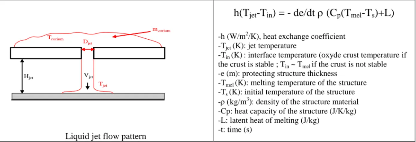
Investigation of several refractory materials (zirconia, alumina, molybdenum) have been made in order to assess the thickness (e) of material protecting the core catcher that can be eroded by liquid jets according to the flow pattern of FIG. 10. For a given material, the thermal erosion velocity depends on the jet impact duration at the same location, on the jet temperature (Tjet) and on the heat transfer coefficient (h) between the jet and the core catcher surface (FIG.10). Regarding the material mass expected to be relocated on the short term, physical analysis of parametrical calculations (FIG. 8) have shown that a bounding value of about 70% of the whole oxide material (UO2+MOX) inventory are relocated under the form
of hot jets consisting of mixture of oxide and steel. Moreover, in order to have a bounding value of jet temperature, possible super-heating of the liquid jet up to its boiling temperature is taken into account. So it means that about 25 t of MOX and 13 t of steel are considered to be relocated under the form of a liquid jet distributed over the DCS-M-TTs. Parametric calculations have been made by postulating the failure of a DCS-M-TT out of three when collecting the material mass aforementioned. The flow rate and consequently the time duration of the jet is supposed to be imposed by the jet diameter and its gravity fall velocity. So it leads to a calculated eroded thickness of the order from several tenths of centimetres up to 1 meter depending on the set of parameters used for the thermal loading assessment. The lower the diameter of the jet (the lower diameter considered is equal to the diameter of the DCS-M-TT where crossing the diagrid) the longer the ablation time is and the larger the eroded thickness. Finally, a significant uncertainty exists regarding the value to be taken for the heat transfer coefficient (h) in ASTRID accident conditions since the correlations have been established for different experimental conditions and this lead to a variation of the eroded thickness by a factor up to 4. Consequently, R&D efforts are foreseen in order to better assess the heat transfer coefficient. Moreover, R&D work is underway in order to assess the decrease of the erosion velocity by the jet when a liquid pool is formed at the impact point (so-called pool effect that enhances horizontal heat transfer at the place of axial one responsible for erosion). Future study insights are expected in order to go further on the core catcher design (SIMMER IV 3D calculations, physico-statistical tool insights, etc.). The possible loadings due to FCI in the lower plenum in case of fragmented jet will be assessed during the basic design as well. Long time cooling process does not exhibit any particular showstopper at this time but design verification studies are still under way.
Liquid jet flow pattern
h(Tjet-Tin) = - de/dt (Cp(Tmel-Ts)+L)
-h (W/m2/K), heat exchange coefficient -Tjet (K): jet temperature
-Tin (K): interface temperature (oxyde crust temperature if the crust is stable ; Tin ~ Tmel if the crust is not stable -e (m): protecting structure thickness
-Tmel (K): melting temperature of the structure -Ts (K): initial temperature of the structure -kg/m3density of the structure material -Cp: heat capacity of the structure (J/K/kg) -L: latent heat of melting (J/kg)
-t: time (s)
FIG. 10: Liquid jet impact pattern and thermal balance equation used to calculate structure erosion by assuming a stationary flow regime and stationary thermal exchanges regime
8. Verification of mitigation device design and of safety margins during the basic design
In the previous sections of this paper, the approach adopted to design the DCS-M-TTs and the core catcher has been presented. The main principles applied for designing is to get rid as far
mcorium Djet Vjet Hjet Tjet Tcorium
as possible from scenario dependency by investigating the various reactivity components that could enter into play during core degradation and by investigating on the basis of generic core degraded state the upper bound of each kind of loadings that the accident can induce (mechanical energy, local thermal loading, etc.). Following this approach, the mitigation devices have been pre-designed and their mitigation efficiency has been appreciated by comparing the accident effects with and without mitigation actions on degraded states studies but also on scenario calculations from the nominal state for ULOF. The confinement and the core catcher are therefore dimensioned independently from the scenario accident study results. For the confinement design, structure loading calculations are carried out by simulating the expansion of a gas bubble through parametrical studies. The objective is to define a confinement whose integrity limit is as high as possible considering the loadings postulated to design it. Once the mitigation devices are sized at best, verification studies will be carried out to check if there is a substantial difference between the loss of integrity limit (this loss can be expressed through a relay criterion called “criterion” on FIG. 11) of the considered component (primary vessel or core catcher) and the loading induced by the most likely expected scenario. This latter is assessed through a mechanistic calculation. Additionally, the spreading of this loading is assessed through physico-statistical calculations that have to demonstrate that the risk to exceed the criterion is low enough. Finally the combination of the difference between the best-estimate calculation and the criterion and the risk that the loading exceeds the criterion gives the margin between the loading and the design (or safety) criterion.
FIG. 11:Combination of mechanistic and physico-statistical calculations for margin assessment
9. Conclusions
Main severe accident scenario study results of interest for mitigation provision and associated device design have been presented in this paper. According to our calculation results, the good natural behavior of the CFV core during the primary phase of UTOP and ULOF should enable to avoid significant mechanical energy release. As far as the secondary phase is concerned, the consideration of a degraded state is aimed at getting rid of scenario-dependency in the design process of mitigation devices. The pre-design has been carried out thanks to parametric calculations (with dedicated fast-running models with easy ability to change their input parameters) that explore the whole range of free design parameters (number of corium paths, location, geometry, etc.). In addition, SIMMER III calculations have been performed for various imposed fuel specific powers in order to provide information on material flow-down in the mitigation tubes. Despite the good natural behavior of the core observed in the studies performed, the implementation of DCS-M-TTs (mitigation tubes) and of a core catcher in the primary vessel has been decided in order to better control the accident scenario and to mitigate very extreme situations. By merging core performance design
constraints and mitigation objective, three mitigation tubes have been implemented in the inner core and 18 tubes have been implemented at the outer core periphery. Their geometry, their location and their number have been consolidated thanks to a large number of parametric calculations of scenario evolution from a generic degraded state putting into play the dominant core reactivity effects. It has been evaluated that thanks to a fast draining of a part of the fuel from the core region through the mitigation tubes, the mechanical energy release is one order of magnitude lower with tubes than without tubes. The same result has been obtained in ULOF overall scenario calculations. Finally, by studying the different types of loading induced by scenario evolution from the degraded state aforementioned, it has been shown that liquid jet impingements are able to erode core catcher protective material. This loading being rather demanding in terms of overall reactor design, R&D is foreseen to reduce uncertainties on this value and to better take into account scenario consistency to define the loadings.
References
[1] GIF, 2002. A technology roadmap for Generation IV Nuclear Energy Systems, US DOE and the Generation IV International Forum.
[2] LE COZ P. et al., 2013. The ASTRID Project: status and future prospects, proceedings of FR13, Paris France 4-7 March 2013. Paper CN 199-261.
[3] PAPIN J., 2012. Behavior of Fast Reactor Fuel During Transient and Accident Conditions, Comprehensive Nuclear Materials, Elsevier Ltd.
[4] SCIORA P. et al., 2011. Low void effect core design applied on 2400 MWth SFR reactor, proceedings of ICAPP 2011, Nice, France.
[5] CHENAUD M.S. et al., 2013. Status of ASTRID core design studies at the end of predesign phase 1”, Nuclear Engineering and Technology, Vol. 45, N°6.
[6] BERTRAND F. et al., 2016. Comparison of the behaviour of two core designs for ASTRID in case of severe accidents. Nucl. Eng. Des. 297, 327–342.
[7] KONDO S. et al., “Phase 2 code assessment of SIMMER-III”, JNC TN9400 2000-105, September 2000.
[8] MARIE N. et al., 2016. A physical tool for severe accident mitigation, Nuclear Engineering and Design, Volume 309, 1 December 2016, Pages 224-235
[9] DROIN JB. et al., 2015. Analytical Modelling of the Primary Phase of an Unprotected Loss of Flow, Proceedings of Nureth 16, Chicago, Illinois, USA, 30 August - 4 September 2015
[10] MARIE N. et al., 2016. Physico-statistical approach to assess the core damage variability due to a total instantaneous blockage of SFR fuel sub-Assembly, Nuclear Engineering and Design, Volume 297, February 2016, Pages 343-353
[11] GEFFRAYE G. et al., 2011. CATHARE 2 V2.5_2: A single version for various applications, Nuclear Engineering and Design, Vol. 241, Issue 11.
[12] RUGGIERI, J.M., et al., 2006. ERANOS 2.1: International Code System for GEN IV Fast Reactor. ICAPP 2006, Reno, USA.
[13] MARREL A. et al., 2015. Advanced surrogate model and sensitivity analysis methods for sodium fast reactor accident assessment, Reliability Engineering and System Safety, Volume 138, June 2015, Pages 232-241
[14] BACHRATA A. et al., 2014. Unprotected Loss of Flow simulation on ASTRID CFV-V3 reactor core, Proceedings of ICAPP 2015, May 03-06, 2015 - Nice (France), Paper 15356


![Síntese da produção agropecuária do Espírito Santo 2016/2017 [recurso eletrônico].](data:image/gif;base64,R0lGODlhAQABAIAAAP///wAAACH5BAEAAAAALAAAAAABAAEAAAICRAEAOw==)