HAL Id: inria-00450409
https://hal.inria.fr/inria-00450409v2
Submitted on 21 Jun 2010
HAL is a multi-disciplinary open access
archive for the deposit and dissemination of
sci-entific research documents, whether they are
pub-lished or not. The documents may come from
teaching and research institutions in France or
abroad, or from public or private research centers.
L’archive ouverte pluridisciplinaire HAL, est
destinée au dépôt et à la diffusion de documents
scientifiques de niveau recherche, publiés ou non,
émanant des établissements d’enseignement et de
recherche français ou étrangers, des laboratoires
publics ou privés.
concept with HIPerNET
Pascale Primet Vicat-Blanc, Guilherme Koslovski, Fabienne Anhalt, Tram
Truong Huu, Johan Montagnat
To cite this version:
Pascale Primet Vicat-Blanc, Guilherme Koslovski, Fabienne Anhalt, Tram Truong Huu, Johan
Mon-tagnat. Exploring the Virtual Infrastructures as a Service concept with HIPerNET. [Research Report]
RR-7185, INRIA. 2010, pp.36. �inria-00450409v2�
a p p o r t
d e r e c h e r c h e
0249-6399 ISRN INRIA/RR--7185--FR+ENG Domaine 3Exploration du concept d’Infrastructures en tant que
Services avec HIPerNET
Pascale Vicat-Blanc Primet — Guilherme Koslovski — Fabienne Anhalt — Tram Truong
Huu — Johan Montagnat
N° 7185
Centre de recherche INRIA Grenoble – Rhône-Alpes
Pascale Vicat-Blanc Primet, Guilherme Koslovski , Fabienne
Anhalt , Tram Truong Huu , Johan Montagnat
Domaine : R´eseaux, syst`emes et services, calcul distribu´e ´
Equipe-Projet ANR CIS 06 HIPCAL 005
Rapport de recherche n° 7185 — January 2010 — 32 pages
R´esum´e : Dans le contexte de l’expansion et de la convergence du calcul et des communications, l’approvisionnement dynamique d’infrastructures distribu´ees personnalisables et la virtualisation des ressources sont des concepts et des tech-nologies prometteurs. Pour permettre aux utilisateurs de cr´eer et d’appr´ecier de telles infrastructures virtuelles, de nouveaux mod`eles et outils sont n´ecessaires. Ce rapport de recherche pr´esente le framework HIPerNET que nous concevons et d´eveloppons pour cr´eer, g´erer et contrˆoler des infrastructures virtuelles dans le contexte de l’Internet haut-d´ebit. L’id´ee cl´e de cette proposition est la com-binaison de la virtualisation du r´eseau et du syst`eme, associ´ees `a la r´eservation des ressources. Les motivations et les principes de conception d’HIPerNET sont pr´esent´es. Puis, nous introduisons le concept des infrastructures virtuelles, ap-pel´ees Virtual Private eXecution Infrastructures (VPXI). Pour aider `a sp´ecifier des infrastructures isol´ees et personnalis´ees, HIPerNET se base sur VXDL, un langage pour la description et la mod´elisation de VPXI, qui prend en compte ces ressources d’extr´emit´e ainsi que la topologie r´eseau virtuelle les intercon-nectant. Nous illustrons la sp´ecification, l’allocation et l’ex´ecution de VPXI en utilisant de r´eelles applications m´edicales distribu´ees `a grande ´echelle. Les r´esultats exp´erimentaux obtenus dans la plateforme Grid’5000 sont pr´esent´es et analys´es.
Mots-cl´es : HIPerNET, Infrastructures virtuelles, Iaas, Virtualisation R´eseau, VXDL, VPXI, Provisionnement, Isolation
Abstract: With the expansion and convergence of communication and comput-ing, dynamic provisioning of customized networking and processing infrastruc-tures, as well as resource virtualization, are appealing concepts and technologies. Therefore, new models and tools are needed to allow users to create, trust and enjoy such on-demand virtual infrastructures within a wide area context. This research report presents the HIPerNET framework that we are designing and developing for creating, managing and controlling virtual infrastructures in the context of high-speed Internet. The key idea of this proposal is the combina-tion of network- and system-virtualizacombina-tion associated with controlled resource reservation to provide fully isolated environments. HIPerNET’s motivations and design principles are presented. We then examine specifically how this framework handles the virtual infrastructures, called Virtual Private eXecution Infrastruc-tures (VPXI). To help specifying customized isolated infrastrucInfrastruc-tures, HIPerNET relies on VXDL, a language for VPXI description and modeling which considers end-host resource as well as the virtual network topology interconnecting them, including virtual routers. We exemplify the VPXI specification, allocation and execution using a real large-scale distributed medical application. Experimental results obtained within the Grid’5000 testbed are presented and analyzed. Key-words: HIPerNET, Virtual Infrastructures, IaaS, Network Virtualization, VXDL, VPXI, Provisioning, Isolation
1
Introduction
The expansion and convergence of computing and communication paint a new vision of the Internet : it is not only a black box providing pipes be-tween edge machines, but becomes a world-wide reservoir increasingly embed-ding computational and storage resources to meet the requirement of emerging applications[1]. Consequently, the promising vision of grid computing—to bring together geographically distributed resources to build very large-scale comput-ing environments for data- or computcomput-ing-intensive applications—along with the service wave led naturally to the ”Infrastructure as a Service” paradigm[2].
High-end applications present new challenges—e.g., the amount of data to process, the distribution of the data (wide-spreading of data sources over the territory), the heterogeneity of the data (lack of well-established standards), confidentiality—which results in high communication, storage, and computa-tion requirements. Intensive data-processing applicacomputa-tions require an access to in-frastructures with high-performance data-movement facilities coordinated with computational resources. However, current grid or cloud computing solutions[3, 4] built over traditional TCP/IP technology do not provide the performance isolation and predictability required by these users. Other applications need interconnections of large-scale instruments with high-performance computing platforms. The proposed best-effort approaches often result in user dissatisfac-tion and/or resource under-utilizadissatisfac-tion. Moreover, system and middleware het-erogeneity and complexity posed barriers to application portability. We expect future Internet applications will be more and more demanding in terms of se-curity, performance and quality of service. New technologies such as machine, links or router virtualization are now envisionned as solutions to these issues. Future applications may highly benefit from these innovations.
In this report, we argue that the extension of the Infrastructure as a Ser-vice paradigm to network resources is promising and powerful. We show how it can be implemented through the Virtual Private eXecution Infrastructure (VPXI) concept. Seen as a fundamental building block, VPXIs could mark a step forward in transforming the Internet into a huge, shared computing and communication facility. Any entity (individual user, community, government, corporate customer, high-level service provider) would dynamically rent the IT resources combined with the networking resources it needs to solve its specific problem. Based on this vision, this report presents HIPerNET, a framework to create, manage and control confined Virtual Private eXecution Infrastructures (VPXI) in a large-scale distributed environment.
In Section 2 we present the Virtual Private eXecution Infrastructure concept and the HIPerNET framework, highlighting the originalities of its design. Sec-tion 3 discusses the specificaSec-tion and allocaSec-tion process of VPXIs based on the VXDL, a language for virtual-infrastructure specification and modeling which considers end-host resources as well as virtual network topology, including vir-tual routers and timeline. In Section 4 we highlight the configuration step. The configuration of a VPXI is based on the instantiation of virtual entities as well as the configuration of various embedded mechanisms. Section 5 details the process for mapping an application on physical resources in a virtualized-infrastructure context. We illustrate application mapping through an example with the Bronze Standard workflow. In Section 6 we give experimental results obtained on the
Grid’5000 testbed. Related works are in Section 7 while conclusion and perspec-tives are developed in Section 8.
2
HIPerNET Concepts
2.1
Combining OS and Network Virtualization
The virtualization concept[5, 6, 7] enables an efficient separation between services or applications and physical resources. The virtual-machines paradigm is becoming a key feature of servers, distributed systems and grids as it provides a powerful abstraction. It has the potential to simplify resource management and to offer a great flexibility in resource usage. Each Virtual Machine (VM) a) provides a confined environment where non-trusted applications can be run, b) allows establishing limits in hardware-resource access and usage, through isola-tion techniques, c) allows adapting the runtime environment to the applicaisola-tion instead of porting the application to the runtime environment (this enhances application portability), d) allows using dedicated or optimized OS mechanisms (scheduler, virtual memory management, network protocol) for each applica-tion, e) enables applications and processes running within a VM to be managed as a whole.
A virtual private network is classically provisioned over a public network infrastructure to provide dedicated connectivity to a closed group of users. Resource-guaranteed VPNs[8] can be obtained from a carrier but are gener-ally static and require complex service level agreements (SLAs) and overheads. Tunneled VPNs [9] such as those in use over the Internet are more lightweight but offer low performance and no assured quality of service. The functionality required for the automating dynamic provisioning of lightpath or virtual private network capacities is emerging[10].
We propose here to combine and apply the concepts to both the IT re-sources and the network to enable the creation of multiple, isolated and pro-tected virtual aggregates on the same set of physical resources by sharing them in time and space. These aggregations of virtual resources organized with virtual interconnections are called Virtual Private eXecution Infrastructures (VPXI). Moreovoer, virtualizing routers and switching equipments opens an interesting door for the customization of packet routing, packet scheduling and traffic engi-neering for each virtual interconnection network. Router-function customization as well as data-plane virtualization offers a high flexibility for each infrastruc-ture. Therefore, conceptually, the virtual infrastructures are logically isolated by virtualization and enable the deployment of independant and customized bandwidth provisioning, channel encryption, addressing strategies. The isola-tion could also provide a high security level for each infrastructure. However, obtaining full performance and security isolation remains a key technical issue and most of the proposed virtual infrastructure frameworks do not address it properly.
2.2
HIPerNET and Virtual Private Execution
Infrastruc-tures concept
2.2.1 Design principles of the HIPerNET framework.
The HIPerNET framework combines system and networking virtualization technologies with crypto-based-security, bandwidth sharing and advance reser-vation mechanisms to offer dynamic networking and computing infrastructures as services. This framework is transparent to all types of upper layers : up-per layer protocols (e.g., TCP, UDP), APIs (e.g., sockets), middlewares (e.g., Globus [3], Diet [11]), applications, services and users. It helps end users with intensive-application deployment, execution and debugging, by providing an en-vironment to run them on scalable, controlled, distributed and high-capacity platforms. HIPerNET is also mostly agnostic of lower layers and can be de-ployed over IP as well as lambda networks.
The HIPerNET framework is responsible for the creation, management and control of dynamic entities called VPXIs, as defined in the next section, pro-viding a generalized infrastructure service. It supervises VPXIs during their whole lifetime. The key principle is to have operations realized automatically. For this, HIPerNET defines and activates mechanisms to automatically con-trol the VPXIs as well as the status of the underlying exposed substrate called HIPerSpace. HIPerNET integrates classical FACPS (fault-tolerance, account-ing, configuration, performance and security) management functions to these dematerialized entities. In the context of this report, we focus on two critical aspects of the virtualisation context : network configuration and performance isolation. Neither the security mechanisms—which are other key points of this framework [12]—relying on SPKI and the HIP protocol, nor the advance reser-vation algorithms or the migration mechanisms for fault-tolerance, are described in this report.
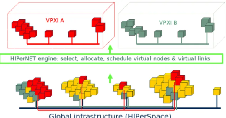
Figure 1 illustrates two virtual execution infrastructures (VPXI A and VPXI B ) allocated on a global exposed infrastructure (HIPerSpace) using the HIPer-NET framework1.
Fig. 1 – Example of a VPXI allocation on a distributed and virtualized HIPerSpace.
At the lower level, the HIPerNET framework accesses and controls a part of the physical infrastructure which is virtualized and called the HIPerSpace. Enrolled physical resources are then registered to the HIPerNET registrar and can be allocated to VPXIs. Once the resources have been exposed, HIPerNET gets full control over it. This set of exposed virtualized resources composes the substrate hosting the VPXIs. At run-time, the HIPerNET manager communi-cates with the nodes of the HIPerSpace to deploy virtual nodes, monitor their status and configure control tools to supervise the resource usage.
In this fully-virtualized scenario, HIPerNET interacts with multiple resource providers to plan, monitor and control them. Functions such as fault manage-ment, load balancing, bandwidth management and performance control are han-dled taking both network- and resource-virtualization techniques into account.
The current HIPerNET software implements virtual links at layer 3 of the OSI model (using IPsec and the HIP protocol [14]) enabling multiple virtual overlay networks to cohabit on a shared communication infrastructure. An over-lay network has an ideal vantage point to monitor and control the underlying physical network and the applications running on the VMs. All network over-lays and virtual end hosts are kept isolated both at the network and OS level to ensure security, performance control and adaptability. We also study the im-plementation of these virtual links at lower level (layer 2 or layer 1) within the CARRIOCAS project[10], [15].
2.2.2 Virtual Private Execution Infrastructure concept.
We define the Virtual Private eXecution Infrastructure (VPXI) concept as the HIPerNET’s management unit. VPXIs are an organized aggregation of vir-tual computing resources interconnected by a virvir-tual private overlay network for a defined time period. Ideally, any user of a VPXI has the illusion that he is using his own dedicated system, while he really is using multiple systems, part of the global distributed infrastructure. The resulting virtual instances are kept isolated from each others and the members of a VPXI have a consistent view of a single private TCP/IP overlay, independently from the underlying physical topology. A VPXI can span multiple networks belonging to disparate admin-istrative domains. In virtual infrastructures, a user can join from any location and use the same applications he was using on the Internet or its intranet.
Each VPXI is specified according to the user requirements. The specification is interpreted, allocated and configured using basic entities, which are building blocks composing the virtual execution infrastructures, as VXNodes : virtual end hosts, VXRouters : virtual routers, and VXLinks : virtual links.
VXNodes : Virtual end hosts. VXNodes or virtual end hosts are per-sonalized virtual machines that are allocated in physical hosts, and managed by HIPerNET to make sure they share the physical resources among them in a con-fined, secured and isolated way. Developed in accordance with the specifications of users and applications, each virtual end host can be parameterized (e.g., CPU, RAM memory, storage) and configured (e.g., operating system, communication tools) respecting the key set of parameters informed during their specification. Otherwise, end hosts can be organized individually or in groups, recursively. Basically, a VPXI represents a complex infrastructure, composed by individual end hosts that interact with groups (clusters or grids). Groups allow HIPerNET
to manage a set of virtual end hosts with the same characteristics all together, thus avoid unnecessary complex topologies and configuration scenarios. VXRouters : Virtual routers. Within the VPXI design, virtual routers, which we call VXRouters, are fully-personalizable components of the VPXIs. For example, these VXRouters, instantiated within physical Linux routers, will run inside isolated virtual machine instances. In our approach, all traditional network planes (data, control and management) are virtualized. Therefore, users can use any protocol and control mechanism on their allocated virtual router, and within the virtual interconnection network. HIPerNET implements a default routing mechanism on the virtual routers, but users can reconfigure it. They can deploy customized routing protocols, and configure the packet-queuing dis-ciplines, packet filtering and monitoring mechanisms they want. HIPerNET only manages the physical substrate and the resources attribution to each VXRouter. Also, VXRouters represent strategic points of the network for rate control as they concentrate aggregated VPXI traffic. By limiting the rate and policing the traffic of the different VXRouters, the traffic of VPXIs can be controlled and the user is provided with a fully isolated execution infrastructure. The control is implemented in the substrate, hence its implementation and management is transparent to the user. The advantage of having controlled environments is twofold : users have strong guarantees, while the network provider can better exploit the network by sharing it efficiently but differently between users. VXLinks : Virtual links. Virtual execution infrastructures can be composed by several VXNodes, groups of them, and VXRouters. All these components are interconnected using VXLinks or virtual links. Each VXLink is a temporary path allocated among multiple physical channels. As in a real infrastructure, each link can be parameterized with different metrics according to the applica-tions’ requirements. Metrics such as bandwidth, latency and direction can be valuated for each virtual link. Using the source-destination definition, it is pos-sible to organize the model of the virtual infrastructure, defining and asking for specific configurations in critical paths, that can interfere with the execution of applications.
HIPerNET comprises a module to specify virtual infrastructures. This mod-ule relies on the VXDL [16] language and provides users with a large flexibility in VPXI design as illustrated in the next section.
3
VXDL : Specifying and modeling Virtual
Pri-vate Execution Infrastructures
3.1
Needs for a specific language
Users need to define the virtual private execution infrastructures they request according to the applications’ requirements. This process requires a specific lan-guage to describe virtual resources and networks. Existing lanlan-guages are used in different areas of networks or IT resources management. The Common Infor-mation Model Specification (CIM) [17] provides a common set of objects and
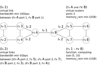
relationship among them. The CIM architecture is based on the UML concept and provides language CQL (CIM Query Language) to select sets of properties from CIM-object instances. CQL is a subset of SQL-92 with some extensions specific to CIM. In this case, CQL allows queries asking for a set of resources with certain configurations, but does not have parameters to interact with the allocation system, for example informing the basic location of a component. An other common example is the Network Description Language (NDL) [18]. NDL is a collection of schemas (topology, layer, capability, domain and physical) used to represent a network infrastructure at different levels. This language is guided by the Resource Description Framework (RDF) [19], a general-purpose language for representing information on the Web. Basically, RDF (and NDL) explores a graph data model composed by a set of RDF triples (a subject, an object and a predicate (property)). The triple concept is difficult to adapt to recursive de-scription, like groups or aggregates found in virtual infrastructures. A descriptive language dedicated to virtual infrastructures description must be more adaptive than conventional solutions and needs to combine the space and temporal as-pects of virtual infrastructures. During the specification process, new challenges coming from virtualization techniques have to complement the management, configuration and execution features of classical languages. We identify some desirable aspects that must be explored for descriptive languages : a) recursive representation of individual resources and groups ; b) each resource must be characterized using an extensible list of descriptive parameters to represent the necessary configuration—e.g., RAM memory, CPU speed, storage capability ; c) considering the configuration and deployment is also necessary to describe the software (e.g., operating systems) and tools (e.g., communication and pro-gramming tools) that must be used in VPXI ; d) each component (individually or in group) should be characterized as its elementary function, for example to describe a set of computing nodes or storage nodes ; e) it must be possible to express the composition of virtual network topology, detailing each virtual link. On the other hand, parameters should enable an abstract description, for example, informing a virtual link description that must be used to intercon-nect a group of resources ; f) the executing timeline of the infrastructure (this parameter should help in resources reservation and co-scheduling) ; g) security attributes for each resource element (access control, confidentiality level) ; h) commercial attributes for each resource element (maximum cost) ; and i) tem-poral attributes for each resource element (time window for provisioning). Within a given time slot, a VPXI can be formally represented as a graph— G(V, E)—where V is a set of vertices and E represents a set of edges. A vertex is in charge of active data processing functions and an edge is in charge of moving data between vertices. Figure 2 illustrates this concept, representing a virtual infrastructure composed by the aggregation of virtual machines interconnected via virtual channels. It shows two VXRouters (vertices rvA and rvB) which are
used to interconnect and perform the network control functions among the other virtual resources (vertices rv 1 to 8). These virtual routers can independently
forward the traffic of the different virtual infrastructures sharing the same phys-ical network. Each edge represents a virtual link used to interconnect a pair of virtual resources, which contains different configurations, as lv1 and lv2. Note
Fig. 2 – Example of a VPXI composition using graph notation.
To specify a virtual execution infrastructure we introduce VXDL (Virtual Resources and Interconnection Networks Description Language), a language that besides allowing end-resource description lets users describe the desired virtual network topology (using the same grammar), including virtual routers and timeline representation 2. Implemented with the XML standard, VXDL
helps users and applications to create or change VPXI specifications. The VXDL grammar is divided into Virtual Resources description, Virtual Network Topol-ogy description and Virtual Timeline description [16]. A new key aspect of this language is that all these basic descriptions are optional : it is possible to specify a simple communication infrastructure, or a simple end-ressource aggregate.
3.2
Virtual resources description
The key point explored in this part of the VXDL grammar is enabling users and applications to describe in a simple and objective way all the necessary end hosts, and groups of them. The parameters proposed in VXDL are directly related to virtual infrastructures, and besides allowing basic resource parameter-ization (e.g., maximum and minimum values acceptable to RAM memory and CPU frequency), VXDL lets users directly interact with management frame-works (such as HIPerNET). For this reason, VXDL suggests the definition of parameters such as anchor, number of virtual machines allocated per physical host, and key components.
The anchor parameters act in the physical allocation of a VPXI. We know that in a virtualized substrate the VPXI can be allocated anywhere, but some-times it is necessary that a virtual end host (or group) must be positioned in a physical location (e.g., a site or a machine—URL, IP) in accordance with a basic location. Yet, analyzing a virtualized substrate, multiple virtual machines can be allocated in the same physical host, sharing the real resources among them. VXDL enables the definition of a maximum number of virtual machines that must be allocated in a physical host, enabling users to interact directly with the allocation algorithm. The key parameter acts in the identification of
2More information about VXDL is provided on http://www.ens-lyon.fr/LIP/RESO/
Fig. 3 – A graph representing a network topology.
the most important components of the VPXI. This information will help in the allocation, informing that the component must be allocated in advance.
3.3
Virtual network topology description
VXDL improves the network topology description in two key points : I) en-abling the specification together with other components, using the same gram-mar ; II) applying the concept of link organization, which permits a simple and abstract description. Links can define connections between end hosts, between end hosts and groups, inside groups, between groups and VXRouters, and be-tween VXRouters. Using this concept users can model their VPXIs in accor-dance with their applications. Figure 3 presents a possible VPXI composed by two groups (clusters), each with 8 nodes interconnected using 2 VXRouters.
In VXDL grammar, the definition of source-destination pairs for each link is proposed. A single link can be applied to different pairs, simplifying the spec-ification of complex infrastructures. For example, links used to interconnect a homogeneous group, such as a cluster, can all be defined in a same link descrip-tion. Each link can receive a parameterization involving latency, bandwidth and direction. To latency and bandwidth, the maximum and minimum values are applied.
3.4
Virtual timeline description
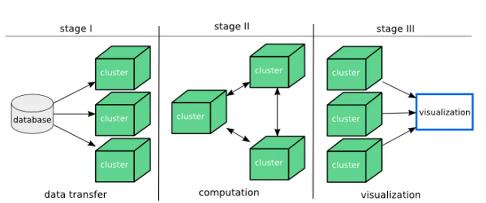
Any VPXI can be permanent, semi-permanent or temporary. The VPXIs are allocated for defined lifetime in time slots. Time slots are configurable param-eters and are specific to the HIPerSpace. Often the VPXI components are not used simultaneously or all along the VPXI’s lifetime. Thus, the specification of an internal timeline for each VPXI can help the middleware in the allocation, scheduling and provisioning processes. Periods can be defined in function of their usages, as data transfer or computation, delimited by temporal marks. A period can start after the end of another period or after an event. Looking at figure 4 we can observe three execution stages of an application. This VPXI is composed by one data storage cluster, three computation clusters and one visualization cluster, all interconnected through virtual links. In stage I, it is necessary to perform a data transfer between the storage cluster and the computation clus-ters. During this transfer, a high-bandwidth configuration is required, which is not necessary in the others stages. As early as in stage II, the three computation clusters execute an application, possibly requesting links with a low latency in communication to the substrate framework. Finally, stage III asks for a high bandwidth again to perform the data transfer and results visualization. In this
Fig. 4 – Example of a virtual timeline definition.
example, the periods between stages I and II or stages II and III can be defined in a relative way : after the data transfer, in stage II, computation starts and the low latency on the intra-cluster links is implemented. VXDL explores the relative definitions using common parameters as start, after and until.
4
Deployment and provisioning of VPXIs
In a typical scenario, HIPerNET receives a user’s VPXI request, specified in VXDL. The software interprets it, then checks its feasibility and potentially negotiates security, performance, planning and price with the customer or its representative. When an agreement has been found, a VPXI instance is allocated and scheduled as proposed in [20]. The VPXI is then provisionned according to the schedule. Finally, the deployment of a VPXI consists in instantiating and configuring the specified virtual entities (VXNodes, VXRouters and VXLinks) on top of the physical substrate. First, all the virtual nodes (end hosts and routers) are deployed, then the virtual links and routes are set up. Routes are configured individually in all the VXNodes and VXRouters. During the VPXI’s lifetime, its allocation may change as described in section 3.4. In this case, if the topology changes, new VXLinks are deployed if necessary and the routes are reconfigured in all the VXNodes and VXRouters to reconnect the topology. Below, we describe the mechanisms that are deployed to virtualize the network resources.
4.1
VPXI network resource provisioning
Virtual infrastructures share a physical substrate network. To ensure VPXI isolation, the resource sharing between different virtual infrastructures needs to be finely controlled. To achieve this, a set of control mechanisms residing inside the physical substrate nodes are set up. They are in charge of super-vising, at runtime, how the physical capacity is allocated to the virtual nodes and links. After the VPXI allocation and scheduling process, virtual capacities are assigned to each virtual node and link. Then, these capacities are reserved and provisionned in the physical substrate. During the deployment phase, the control tools are invoked at each involved substrate node, in order to enforce allocations during the VPXI lifetime. At runtime, the control tool’s actions can
be reconfigured when the VPXI’s requirements change. This happens for ex-ample when the execution moves from one stage to the next. At that moment, HIPerNET updates the configuration of the deployment according to the allo-cation corresponding to the new stage. Thus, it reconfigures the control tools, in order to change the resource attribution. The control tools have three main features : they manage the bandwidth, CPU and memory sharing among the virtual domains, so that they offer the user provisionned VPXIs according to his requirements.
During the negotiation, a VPXI user can specify a desired bandwidth per virtual link, associated to one of the following services :
– Guaranteed minimum : the minimum rate that has to be available on the virtual link at any moment ;
– Allowed maximum : the maximum capacity the virtual link must allow at any moment ;
– Static reservation : in this case, the guaranteed minimum is equal to the allowed maximum.
The user can use one of these services to specify its application’s requirements. A user who wants to execute, for example, a distributed application commu-nicating with MPI will specify a guaranteed minimum rate which can not be decreased during negotiation. If the user specifies an allowed maximum, the ne-gotiation will result in a bandwidth equal or below this maximum. This link is shared in a best-effort way with other traffic. Specifying a static rate gives the user the impression that he works in a dedicated physical network whose links have the specified capacity. He will be able to obtain the specified bandwidth at any moment but can never exceed it. This kind of service allows no negotiation and could for example help with conducting reproducible experiments where link availability should not vary.
According to these user specifications and the free capacity on the physical substrate, a static bandwidth reservation is made. Then, HIPerNET’s control mechanism allocates the maximum bandwidth for each virtual link in order to guarantee the negociated bandwidth. The configuration takes place on both ends of the virtual link configuring the physical interfaces.
Let’s consider two users of two VPXIs who specified different rates for the different virtual links. The user of VPXI 1 desires a bandwidth of 100 Mb/s on virtual link A (VL A) and a bandwidth of 200 Mb/s on VL B connected to VXRouter (VXR) 1. The user of VPXI 2 wants both virtual links connected to VXRouter 2, VL C and VL D, to allow 400 Mb/s. Figure 5 shows the specified virtual network configurations of VPXI 1 and VPXI 2. HIPerNET configures the virtual link rates to these values during the deployment of VPXI 1 and VPXI 2.
Users can also specify a maximum percentage of the physical CPU a virtual node of a VPXI should be allowed to use. This quantity of CPU is allocated in the available CPU of the physical machine. The available quantity of CPU corresponds to the CPU of the physical machine minus the part of the CPU in use for the machine’s host system, or domain 0 (dom0) in the Xen terminology. CP Uavailable= CP Umachine− CP Udom0
Dom0 consumes a small part of CPU time for the control mechanisms and a considerable part for networking as it is in charge of forwarding the packets of all the virtual machines, or domains U (domUs).
Fig. 5 – User bandwidth specification for two VPXIs.
CP Udom0= CP Ucontrol+ CP Unetworking and CP Ucontrol CP Unetworking
So CP Udom0 can be established according to the sum of the maximum rates
specified by all the domUs hosted on the considered physical machine. In Sec-tion 6.3, this relaSec-tionship is evaluated on virtual routers.
The next section gives more details on the VXRouters.
4.2
Implementation of VXRouters
In the current HIPerNET implementation, the VXRouters consist in software routers implemented inside virtual machines. These VXRouters are hosted by network-aware servers. We call them HPSRouters (High Performance Software routers) as they are commodity servers with the required hardware to support high-performance networking (several network interface cards, several CPUs and a huge amount of memory) used as Linux routers. Current commercial virtual or logical routers do not support the full virtualization of the router data planes. The performance impact of the data-plane virtualization is indeed an issue. However, recent analysis have demonstrated that modern virtualization techniques are improving rapidly, making our VXRouter approach interesting and promising [21]. Figure 6 shows an example of a physical router hosting two VXRouters. These virtual routers have to share the physical resources of the machine and additional processing is necessary.
Customized routing and traffic-engineering functions can be set up on the VXRouters. A VPXI user can, for example, choose to adapt the routing in order to satisfy specific Quality of Service requirements, as illustrated in Figure 7.
In this example, latency-sensitive traffic and bandwidth-aware traffic are routed on different paths. 1 Gb/s links are allocated between each one of the three VXRouters to transmit latency sensitive traffic. All high-throughput traf-fic, which can be pipelined, is redirected over Site 2. The advantage of this rout-ing scheme is that the user needs to provision only 2 links with 5 Gb/s instead of 3. As presented in [22], this is an example of efficient channel provisioning combining routing and traffic engineering.
Fig. 6 – Model of a physical router hosting VXRouters.
Fig. 7 – Example of bandwidth allocation for latency-sensitive and high-bandwidth flows.
5
Executing distributed applications on
virtual-ized infrastructures
Programming applications on large-scale distributed environments is diffi-cult. Defining the optimal infrastructure to execute them is another issue. The flexibility offered by virtual infrastructures could make the problem even more complex. Promising work on workflow has been done in the area of application development to optimize their usage of distributed environments. We propose to explore how this work can also benefit to the composition of virtual infras-tructures.
In our model, the application-mapping process is separated in three steps : I) workflow generation : the workflow is generated using information ex-tracted from the application, such as benchmarks results, data input descrip-tion, data transfer in each module, and the number of nodes required to perform a satisfactory execution.
II) workflow translation into VXDL : taking into account the application’s requirements (RAM configuration, CPU speed, and storage size), users can de-velop a VXDL description, asking for the desirable configuration of the VPXI. At this point users can also declare that some components must be allocated in a specific location as well as define the virtual network topology specifying the proximity (latency configuration) of the components and the needed bandwidth. III) VPXI allocation : in this step VPXI management framework will allo-cate the virtual components respecting the configuration expressed by the user
(such as parametrizations and time periods organization). In a second phase, the software configuration (OS, programming and communication tools), extracted directly from the application and described using VXDL, will be deployed within the virtual machines that compose the VPXI.
5.1
Workflow language
Complex applications able to exploit large scale distributed environments are generally described with workflows. These workflows are interpreted by en-gines that convert the description of work in execution scripts. Several workflow languages have been proposed in the literature. On grid-based infrastructures, Directed Acyclic Graph (DAG)-based languages such as the MA-DAG language, part of the DIET middleware [11], have often been used. They provide a explicit, static graph of all computing tasks to be performed. To ease definition of grid ap-plications with a complex logic to be represented, more abstract language have been introduced. For instance, Scufl was introduced within the myGrid project3 to present data flows enacted through the Taverna workflow engine [23]. It is one of the first grid-oriented data flow languages that focuses on the application data flow rather than on the generated graph of tasks. The GWENDIA language4
considered in this paper is a data-flow oriented language that aims at easing the description of the complex application data flows from a user point of view while ensuring good application performances and grid resources usage. An example of a graphic representation of workflow description is given in figure 8. In this figure Floating and Reference are representing data unit to be processed and CrestLines, CrestMatch, PFMatchICP, PFRegister, Yasmina and Baladin are processing units. Floating and Reference represent groups of data items to be processed : processing units will be invoked as many time as needed to process all data items received. The user describing the application focus on the data processing logic rather than on the execution schedule. The structural applica-tion workflow is transformed into an execuapplica-tion schedule dynamically, while the workflow engine is being executed.
GWENDIA is represented in XML using the tags and syntax defined below : Types : values flowing through the workflow are typed. Basic types are integer, double, string and file.
Processors : a processor is a data production unit. A regular processor invokes a service through a known interface. Special processors are workflow input (a processor with no inbound connectivity, delivering a list of externally defined data values), sink (a processor with no outbound connectivity, receiving some workflow output) and constant (a processor delivering a single, constant value).
Processor ports : processor input and output ports are named and de-clared. A port may be an input (<in> tag), an output (<out> tag) or both an input/output value (<inout> tag). The input ports also define iteration strate-gies that control the number of invocation of the processor as a function of its inputs.
Data link : a data link is a simple connection between a processor output port and a processor input port.
3myGrid UK e-Science project : www.mygrid.org
4GWENDIA is defined in the context of the ANR-06-MDCA-009 GWENDIA project :
CrestLines Floating Reference CL_size CrestMatch PFMOpt PFMatchICP Yasmina YasminaOpt Baladin BaladinOpt PFRegister Results
Fig. 8 – Bronze Standard workflow
Workflow managers are associated with these workflow language and are in charge of optimizing the execution of workflows. For example, MOTEUR [24] is a data-intensive grid-interfaced workflow manager. MOTEUR can enact a workflow represented in Scufl language or in GWENDIA language and submits the workflow tasks to a grid infrastructure. To optimize the execution, it enables three levels of parallelism : workflow parallelism, data parallelism and pipelining.
5.2
Workflow translation into VXDL
A workflow description represents the input/output data, the processors (a data-processing module), and the relationship between an application’s pro-cessors. In our model, the workflow description will be translated in a VPXI description, specified in VXDL. Generally, to execute a complex application in a virtualized infrastructure, one has to consider that a middleware has to su-pervise the execution of the different tasks. In our example, the workflow engine (MOTEUR) and a specific task scheduler are executed for every application on independent computing resources. Input data and the intermediate results also require the presence of a file server. Therefore the VXDL description of any VPXI executing an application controled by the MOTEUR engine will contain a generic part describing these 3 nodes.
The variable part of the VPXI description directly depends on the informa-tion extracted from the workflow such as input data, the number of processors, and the links between the processors. The computation time, the data volume and the number of invocations of each module is another information that can be extracted from the workflow. Given p the number of processors (modules) of an application, the user can naively request n virtual computing resource and evenly split the set of resources among the workflow processors. Each module therefore has n/p resources. This will of course be sub-optimal since the
proces-sors have different execution times. A first variant of this naive strategy could take into account extra information on the benchmarked execution time of each module.
5.3
Medical application example
Let us illustrate this VPXI description and embedding problem through a complex, real-scale medical-image analysis application known as bronze stan-dard.
The bronze standard [25] technique tackles the difficult problem of validat-ing procedures for medical-image analysis. As there is usually no reference, or gold standard, to validate the result of the computation in the field of medical-image processing, it is very difficult to objectively assess the results’ quality. The statistical analysis of images enables the quantitative measurement of computa-tion errors. The bronze standard technique statistically quantifies the maximal error resulting from widely used image registration algorithms. The larger the sample image database and the number of registration algorithms to compare with, the most accurate the method. This procedure is therefore very scalable and it requires to compose a complex application workflow including different registration-computation services with data transfer inter-dependencies.
Bronze standard’s workflow is enacted with the data-intensive grid-interfaced MOTEUR workflow manager [24] designed to optimize the execution of data-parallel flows. It submits the workflow tasks to the VPXI infrastructure through the DIET middleware [11], a scalable grid scheduler based on a hierarchy of agents communicating through CORBA.
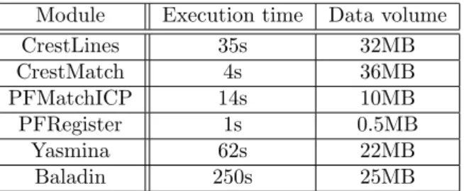
The estimated algorithm performance is valid for a typical database image. In the experiments reported below, we use a clinical database of 32 pairs of patient images to be registered by the different algorithms involved in the work-flow. For each run, the processing of the complete image database results in the generation of approximately 200 computing tasks. As illustrated in figure 8, the workflow of the application has a completely deterministic pattern. All pro-cessors of this application have the same number of invocations. The execution time and the data volume transferred of each processor have been mesured in initial microbenchmarks reported in table 1.
Module Execution time Data volume CrestLines 35s 32MB CrestMatch 4s 36MB PFMatchICP 14s 10MB PFRegister 1s 0.5MB Yasmina 62s 22MB Baladin 250s 25MB
Tab. 1 – Execution time and processed data volume for each module of bronze standard.
Let us now consider a request for a VPXI composed of 35 nodes to execute Bronze Standard’s workflow. Three nodes will be dedicated to the generic part : 1 node for MOTEUR, 1 node for the middleware server and 1 node for the database server. The 32 nodes left are distributed and allocated proportionally
to the execution time of the workflow processors : 3 nodes for CrestLines, 1 node for CrestMatch, 1 node for PFMatchIP, 1 node for PFRegister, 22 nodes for Baladin, and 4 nodes for Yasmina. Then, for this same computing-resources set, several variants of VPXI descriptions with different network topologies can be expressed. We exemplify developing two different VPXI descriptions. The listing below presents a VXDL description of a virtual node (MOTEUR) and a computing cluster (Baladin).
Fig. 9 – VPXI description of the bronze standard’s workflow.
Figure 9 illustrates the description of a VPXI using graphs. All components and network links required to execute bronze standard’s workflow are repre-sented. We developed two descriptions considering this scenario : in VPXI 1 the network is composed by two links type, one with low latency intra cluster and the other one with a maximum latency of 10 ms to interconnect the clusters. In VPXI 2 the network comprises three virtual links : one with a low intra-cluster latency (maximum latency of 0.200 ms), another one with a latency of 10 ms interconnecting the components except one asking for a maximum la-tency of 0.200 ms to interconnect CrestMatch (dark blue) with the components PFMatchICP, Yasmina and Baladin (blue in the figure).
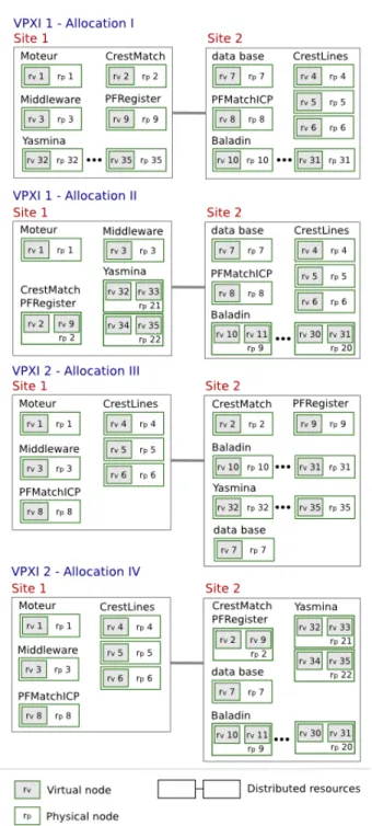
Let us now illustrate how each VPXI description can be embedded in a physical substrate. We propose two different solutions for both VPXI, which correspond to four different physical allocations as represented in figure 10. In this example, Site 1 and Site 2 represent two geographically-distributed-resources sets.
In VPXI 1 - Allocation I, intra-cluster link specification enables the al-location of loosely connected resources. In this embedding solution, 1 virtual machine per each physical node is allocated.
In VPXI 1 - Allocation II each physical node in clusters CrestMatch, PFRegister, Yasmina, and Baladin are allocated 2 virtual machines.
The VPXI 2 - Allocation III respects the required interconnection allo-cating corresponding resources in the same physical set of resources (such as
Fig. 10 – Allocations of descriptions VPXI-1 and VPXI-2.
a site in a grid). This embedding solution explores the allocation of 1 virtual machine per physical node.
VPXI 2 - Allocation IV explores the same physical components as Allo-cation III but allocates 2 virtual machines per physical node in the CrestMatch, PFRegister, Yasmina, and Baladin clusters.
6
Experiments
This section presents experimental results of the current implementation of network virtualisation in HIPerNET. Rate control for bandwidth provisioning, performance isolation and the CPU cost of bandwidth are investigated. To in-stantiate virtual end hosts and virtual routers, we chose to use the Xen [6] technology because of the offered flexibility : distinct operating systems with distinct kernels can run in each virtual machine and the user is provided with full configurability to implement individual virtual networks. All the experi-ments are executed within the Grid’5000 [26] platform, using Xen 3.2 and IBM Opteron servers with one 1 Gb/s physical interface. The machines have two CPUs (one core each).
6.1
Context : Adaptation to Grid’5000
The HIPerNET software is currently being adapted to Grid’5000 [26], the national experimental shared facility, to enable reproducible experiments on cus-tomizable topologies. Figure 11 represents the Grid’5000 testbed with its nine
Fig. 11 – Grid’5000 infrastructure with HPSRouters.
sites interconnected with 10 Gb/s dedicated lambdas. An HPSRouter is inserted on each site. These machines host VPXI’s VPXRouters to support diverse rout-ing strategies and innovative transport protocols. Another goal is to control the bandwidth-sharing of the physical inter-site links for isolated, controlled, and reproducible experiments. VPXIs can be reserved and deployed over several ge-ographically distributed sites. Figure 12 represents an example of three VPXIs, extended over three distinct sites. Each site is provided with a HPSRouter host-ing one VPXRouter per VPXI. Those virtual routers are gateways, forwardhost-ing all the traffic of a VPXI between the site’s LAN and the interconnection net-work. With this model, the VPXRouters are able to control the traffic of the VPXIs and their bandwidth sharing of the physical links over the backbone network. The VPXRouters are interconnected over the backbone across several hops via IP-tunnels giving the VPXI user the illusion that the different parts of
Fig. 12 – Allocation of 3 VPXIs in the Grid’5000 infrastructure.
his VPXI are directly interconnected by a single router, even though they are in reality located on distant physical locations.
To face scalability issues, we assume that at a given time, only a limited num-ber of experiments will request for a confined VPXI and a dedicated channel (for example, 10%=1 Gb/s). The others, which are considered not ”commu-nication sensitive”, will run without any network control in the classical and fully-transparent best effort mode. The aggregated bandwidth allocated to the VPXI is limited to a configurable percentage of the access link’s capacity. The shaped VPXI-traffic leaving the physical routers hosting the VPXRouters is fully isolated from the remaining best-effort traffic of Grid’5000. To guaran-tee this, the switch where the VPXRouter-traffic and the Grid’5000 best-effort traffic come together distinguishes the two traffics and gives a strict priority to the VPXRouter-traffic. The background traffic, i.e. all the traffic that does not require specific treatment, is forwarded through the classical best effort path.
6.2
Rate control and performance isolation experiment
The goal of this experiment is to evaluate the isolation between VXRouters when their are mapped on the same physical router.
6.2.1 Experimental setup
Two VXRouters called VXR1 and VXR2 share one physical machine to forward the traffic of two VPXIs (VPXI 1 and VPXI 2). Each virtual router has two virtual interfaces connected to two virtual links as represented on Fig-ure 13. These links are configFig-ured to allow a maximum bandwidth R of respec-tively RV LA = RV LB = 150M b/s and RV LC = RV LD = 300M b/s. Figure 13
represents this setup.
Three cases of user traffic can be distinguished by
1. in-profile traffic : the sum of the traffic on virtual link X is smaller than the allowed maximum rate RV LX;
2. limit traffic : the sum of the traffic on virtual link X is equal to the allowed maximum rate ;
Fig. 13 – Experimental setup with 2 VPXIs with different bandwidth require-ments.
3. out-of-profile traffic : the sum of the traffic on virtual link X exceeds the allowed maximum rate.
This experiment aims at determining if the traffic-control techniques limit the traffic to the desired rate and if isolation is guaranteed. Isolation means that limit or out-of-profile traffic should have no impact on the available bandwidth on the physical link, and thus none on the available bandwidth of concurrent virtual links.
Table 2 lists four testcases to validate our implementation. In this exper-iment, we suppose a congestion factor (CF) of 0.8 for in-profile traffic which means that traffic is sent at 80% of the maximum allowed speed. Limit traffic has a CF of 1 and for out-of-profile traffic, a CF of 1.2 is chosen.
VPXI 1 VPXI 2 Case 1 in profile in profile Case 2 limit limit Case 3 in profile limit Case 4 in profile out of profile Tab. 2 – User traffic for different test cases.
One flow is sent from virtual end hosts Ai and Ci to the corresponding
virtual end hosts Bi and Di, respectively. The flows are sent in the different
cases so that their sum on each VXRouter corresponds to the profile specified in Table 2.
6.2.2 Results
The results of these experiments show that the desired rate on each virtual link can be obtained with our configuration and that out-of-profile traffic does not impact other traffic sharing the same physical link.
In case 1, where all the traffic is in profile, requiring less bandwidth than allowed, each flow gets its desired bandwidth and no packet loss is detected with UDP. For case 2, the flows try to get 100% of the maximum available bandwidth. This causes some sporadic packet losses which cause some instan-taneous throughput decreases in TCP as illustrated in Figure 14. The overall throughput still reaches the allowed maximum value.
Fig. 14 – Test case 2 : TCP Rate with VPXI 1 and 2 being at the limit rate (with a congestion factor(CF) of 1).
Fig. 15 – Test case 4 : TCP Rate with VPXI 1 being in profile and VPXI 2 out of profile (with a congestion factor(CF) of 1.2).
Figures 15 and 16 show respectively the results with TCP and UDP flows in testcase 4 where the two flows of VPXI 1 are in profile, their sum 30 + 90 = 120M b/s does not exceed the maximum allowed value of 150M b/s. With TCP and UDP, both flows attempt their desired rate and with UDP, no loss is de-tected. The two flows of VPXI 2 try to exceed the allowed value of 300M b/s by sending at 120 + 240 = 360M b/s. As a result, they see some of their pack-ets dropped at the incoming interface of the physical router. TCP reacts in a sensitive way to this packet drop. It tries to share the available bandwidth by
Fig. 16 – Test case 4 : UDP Rate with VPXI 1 being in profile and VPXI 2 out of profile (with a congestion factor(CF) of 1.2).
the two flows. So flow 1 gets generally the 120M b/s as it is less than half of the available 300M b/s. Flow 2 requiring 240M b/s varies a lot to get also an average throughput of about half of the 300M b/s.
With UDP (Figure 16), the packet drop of the flows of VPXI 2 causes a regular decrease of the bandwidth. Flow 1 looses an average 13% of its packets and flow 2 an average of 18% of its packets. The average of these two values is slightly smaller than the percentage of exceeding packets (1 − (1/1.2) = 16.6%) implied by the congestion factor of 1.2.
These results show that only flows which try to exceed the fixed limit band-width are penalized in this configuration. In profile and even limit flows are not impacted. In this way, individual rate sharing is efficient in this model and isolation is guaranteed.
6.3
CPU cost of bandwidth
To find out how much CPU is needed to forward flows in domain U, making use of data-plane virtualization, and how this value depends on the forwarding rate, this experiment measures the CPU usage of Xen during forwarding on VXRouters with different rates. This experiment is executed with 1, 2 and 4 concurrent VXRouters on a single physical router, each one forwarding a sin-gle UDP flow with different rates. The rate of each flow is incremented every 60 seconds so that the aggregate rate on the set of virtual routers increments by 10 Mb/s. During each interval, the CPU use of the physical router is mea-sured with the xentop tool. Figure 17 shows the CPU utilization of dom0 of the physical router in the different cases. It increases with the increasing aggregate forwarding rate in the VXRouters. Surprisingly, this overhead does not signif-icantly vary with different numbers of VXRouters. It is even almost identical when 2, 4 or 8 VXRouters are forwarding simultaneously flows.
Fig. 17 – Dom0 CPU use with 1, 2, 4 or 8 concurrent VXRouters forwarding UDP flows.
Fig. 18 – DomU CPU use with 1, 2, 4 or 8 concurrent VXRouters forwarding UDP flows.
The corresponding CPU utilization of a domU during the same experiments is represented on Figure 18. The overhead increases with the forwarding rate, but in the case of dom0, it does not increase with the number of concurrent VXRouters. Only the cost of a single VXRouter represents an exception.
This means that the CPU cost of a physical router hosting VXRouters depends strictly on the aggregate forwarding rate and not on the number of VXRouters it hosts.
6.4
Medical imaging application deployment on the testbed
For testing VPXIs, a system image containing the operating system based on a standard Linux distribution Debian Etch with a kernel version 2.6.18-8 for AMD64, the domain-specific image processing services and the middleware components (MOTEUR and DIET) was created. The experiments on the VPXIs described in the section 5.3 were performed. In each experiment, we repeated the application 10 times to measure the average and standard deviation of the ap-plication makespan, the data transfer and task execution time. The physical in-frastructure is reserved on the Grid’5000 clusters : capricorne (Lyon), bordemer (Bordeaux) and azur (Sophia) which CPUs are 2.0 GHz dual-cores Opterons. The distance between clusters is 500km and they are connected through 10Gbps links. Each VPXI is composed of 35 nodes divided in generic and variable part : 3 nodes are dedicated to generic part (MOTEUR, DIET, file server) using 1 CPU per node and the remaining 32 nodes of the variable part are allocated dependently on the VPXIs (VPXI 1 - Allocation I and VPXI 2 - Allocation III used 1 CPU per node while VPXI 1 - Allocation II and VPXI 2 - Allocation IV used 1 CPU core per node).
Coallocating resources on one grid site : the application’s makespan on the VPXI 2 - Allocation III and VPXI 2 - Allocation IV is 11min 44s (±49s) and 12min 3s (±50s) respectively. This corresponds to a +3.8% makespan increase, due to the execution overhead when there are two virtual machines collocated on the same physical resource. Indeed, we present in the table 3 the average execution time of application services on the VPXI 2 - Allocations III and IV. We can observe that the average execution overhead is 5.17% (10.53% in the worst case and 1.28% in the best case).
Services Allocation III Allocation IV variation CrestLines 34.12 ± 0.34 36.84 ± 5.78 +7.97% CrestMatch 3.61 ± 0.48 3.99 ± 0.63 +10.53% PFMatchICP 11.93 ± 2.76 12.75 ± 5.35 +6.87% PFRegister 0.78 ± 0.18 0.79 ± 0.18 +1.28% Yasmina 59.72 ± 14.08 61.53 ± 13.98 +3.03% Baladin 244.68 ± 16.68 247.99 ± 19.51 +1.35% Tab. 3 – Execution time on VPXI 2 - Allocations III and IV
Resources distributed over 2 sites : when porting the application from a local infrastructure to a large scale infrastructure, the data transfer increases. Table 4 presents the data transfer time (s) of the application services on VPXI 2 - Allocation IV (local) and VPXI 1 - Allocation II (distributed over 2 sites). The measured overhead is 150% in the worst case. Conversely, some local transfers may be slightly reduced. In the case of our application however, this overhead has little impact on the application makespan since it is compensated for by the parallel data transfer and computations. Indeed, the makespan is 12min (±12s) and 12min 11s (±20s) on VPXI 1 - Allocation I and VPXI 1 - Allocation II respectively, very similar to the performance of VPXI 2 - Allocation IV.
Resources distributed over 3 sites : further distributing computational resources causes an additional increase of the data-transfer overheads. An ad-ditional experiment with VPXI 1 - Allocation II the generic part of which is
Services Allocation IV Allocation II variation CrestLines 2 ± 0.45 3.01 ± 1.6 +50.5% CrestMatch 1.99 ± 0.34 1.83 ± 0.36 -8.04% PFMatchICP 1.3 ± 0.4 3.25 ± 0.13 +150% PFRegister 0.51 ± 0.23 0.43 ± 0.09 -15.69% Yasmina 1.19 ± 0.27 1.16 ± 0.21 -2.52% Baladin 1.17 ± 0.38 1.81 ± 1.03 +54.7%
Tab. 4 – Data transfer time on the local VPXI 2 - Allocation IV and large scale VPXI 1 - Allocation II infrastructure
located in Lyon while the variable part is randomly distributed in Lyon, Bor-deaux and Sophia leads to a makespan of 12min 13s (± 30s) with a data-transfer overhead of 176% in the worst case.
7
Related work
Infrastructure virtualization is a hot topic studied in several projects [27, 28, 29]. In [27], the authors propose VINI, a virtual network infrastructure that al-lows several virtual networks to share a single physical infrastructure, similarly to HIPerNET. Researchers can run experiments in virtual network slices with XORP routing software, running inside UML instances. They can configure it and choose a protocol among the available ones. HIPerNET pushes this facil-ity a step further adding data-plane virtualization and allowing users to chose the operating system and install any routing software. This also provides full isolation between virtual nodes and controlled resource sharing. VINI has dedi-cated IP address blocks, HIPerNET interposes a HIP-layer between the network and the application levels, that provides each resource with a unique identifier (HIT).
Trellis [30] is a network-hosting platform deployed on the VINI facility. Like HIPerNET, it is a virtual-network substrate that can run on commodity hard-ware. It is implemented using VServer’s [31] container-based virtualization be-cause of its networking performance. For the reasons described before, we use the Xen hypervisor which has become promising in terms of its growing network performance in its recent versions.
VINI and Trellis are evaluated on PlanetLab [32] which provides users with slices of virtual ressources distributed among its overlay infrastructure. Those virtual resources are VServers providing generally end-host functionalities. In HIPerNET, we chose to integrate the resource ”virtual router” too, allowing users to custom the routing. HIPerNET is evaluated in a confined large-scale experimental facility.
In the GENI design [28] the users are provided with slices like in VINI, but these slices are composed of resources which can be either virtual machines or just partitions of physical resources. GENI’s goal is to provide users with mul-tiple shareable types of resources. The HIPerNET approach is compatible with GENI. Our goal in HIPCAL is to prove the concept by implementing it in a real testbed. The presented early results are promising
described in CABO [29]. CABO’s argument is to give Internet service providers end-to-end control while using the physical equipments of different physical-infrastructure providers. HIPerNET combines network virtualization with end-host virtualization to provide users with virtual computing infrastructures, in-terconnected by an end-to-end controlable virtual network.
The main difference between these projects and HIPerNET is that HIPer-NET provides users with full configurability. HIPerHIPer-NET gives users root access to the virtual nodes. This means that users can deploy any operating system they choose on the node, and so have full configuration ability. It is then always possible to restrict configurability features for unexperimented users.
Resource sharing in terms of bandwidth in virtual networks has been treated by DaVinci [33], a design and mathematical model of dynamic adaptation of vir-tual networks to their performance objectives. While DaVinci’s design enables optimal physical-link utilization through monitoring, HIPerNET’s implemen-tation focuses on giving strong performance guarantees and isolation to users, avoiding interferences if a virtual-network user tries to exceed his allocated rate. Previous research on virtual routers has concluded that they have lower performance with Xen’s data-plane virtualization than with control-plane vir-tualization only [34]. But as HIPerNET focuses on full configurability including OS choice, Xen’s data-plane virtualization meets its requirements. In particular, Xen’s data-plane virtualization performance has already been growing with the successive versions, now achieving Linux-like throughput, at least for big pack-ets [21]. Moreover, major promising network improvements are expected in the next version [35].
Current hardware solutions like Juniper’s TX Matrix Plus routers5 allow
running up to 16 routing instances. By virtualizing the control-plane, they in-tend to offer a gain in routing capacity and reduce power consumption, a goal they share with server consolidation. Even though these routers do have very good performance, they are not as easily deployable at a very large scale and for experimentation purpose as VXRouters. They do not allow the same config-uration facility.
An interesting approach using virtual routers is the ability to migrate them over the substrate, to meet the resource requirements at any moment and optimize the overall resource utilization. This concept is described in [36]. In combination with the HIPerNET framework, this type of dynamic allocation would allow op-timal resource utilization in accordance with the user-defined specification and is also interesting for fault tolerancy. In addition to the migration, resource utilization on the links between the virtual routers can also be optimized by allocating a virtual path to multiple physical links as suggested in [37]. This al-lows allocating virtual links which require more capacity than is free on a single physical link. These extensions will be studied for integration in HIPerNET. Existing commercial products, including Amazon’s Elastic Compute Clouds (EC2)6, Enomaly’s Elastic Computing Platform (ECP)7 or GOGRID8, like
HIPerNET, allow users to reserve a set of resources, choose an OS and
cus-5http ://www.juniper.net/products and services/t series core platforms/index.html 6http ://aws.amazon.com/ec2
7http ://www.enomaly.com 8http ://www.gogrid.com
tomize it. Others are less configurable, like 3tera’s AppLogic9which has no OS
choice and b-hive10which is data-center oriented. All these clouds middlewares
are suitable to perform computation or storage and are not intended to host vir-tual routers, as no special physical routing machines exist to carry the virvir-tual routers, these would be hosted on an end host like in overlay networks. Moreover these Cloud Computing solutions do not intend to control the network or the communication performance as HIPerNET does.
8
Conclusion
The convergence of communication and computing in the Internet encour-ages a Networking and Computing Infrastructure as a Service (IaaS) approach. In this context, this report puts in perspective the concept of Virtual Private eXecution Infrastructure (VPXI), the VXDL langage and the HIPerNET soft-ware which is developed within the ANR HIPCAL project to create and super-vise VPXIs multiplexed in time and space. HIPerNET allows users to submit VPXIs requests, and allows infrastructure owners to virtualize a physical sub-strate network to share it efficiently and dynamically. We overviewed the VXDL language—which conforms to the XML standard—that we have defined to en-able users to dimension VPXIs precisely and to specify their attributes. Once specified, a VPXI request is submitted to the HIPerNET engine which processes it and allocates resources accordingly. HIPerNET is responsible for admission control, resource discovery and allocation, and VPXI management in terms of fault, accounting, performance, configuration and security. This research report concentrated on the network-resource configuration feature of the HIPerNET framework. HIPerNET integrates virtualized software routers, VXRouters, to give users the ability to fully customize networking and routing functions. A val-idation of the link-control services for managing and sharing bandwidth between the virtual networks has been presented, as well as an evaluation of the data-plane virtualization in terms of CPU overhead. The results showed that, thanks to the HIPerNET mecanisms, in profile and limit flows are not impacted by non-conforming traffic. In this way, we demonstrated that in our implementation of the HIPerNET model, individual rate control is efficient and isolation is guaran-teed. We also showed that the CPU cost of a software router hosting VXRouters depends strictly on the aggregate forwarding rate and not on the number of VXRouters it hosts. We are currently deploying the HIPerNET framework in-tegrating the virtual-routers and virtual-links control in Grid’5000’s 10 Gb/s context to isolate VPXIs dedicated to distributed applications experiments. We are also investigating security, resilience and performance aspects with real user applications. We illustrated the execution of a real medical application on a virtual infrastructure. In particular, we presented the process of translating an applicaton’s workflow into the VXDL description of a VPXI. Experimental re-sults of the deployment and execution of this application in different virtual infrastructures using the HIPerNET framework within the Grid’5000 substrate assess the pertinence of the VXDL language and of the HIPerNET framework. Based on these promising results, our future works will explore an approach to
9http ://www.3tera.com 10http ://www.bhive.net