HAL Id: cea-02614126
https://hal-cea.archives-ouvertes.fr/cea-02614126
Submitted on 20 May 2020HAL is a multi-disciplinary open access archive for the deposit and dissemination of sci-entific research documents, whether they are pub-lished or not. The documents may come from teaching and research institutions in France or abroad, or from public or private research centers.
L’archive ouverte pluridisciplinaire HAL, est destinée au dépôt et à la diffusion de documents scientifiques de niveau recherche, publiés ou non, émanant des établissements d’enseignement et de recherche français ou étrangers, des laboratoires publics ou privés.
J. Draup, A. Gangnant, G. Colette, G. Doughty, J. Guo, T. Helfer, G. Torelli,
P. Mandal
To cite this version:
J. Draup, A. Gangnant, G. Colette, G. Doughty, J. Guo, et al.. Development of a Novel Damage Model for Concrete Subjected to High Temperature and Constraint. SMiRT 25 - 25th International Conference on Structural Mechanics in Reactor Technology, Aug 2019, Charlotte, United States. �cea-02614126�
Transactions, SMiRT-25 Charlotte, NC, USA, August 4-9, 2019
Division I
Development of a Novel Damage Model for Concrete Subjected to
High Temperature and Constraint
Jefri Draup1†, Alexandre Gangnant1, Gaëtan Colette1, Graham Doughty2, Jiansong Guo2, Thomas
Helfer3, Giacomo Torelli4, Partha Mandal5 1 EDF Energy R&D UK Centre, Manchester, UK
2 EDF Energy Nuclear Generation, East Kilbride, UK
3 CEA, DEN/DEC/SESC, Département d’Études des Combustibles, France 4 University of Cambridge, Cambridge, UK
5 University of Manchester, Manchester, UK †Corresponding author (jefri.draup@edfenergy.com)
ABSTRACT
When subjected to high temperatures, concrete exhibits a load-dependent thermal strain known as load induced thermal strain (LITS) or transient thermal creep (TTC). LITS phenomena can be important in pre-stressed concrete structures, as its evolution under transient thermal conditions can potentially lead to both loss in pre-stress and residual tensile stress development. Hence, such structures may evolve damage and loss of rigidity when subjected to high temperature thermal loading cycles. Whilst LITS models have recently become available in the public domain, they cannot capture damage from mechanical loading. Indeed, whilst most relevant damage models partially capture damage mechanisms of concrete, they do not adequately capture anisotropy and inelasticity in addition to the unilateral effect exhibited by concrete, i.e. the Mazars damage model. However, the recently developed Fichant-La Borderie (FLB) damage model has shown that these additional effects can be captured making the FLB model suitable to capture mechanical damage and LITS effects. In this paper, a method for coupling a LITS model with a FLB model is proposed. Numerical studies demonstrate that this model has the potential to enable accurate assessment of structural damage from transient thermal events, such as fire.
INTRODUCTION
A broad range of experimental evidence has shown that concrete develops a significant inelastic component of strain when subjected to heating whilst under mechanical constraint, as described in a recent literature review by Torelli et al. (2016). This has been referred to as load induced thermal strain (LITS), transient thermal creep (TTC), and a range of other terms. The origins of LITS are not fully understood, and the aforementioned literature review has shown that the term has been used to encompass a broad range of effects, such as chemical change in the concrete microstructure at elevated temperature and moisture evaporation from the concrete pores. Nevertheless, it is known that LITS has an important role in concrete material and structural performance under high temperature loading.
Accurate confinement LITS models have previously been developed by Torelli et al. (2018) and have been used to show that the evolution of LITS in pre-stressed concrete structures can lead to significant loss in pre-tension under transient thermal conditions. However, these models have been validated only in the case of transient thermal loads under constant compressive stresses. Hence, they can capture thermal phenomena (LITS) linked to damage but they need to be coupled with suitable displacement-driven damage
models in order to capture mechanically induced damage. This is the purpose of the model development in the present study.
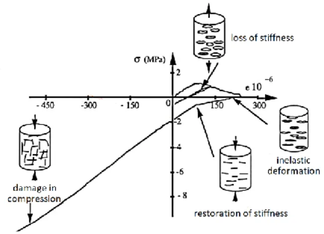
Within the family of damage models, we have chosen the Fichant-La Borderie (FLB) model because of its innate ability to capture the following mechanically induced phenomena that are illustrated in Figure 1: the initial elastic properties of concrete; the degradation of stiffness due to micro-cracking and damage evolution; the large asymmetry between compressive and tensile behaviour; the partial restoration of stiffness in compression due to crack closure, i.e. the unilateral effect. By coupling the FLB model to a LITS model, it would be possible to capture the development of LITS in the case of transient thermal loads and compressive stress states in addition to the mechanically induced phenomena.
Figure 1. Effect of damage on anisotropic concrete stiffness, reproduced from Ramtani (1990). The concept of damage mechanics was developed in the 1950’s, and quite simply allowed the estimation of the stiffness of “damaged” volumes via introducing a damage scalar variable, D. This is shown by Equation 1, where 𝑆0 and 𝑆𝐷 are respectively the initial and damaged surfaces in an initial volume, and E and 𝐸̃ are the initial and effective stiffness. This can be manipulated to form Equation 2, where the constitutive response of an isotropic damaged material is calculated from the effective stress tensor, 𝜎̃𝑖𝑗,
which is calculated from the undamaged materials stress tensor (𝜎𝑖𝑗) and the damage scalar (𝐷).
𝐷 = 𝛿𝑆𝐷 𝛿𝑆0 = 1 − 𝐸̃ 𝐸 (1) 𝜎̃𝑖𝑗 = 𝜎𝑖𝑗 1−𝐷 (2)
Since its inception, the damage model proposed by Mazars (1986) has become an industry workhorse for concrete. However, this isotropic local damage model cannot be used for inelastic strains, nor can it capture the unilateral effect; this is particularly important in compressive states occurring after tensile damage. e.g. during Mode I crack opening. Other models have also been developed which allow the unilateral effect, however, they assume non-linear elasticity, thus making them incompatible for capturing LITS. The FLB model is an extension of the Mazars model, which simplifies the number of input parameters defining the tensile and compressive asymmetry. The FLB model formalism makes it easy to introduce an energy-based regularisation method of the Hillberborg type. Thus, minimising mesh dependency in a finite element implementation; this is a technique suited to local damage models. Moreover, the method decomposes elastic and inelastic contributions to damage, hence, is suitable for capturing the inelastic LITS contribution to stiffness degradation.
25 Conference on Structural Mechanics in Reactor Technology Charlotte, NC, USA, August 4-9, 2019 Division I In this paper, a method for utilising the FLB approach for modelling the component of damage due to LITS is proposed. The first results towards a robust and reliable coupling of LITS and appropriate damage model are presented. The constitutive behaviour laws are developed in the open source MFront software (2015), which is a cross-platform constitutive modelling environment that is compatible with a range of commercial and open source finite element software.
NUMERICAL MODELLING APPROACH LITS model definition
Torelli et al. (2017) describe the confinement dependent LITS model, which allows the modification of LITS due to a stress triaxiality index. This method was developed because of the body of experimental evidence that shows that LITS is dependent on stress confinement rather than the traditional assumption of superposition of the individual uniaxial stress states. Total strains are assumed to be a superposition of the elastic strains, free thermal strains, and the remainder being due to LITS, i.e. Δ𝜀𝑇𝑜𝑡= Δ𝜀𝐸𝑙+ Δ𝜀𝐹𝑇𝑆+
Δ𝜀𝑙𝑖𝑡𝑠. 𝜀̇𝑖𝑗𝑙𝑖𝑡𝑠= 𝜂𝛽(𝑇) 𝜎𝑢0[−𝜐𝑙𝑖𝑡𝑠𝜎𝑘𝑘 −𝛿 𝑖𝑗+ (1 − 𝜐𝑙𝑖𝑡𝑠)𝜎𝑖𝑗−]𝑇̇ (3) 𝜂 = 1 + (𝐶𝑚− 1)𝛾 (4) 𝐶𝑚 = |𝜎1−+𝜎2−+𝜎3−| √(𝜎1−)2+(𝜎 2−)2+(𝜎3−)2 (5) 𝛽(𝑇) = 𝑏0+ 𝑏1𝑇 + 𝑏2𝑇2+ 𝑏3𝑇3+ 𝑏4𝑇4 (6)
The LITS model is described by Equations 3-6, which is a traditional implementation of LITS behaviour modified to account for confinement dependence. η is the stress triaxiality function and γ is a material parameter calibrated to experimental data for the appropriate temperature range. 𝐶𝑚 is the
triaxiality index linked to the principal stresses, and β(T) is a polynomial function describing uniaxial temperature-LITS behaviour observed in the literature. 𝜎𝑢0 is the compressive strength of the material, 𝜎𝑖𝑗−
is the (i,j)th component of the negative projection of the stress tensor and 𝜐
𝑙𝑖𝑡𝑠 is a material parameter
analogous to the elastic Poisson’s ratio. The LITS model described here has previously been implemented in the open-source software MFront and is utilised in this study as the basis of the coupled LITS-FLB damage approach; this initial implementation is available in the MFrontGallery project1.
FLB model definition
As described by Fichant et al. (1999), the FLB model is utilised as a starting point for capturing inelastic sources of damage in concrete. The FLB damage scalar (Equation 7) is similar to Equation 1 but based on the assumption that the stiffness decreases exponentially and is thereby prevented from reaching 0, thus avoiding convergence issues. 𝜀𝑑0=𝑓𝑡⁄ is the strain at the onset of damage and 𝜀𝐸 𝑒𝑞 is the equivalent
inelastic strain defined by Mazars in Equation 8, which implies compatibility with LITS. 𝐷 = 1 − 𝜀𝑑0 𝜀𝑒𝑞𝑒𝑥𝑝{𝐵𝑡(𝜀𝑑0− 𝜀𝑒𝑞)} (7) 𝜀𝑒𝑞= √∑3𝑖=1〈𝜀𝑖𝑒〉2 (8) 𝐵𝑡 = 𝑓𝑡ℎ 𝐺𝑡−0.5𝜀𝑑0ℎ𝑓𝑡 (9) 𝜎𝑖𝑗= (1 − 𝐷)〈𝜎̃𝑖𝑗〉++ (1 − 𝐷𝛼)〈𝜎̃𝑖𝑗〉− (10)
1 https://github.com/thelfer/MFrontGallery/tree/master/generic-behaviours/viscoplasticity
The unilateral effect is accounted for via Equation 9, where 𝐵𝑡 is the damage parameter analogous
to the basic Mazars model, which features the energy regularisation method where 𝑓𝑡, 𝐺𝑡, and h are the
fracture tensile strength, fracture energy, and characteristic element length respectively. The total stress is defined via Equation 10 in terms of the damage scalar and the decomposed effective stress tensor for tensile and compressive behaviour; α is a material parameter linked to damage in the compressive state that can be calibrated to a particular composition of concrete. It should be noted that the FLB parameters are physically meaningful and can be characterised from experiments, which makes it simpler to calibrate than the Mazars model it is based upon.
Unlike the LITS model, the FLB model is available as a native law in the open source Cast3M software2. In order to couple with the LITS model implemented in MFront, first a standalone FLB model
was implemented in MFront. This implementation was verified against the Cast3M implementation on various test cases. Whilst not shown here, this proved that the MFront implementation was correct and numerically efficient. The MFront implementation of FLB was then used in EDF open-source finite element solver Code_Aster3 on the same test cases, proving the portabilitity of the MFront implementation. This
FLB model was used in conjunction with the LITS model as the basis of the present study. The benefit of implementation within MFront is clearly demonstrated as the behaviour laws are compatible for use with a range of open source and commercial FE packages, thus improving numerical verification, which is important for industry.
Within this paper, the FLB description here was utilised in conjunction with the FLB model to implement a decoupled LITS-Damage model. This is simply a LITS behavior law, with a damage calculation performed from the FLB description by way of post-processing. Hence, it means that the LITS-damage model is essentially a LITS model with no influence of LITS-damage – the LITS-damage field is calculated as if it were taking part in the behaviour.
Coupled LITS and FLB model definition
The coupled inelastic FLB and thermoelastic LITS model are integrated using an implicit 𝜃-sheme. A priori, the unknowns are the increments of: the elastic strain 𝛥 𝜀̲el; the LITS strain 𝛥 𝜀̲vp; damage 𝛥 𝑑. As discussed in the following, the increment of damage 𝛥 𝑑 can be eliminated from the implicit system. Thus, one has to define two tensorial equations, respectively associated with the elastic strain and the LITS strain that the increments 𝛥 𝜀̲el and 𝛥 𝜀̲vp must satisfy. Equations 11-14 define the implicit system to be solved, where 𝛥 𝑡 is the time increment.
𝑓𝜀̲el(𝛥 𝜀̲el, 𝛥 𝜀̲vp) = 0 (11)
𝑓𝜀̲vp(𝛥 𝜀̲el, 𝛥 𝜀̲vp) = 0 (12)
𝑓𝜀̲el = 𝛥 𝜀̲el+ 𝛥 𝜀̲vp− 𝛥 𝜀̲to (13) 𝑓𝜀̲vp= 𝛥 𝜀̲vp− 𝛥𝑡 𝑓LITS(𝜎̲|𝑡+𝜃 𝛥 𝑡) (14) The FLB damage model introduces an explicit relation between the stress and the elastic strain 𝜀̲el and the damage 𝑑 through Equation 15-17. In FLB, the damage evolution 𝛥 𝑑 can be explicitly computed as a function of the elastic strain increment 𝛥 𝜀̲el. This means that 𝜎̲|𝑡+𝜃 𝛥 𝑡 can be written as a function of
𝛥 𝜀̲el only, following Equation 18.
𝜎̲|𝑡+𝜃 𝛥 𝑡= 𝑓FLB(𝜀̲el|𝑡+𝜃 𝛥 𝑡, 𝑑|𝑡+𝜃 𝛥 𝑡) (15) 𝜀̲el| 𝑡+𝜃 𝛥 𝑡= 𝜀̲ el| 𝑡+ 𝜃 𝛥 𝜀̲ el (16) 𝑑|𝑡+𝜃 𝛥 𝑡= 𝑑|𝑡+ 𝜃 𝛥 𝑑 (17)
2 http://www-cast3m.cea.fr/ 3 https://www.code-aster.org/
25 Conference on Structural Mechanics in Reactor Technology Charlotte, NC, USA, August 4-9, 2019 Division I 𝜎̲|𝑡+𝜃 𝛥 𝑡= 𝑓FLB(𝜀̲el|𝑡+𝜃 𝛥 𝑡, 𝑑|𝑡+𝜃 𝛥 𝑡(𝛥 𝜀̲el)) (18)
The implicit system is solved by a standard Newton algorithm, which requires its Jacobian matrix, J, to be computed (Equation 19). 𝐽 can be decomposed by blocks, where 𝜕𝑓𝜀̲el
𝜕𝛥 𝜀̲el, 𝜕𝑓 𝜀̲el 𝜕𝛥 𝜀̲vp and 𝜕𝑓𝜀̲vp 𝜕𝛥 𝜀̲el are the identity. Computation of 𝜕𝑓𝜀̲vp
𝜕𝛥 𝜀̲vp is more demanding since the derivative of the eigentensors of tensors must be computed. A symbolic expression of 𝜕𝑓𝜀̲vp
𝜕𝛥 𝜀̲vp is given by Equation 20, using the relation
d𝜀̲el|𝑡+𝜃 𝛥 𝑡
d𝛥 𝜀̲el = 𝜃 𝐈̲̲. Whilst MFront provides all the tools to compute those partial derivatives, another strategy is to let 𝜕𝑓𝜀̲vp 𝜕𝛥 𝜀̲vp be computed numerically 4. 𝐽 = ( 𝜕𝑓 𝜀̲el 𝜕𝛥 𝜀̲el 𝜕𝑓 𝜀̲el 𝜕𝛥 𝜀̲vp 𝜕𝑓𝜀̲vp 𝜕𝛥 𝜀̲el 𝜕𝑓𝜀̲vp 𝜕𝛥 𝜀̲vp ) (19) 𝜕𝑓𝜀̲vp 𝜕𝛥 𝜀̲el = −𝛥𝑡 d𝑓LITS d𝜎̲|𝑡+𝜃 𝛥 𝑡 . d𝜎̲|𝑡+𝜃 𝛥 𝑡 d𝛥 𝜀̲el = −𝛥𝑡 d𝑓LITS d𝜎̲|𝑡+𝜃 𝛥 𝑡 . ( 𝜕𝜎̲|𝑡+𝜃 𝛥 𝑡 𝜕𝜀̲el| 𝑡+𝜃 𝛥 𝑡 d𝜀̲ el| 𝑡+𝜃 𝛥 𝑡 d𝛥 𝜀̲el + 𝜕𝜎̲|𝑡+𝜃 𝛥 𝑡 𝜕𝑑|𝑡+𝜃 𝛥 𝑡 d𝑑|𝑡+𝜃 𝛥 𝑡 d𝜀̲el| 𝑡+𝜃 𝛥 𝑡 d𝜀̲ el| 𝑡+𝜃 𝛥 𝑡 d𝛥 𝜀̲el ) = −𝜃 𝛥𝑡 d𝑓LITS d𝜎̲|𝑡+𝜃 𝛥 𝑡 . ( 𝜕𝜎̲|𝑡+𝜃 𝛥 𝑡 𝜕𝜀̲el| 𝑡+𝜃 𝛥 𝑡 +𝜕𝜎̲|𝑡+𝜃 𝛥 𝑡 𝜕𝑑|𝑡+𝜃 𝛥 𝑡 d𝑑|𝑡+𝜃 𝛥 𝑡 d𝜀̲el| 𝑡+𝜃 𝛥 𝑡 ) (20)
Finite element model definition
A representative volume model is set up as illustrated by Figure 2; it is a plane strain model of a centrally cracked brick. The geometry of the of the square plate is 100x100mm with a 20mm crack. The geometry is meshed with regular 4-node linear elements; mesh size is 2.5mm unless specified otherwise. The boundary conditions on the nodes of the base of the volume are assigned dy=0, a single node at the origin is also assigned dx=0 to remove rigid body motion, and the nodes on the top edge are assigned prescribed displacement evolution in the y-axis up to ±0.03mm, as shown in Figure 2.
Figure 2. Model of double edge cracked brick with boundary conditions sets BC-1, BC-2, and displacements described. BC-1 is applied during heating phase to specifically force the evolution of LITS
before applying BC-2 during the constant temperature phase to evoke mechanical deformation. The boundary conditions have been chosen to evoke the evolution of deformation due to LITS during 0<𝑡≤100, the evolution of deformation in tension during 100<𝑡≤300, and the evolution of
4 This is available since Version 3.1 thanks to the @NumericallyComputedJacobianBlocks keyword.
deformation in compression during 300<𝑡≤500. This is to demonstrate appreciable differences in both stress state and damage evolution when different constitutive behaviours are employed.
The Newton method is used to compute the residual; an initial prediction is made using the tangent matrix but in subsequent iterations the tangent matrix is used in order to enhance convergence rate, re-computing every third iteration. To aid convergence for non-linear problems involving damage, the linear research method is employed utilising a uni-dimensional secant method, i.e. a functional minimisation algorithm. A relative residual of 1E-6 is used as a convergence criterion with a limit of 100 iterations. Time step cutting is employed, sub-dividing by 2, which is allowed up to 20 times.
RESULTS
The models were run in code_aster finite element software for four cases, differing only by material behaviour: pure elastic; LITS standalone; FLB standalone; uncoupled LITS-Damage; coupled LITS-FLB. For clarity, the elastic model denotes the case where a only elastic properties are assumed with no ability to compute damage. The LITS model denotes the case where the thermoelastic LITS constitutive behaviour is assumed with no ability to compute damage. The FLB model denotes the case where the inelastic damage constitutive behaviour law is assumed. The LITS-Damage model denotes the case where the thermoelastic LITS constitutive behaviour is assumed, with a non-intrusive (uncoupled) post-processing of damage evolution using underlying FLB equations. In other words, LITS is driving the constitutive response, and damage is computed as if the behaviour was FLB, i.e. D is not influencing the constitutive behaviour. The LITS-FLB model denotes the case where the inelastic damage law is described by the coupled LITS-FLB laws. Here the LITS behaviour is modified by the FLB damage evolution, i.e. D is influencing the constitutive behaviour.
Evolution of total stress fields in y-direction
Figure 3 shows the macro stress and strain response averaged over the whole cracked plate. The elastic model shows the reference response of the plate, which is linear during thermal and mechanical loading.
Figure 3. Averaged 𝜎𝑦𝑦 over the element and averaged 𝜀𝑦𝑦 over the element plotted as history traces.
These figures show the macro deformation response of the cracked plate.
The FLB model correlates closely with the elastic case through thermal loading (t=100s). During mechanical loading it shows a reduction stress magnitude near both the peak tensile (t=200s) and compressive (t=400s) conditions, indicating mechanical damage evolution. Note that the FLB model also shows stiffness restoration during compressive phase. In contrast, the LITS model shows a reduced stress magnitude in the heating phase compared to elastic conditions, which is expected from the development of
25 Conference on Structural Mechanics in Reactor Technology Charlotte, NC, USA, August 4-9, 2019 Division I LITS in the direction of load. During the mechanical loading phase, the behaviour continues as elastic. In the tensile phase, the peak stress carried is higher than the elastic case. Since the deformation of the plate is prescribed, and the same in all cases, the resultant stress magnitude is the stress at the end of tensile loading (t=200s) compensated by the stress at the end of heating phase (t=100s). This difference in stress compared to the elastic case is due to the evolution of LITS and is maintained throughout the compressive phase. At this stage, suffice to say that the FLB model cannot capture LITS effects and the LITS model cannot capture mechanical damage effects.
As described previously, the uncoupled LITS-Damage model is effectively the same as the LITS model, hence, identical the stress and strain histories are produced. The coupled LITS-FLB behaviour is shown to lie in between the purely elastic and the LITS cases. The stress closely correlates with the LITS behaviour during the heating phase. Partway through the tensile loading phase, there is a sudden departure from elasticity (t≈150s) indicating the onset of damage. Stiffness recovery is captured in the compressive stage with a reduction in stress magnitude at peak compressive loading, indicating further damage evolution. At this stage suffice to say the coupled LITS-FLB model has captured both LITS effects and mechanical damage at a macro scale.
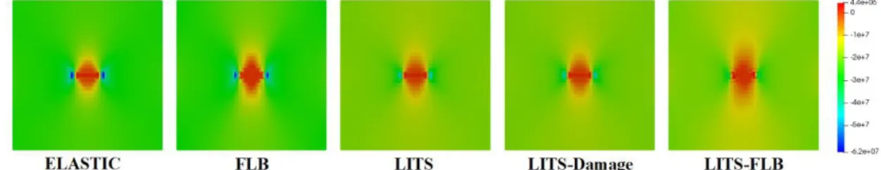
Figure 4. 𝜎𝑦𝑦 in the plate after thermal loading stage (t=100s). Comparison of elastic behaviour in
isolation, FLB in isolation, LITS in isolation, uncoupled LITS-Damage, and coupled LITS-FLB. More detail about the response is observed from the stress fields. When t=100s, the boundary conditions of the cracked plate have induced restrained thermal expansion, thereby activating LITS. Figure 4 shows that the magnitude of the compressive stress state is predicted to be greatest when assuming elastic conditions and that a similar distribution is observed when assuming FLB behaviour. This is expected as LITS phenomena is not captured, thus, inelastic unloading is neglected by the elastic and FLB model. In contrast, the LITS only, uncoupled LITS-Damage and the coupled LITS-FLB show a reduction in the magnitude of the compressive stress state. The uncoupled LITS-Damage constitutive model is not affected by the FLB law, thus, the predicted stress states are identical to the LITS only model. In contrast, the coupled LITS-FLB model shows a smaller reduction in compressive stress state, lying in between the elastic and FLB models and the LITS only models.
Figure 5. 𝜎𝑦𝑦 in the element at the peak tensile loading stage (t=200s). Comparison of elastic behaviour in isolation, FLB in isolation, LITS in isolation, uncoupled LITS-Damage, and coupled LITS-FLB.
When 100s<t<200s, the boundary conditions evoke tensile deformation only. At t=200, one would expect the stress state in the plate to change from compressive at the end of heating to tensile at the peak of tensile loading. Figure 5 shows this is generally true but a range of phenomena are occurring and captured
by the different models. The LITS and uncoupled LITS-Damage model show the highest stress magnitudes in comparison to the elastic case, whereas the FLB and coupled LITS-FLB models show reduced stress magnitudes, indicating tensile damage. Considering that the imposed tensile deformation gradually reduces the compressive stresses at the end of the heating phase leading to the appearance of tensile stresses at
t=200s. Simply put, for the former models, the overall tensile stresses are higher at t=200s as the
compressive stresses at t=100s are lower than the elastic case. Whereas for the latter models, the reduction in stress state compared to the elastic case indicates significant damage evolution (correlating with Figure 7). The damage to the cracked plate means that the plate cannot support the same magnitude of tensile stress as the undamaged case, i.e. elastic, LITS, and uncoupled LITS-Damage.
Figure 6. 𝜎𝑦𝑦 in the element at the peak compressive loading stage (t=400s). Comparison of elastic behaviour in isolation, FLB in isolation, LITS in isolation, uncoupled Damage, and coupled
LITS-FLB.
When 200s<t<300s, the plate unloads and when 300s<t<400s the boundary conditions evoke compressive deformation. At t=400, it would be expected that the stress state in the overall volume changes from tensile and into compression at the peak of compressive loading; no further evolution of deformation due to LITS is expected as there is no change in temperature. Figure 6 shows that this is generally true and for all assessed models the area around the notch stays in tension. However, the elastic and FLB only models indicate high local compressive stresses occurs at the front notch, whereas LITS based models show lower compressive states. This is important in terms of fracture mechanics assessments, as neglecting LITS can lead to additional conservatism; high crack tip constraint would increase propensity of a crack to propagate under a given load.
Evolution of damage fields
Note that for the elastic model and for the LITS only model, no damage is predicted, hence, the trivial solutions of 0 damage are omitted. During the thermal loading phase (t<100s), it is clear that two types of damage can occur (Figure 7): mechanical damage in compression (captured by FLB); damage due to evolution of thermal phenomena, i.e. LITS including thermal expansion. In the case of LITS models, the stress relief in the whole plate due to LITS evolution is significant and there are very low levels of damage predicted to evolve within the plate during the heating phase. However, damage is confined locally around the crack. This is a reasonable prediction, as the crack tip is generally the site of further degradation. The damage prediction in the LITS models manifest as localised hot spots with similar magnitude to that predicted by FLB alone.
25 Conference on Structural Mechanics in Reactor Technology Charlotte, NC, USA, August 4-9, 2019 Division I
Figure 7. Damage distribution in the element at the end of the thermal loading stage (t=100s). Comparison of FLB in isolation, uncoupled LITS-Damage, and coupled LITS-FLB .
During the tensile loading phase, damage evolution in all cases is significant. Figure 8 shows that for the FLB and uncoupled LITS-Damage the mechanical damage in tension is of similar order of magnitude, but with significantly different damage patterns, which is due to the different damage distributions at the start of the tensile phase. The coupled LITS-FLB model shows that an aggregated superposition of the two damage fields has occurred, leading to significant damage along the expected crack path in the centre of the plate during the heating phase. This is sensible as the coupled LITS-FLB model manifested to significant damage hotspots at the end of the heating phase. When combined with the tensile loading, the formation of a high degree of damage equivalent to complete rupture of the plate is predicted.
Figure 8. Damage distribution in the element at the peak tensile loading stage (t=200s). Comparison of FLB in isolation, uncoupled LITS-Damage, and coupled LITS-FLB.
During the compressive loading phase, all models show that additional damage is sustained, as shown in Figure 9. This is due to the restoration effect from crack closure in compression is captured by the modes. As the FLB and uncoupled LITS-Damage models had lower damage levels, there is increase in damage fields. Again, the damage fields show the different distributions that were observed in tensile phase. The coupled LITS-FLB model shows the combination of typical damage in tension (where cracks appears perpendicularly to the load) and further damage from the restoration in compression.
Figure 9. Damage distribution in the element at the peak compressive loading stage (t=400s). Comparison of FLB in isolation, uncoupled LITS-Damage, and coupled LITS-FLB.
CONCLUSIONS
An approach for coupling LITS with FLB damage has been proposed and discussed. The implementation of this has been demonstrated and is a promising approach for capturing both the effects of mechanical damage and LITS evolution in concrete. Indeed, coupling the LITS and FLB damage law results in significantly different damages fields from the FLB standalone (with no LITS history) and LITS de-coupled damage (with no damaged stress tensor history).
The coupling enables a prediction that characterises crack evolution coming from the different types of loading including mechanical, thermal, and LITS. This novel coupling has shown that it may be important to take into account the LITS phenomena in order to successfully model the damage evolution of the concrete under temperature and constraint.
At this stage, analysis of the model results and their relation to the physical mechanisms governing degradation are ongoing but are indicative of the relative importance of the LITS phenomena in specific cases. It is reasonable to infer that the coupled LITS-FLB model could give more physically representative descriptions of the evolution of cracks in concrete, especially in comparison to damage based models which do not account for LITS, e.g. Mazars. The application of coupled LITS-FLB could lead to a reduction in conservatism for industrial assessments, such as fracture assessments.
Further numerical testing is required in order to ensure the coupled LITS-FLB model is robust under all conditions. Moreover, it would be beneficial to incorporate a broad range of experimental testing in order to validate the predictive capabilities of the models. The FLB model and the coupled LITS-FLB model will be available to use with a range of FE software once integrated in the MFront source code. Development through the non-intrusive MFront software ensures fast and robust deployment of behaviour laws to a range of different FE packages.
ACKNOWLEDGMENTS
The authors would like to acknowledge the support of Gerd-Jan Schreppers and associates of TNO, Delft, for their invaluable support and advice during this project.
REFERENCES
Torelli, G., Mandal, P., Gillie, M. and Tran, V.X. (2016). “Concrete strains under transient thermal conditions: a state-of-the-art review,” Engineering Structures, 127 172-188
Torelli, G., Gillie, M., Mandal, P. and Tran, V.X. (2017). “A multiaxial load-induced thermal strain constitutive model for,” International Journal of Solids and Structures, 108 115-125
Torelli, G., Mandal, P., Gillie, M. and Tran, V.X. (2018). “A confinement-dependent load induced thermal strain constitutive model for concrete subjected to temperatures up to 500oC,” International Journal
of Mechanical Sciences, 144 887-896
Mazars, J. (1986). “A description of micro- and macro scale damage of concrete structures,” Engineering
Fracture Mechanics, 25 729-737
Fichant, S., La Borderie, C. and Pijauder-Cabot, G. (1999). “Isotropic and anisotropic descriptions of damage in concrete structures,” Mechanics of Cohesive-Frictional Materials, 4 339-359
Ramtani, S. (1990). “Contribution à la modélisation du comportement multiaxial du béton endommagé avec description du caractère unilateral,” Thesis, Paris 6. 9, 11, 35
Helfer, T., Michel, B., Proix, J.-M., Salvo, M., Sercombe, J., and Casella, M. (2015). “Introducing the open-source mfront code generator: Application to mechanical behaviours and material knowledge management within the PLEIADES fuel element modelling platform”. 70(5):994–1023.