HAL Id: hal-01181267
https://hal.archives-ouvertes.fr/hal-01181267
Submitted on 29 Jul 2015
HAL is a multi-disciplinary open access
archive for the deposit and dissemination of
sci-entific research documents, whether they are
pub-lished or not. The documents may come from
teaching and research institutions in France or
abroad, or from public or private research centers.
L’archive ouverte pluridisciplinaire HAL, est
destinée au dépôt et à la diffusion de documents
scientifiques de niveau recherche, publiés ou non,
émanant des établissements d’enseignement et de
recherche français ou étrangers, des laboratoires
publics ou privés.
Performance enhancement of a closed-loop
accelerometer tuned close to its instability regime
Anton Korniienko, E Colinet, Cyril Condemine
To cite this version:
Anton Korniienko, E Colinet, Cyril Condemine. Performance enhancement of a closed-loop
accelerom-eter tuned close to its instability regime. 2009 IEEE NEWCAS-TAISA, Jun 2009, Toulouse, France.
pp.1 - 4, �10.1109/NEWCAS.2009.5290485�. �hal-01181267�
Performance enhancement of a closed-loop accelerometer tuned close
to its instability regime
A. Korniienko, E. Colinet, and C. Condemine
CEA, LETI, MINATEC, 17 rue des martyrs, 38054 Grenoble Cedex 9, France
Contact author : [email protected]
Abstract - A closed-loop micro-accelerometer is presented where its instability regime is used in order to enhance its static gain.
Sensitivity functions are decreased in low frequencies and therefore any acceleration applied on the proof mass is better rejected than in conventional closed-loop approach. To design a robust controller, an identification procedure of the instable structure is presented as well. Finally the signal reconstruction of the applied acceleration is made trough a Kalman filter. Simulation results are given and demonstrate the efficiency of the proposed approach.
I. INTRODUCTION
Capacitive micro-electro-mechanical accelerometers are since few years now, commonly used in various fields, e.g. in the automotive domain for airbag application, in the biomedical domain for pacemaker, in navigation system [1-2]. Most of these accelerometers are used in open-loop because of simplicity of implementation, robustness, consumption and cost. However overall performance is not as good as closed loop approach in terms of linearity, dynamic range, and bandwidth [3]. In [4], such closed-loop accelerometer has been presented and shows some great performance compared to state of the art. As an extension to this work, this article presents an original approach to enhance even more the system performance using the accelerometer in its instability regime. In this regime, the accelerometer static gain is much higher allowing a better error rejection. Furthermore, to reconstruct as well as possible the measured acceleration, a Kalman filter is used. The first part of the article presents the mechanical structure and its associated model. Next, we will show how the instability regime can be positively exploited. Finally, some simulation results are presented and compared to previous approaches.
II.ACCELEROMETER DESCRIPTION
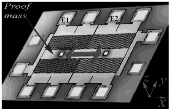
Figure 1 shows a photograph of the capacitive micro-accelerometer. It is made of a proof mass sensitive in the (Ox) direction associated with comb electrodes E1 and E2 used for electrostatic actuation and capacitive detection. The mass dynamic can be modeled as follows:
)
(
)
(
)
(
)
(
)
(
t
b
0x
t
k
x
t
ma
t
F
t
x
m
mec
fb (1)where m is the mass, b0 its damping factor, kmec its stiffness, a(t) the external acceleration to be measured which is considered here
as a perturbation to be rejected and Ffb is the feedback electrostatic force used to maintain the mass in its equilibrium position.
E1 E2
r=0 controller K Accelerometer H V F actuation V F actuation External accelerationa(t) X V detection x + -(t)
Kalman filter Estimated accelerationâ(t) + -u y Fig. 2. Schematic of the considered closed-loop system
The detection of the mass displacement is made thanks to the capacitance variation Cmes which can be expressed in small
displacement (g>>x):
)
(
)
(
)
(
)
(
0 02t
x
g
S
t
C
t
x
g
S
t
C
mes
mes
(2)where 0 is the air permittivity, S the electrode area, g the capacitance nominal gap when x=0
In order to convert the capacitance variation in the digital domain, the time varying capacitance Cmes is embedded in a sigma-delta
ADC so that one may write for the detection block:
)
(
)
(
t
K
x
t
y
d (3)where Kd is the equivalent detection gain and y(t) is the controller input.
Since the displacement of the proof mass is transposed in the digital domain, one may build a digital controller fully programmable so that the delivered feedback forces Ffb can compensate the acceleration force. Figure 2 shows a schematic of the
considered closed loop system. The feedback force uses the electrostatic actuation of the mass which can be expressed as follows supposing that g>>x:
x
g
SV
g
SV
x
g
SV
F
fb fb fb 3 fb 2 0 2 2 0 2 2 02
1
)
(
2
1
(4)where Vfb is the voltage command delivered by the controller. To preserve the actuator linearity linked to the square term in (4),
the voltage Vfb is encoded into a 1 bit signal thanks to a sigma-delta modulator and according to the sign of Vfb the signal is
injected to the appropriate electrode E1 or E2 to have a positive or negative force. One may then write:
)
(
)
(
)
(
t
K
u
t
k
x
t
F
fb
a
elec (5)where Ka is the actuation gain, u(t) the feedback command delivered by the controller, and
k
electhe positive equivalentelectrostatic stiffness function of the feedback voltage Vfb [5]:
3 2 0
g
SV
k
elec
fb (6)More details regarding the practical implementation of the entire system can be found in [4][6].
Finally, the linearized dynamical equation of the proof mass can be expressed in the Laplace domain as follows:
elec mec a d
k
k
p
b
mp
K
K
U
Y
p
H
0 2)
(
(7)Fig.3. Effect of the electrostatic stiffness kelec on the open loop system transfer function H(p) while applying different Vfb voltages.
III.CLOSED-LOOP DESIGN
A. Instability regime
From equation 6, one may notice that increasing the feedback voltage Vfb increases the electrostatic stiffness magnitude. Since
this coefficient is strictly positive, it compensates the mechanical stiffness kmec of the proof mass and therefore enhances the gain
of the transfer function H(p) in low frequencies:
elec mec
k
k
p
H
p
1
)
(
lim
0 (8)When
k
mec
k
elec , the sensor is settled in its instability regime. Figure 3 illustrates this phenomenon. A high static gain ofH(p) decreases the sensitivities functions S and KS magnitude in the accelerometer bandwidth [7-8]. These functions represent
respectively the influence of the acceleration at on the closed-loop measurement error (t) and the contribution of the process
measurement noise b(t) on the controller output y(t). Thus, the reduction of the sensitivities functions magnitudes in the sensor bandwidth enhances the performance of the closed-loop sensor.
B. System identification and controller design
To increase the accelerometer performance, the system must work close to its instable regime. This induces some problems. The system identification cannot be realized without a controller that stabilizes the loop. Moreover, several steps (identification and controller synthesis) are needed to reach the feedback actuation voltage Vfb critical value1.
To solve these problems, the following algorithm is proposed:
a) using the synthesized controller, one must increase Vfb to the stability limit of the closed loop;
b) the identification of the process H(p) is then realized in the closed-loop regime; c) a controller is synthesized having more stability margin than the previous one; d) repeating steps a) – c) until obtaining the feedback actuation voltage critical value.
The controller is synthesized using the Hinf method [9] with weighting filters on the sensitivities functions so that it stabilizes the loop and ensures the following condition:
P
(
p
),
K
(
p
)
1
F
l (9)where
F
l
P
(
p
),
K
(
p
)
is the fractional linear transformation which relates the system inputs to its outputs,
is the Hinfstandard norm.
C. Observator design
1
The critical value of the feedback voltage Vfb is defined when kmec kelec
Vfb Identified model with Vfb=3.8VIdentified model with Vfb=3.7V
Finally, to eliminate possible measurement noises and non-linear distortions, the acceleration signal is reconstructed using a classical Kalman filter technique. The acceleration signal a is modeled as a constant disturbed by a gaussian zero centered white noise source vk with variance Va
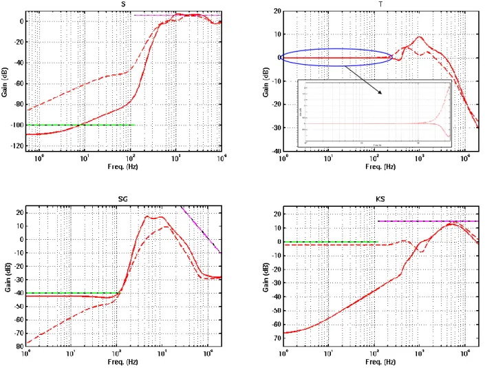
Fig. 4. Sensitivity functions (S=(1+KH)-1, T=KH(1+KH)-1, SG=H(1+KH)-1, KS=K(1+KH)-1) of the closed loop system with the optimal feedback voltage Vfb=3.8 Volt (full line) compared to the nominal close loop system Vfb=2.5Volt (dashed line).
Requirements are presented by coloured (green and purple) straight lines
k k
k
a
v
a
1
(10)The variance Va is a fitting parameter which represents the degree of confidence in the knowledge of the acceleration signal. The higher the value Va is, the quicker we authorize the acceleration signal to evolve in a short amount of time. On the contrary, a small variance Va models an acceleration that does not change abruptly. Thus, having the models of the accelerometer, its noise and the acceleration signal, one may build an extended model of the whole system following the same procedure as in [10]. For this model, a Kalman filter can be constructed so that the system state vector including acceleration signal can be estimated.
IV.SIMULATION RESULTS
In order to evaluate the efficiency of the proposed approach, some Matlab/Simulink simulations have been performed. After few iterations of the algorithm presented in section 3.2, an optimal controller is obtained where the optimal value of the actuation feedback voltage Vfb is around 3.8 Volt and standard Hinf norm . The corresponding sensitivity functions are presented in Figure 4 and compared to the case where Vfb=2.5 Volt. As expected, the sensitivity functions S=(1+KH)-1 and KS magnitude are smaller in low frequencies (accelerometer bandwidth is 122Hz) than the ones obtained in the nominal regime (in dashes). Therefore, better dynamic error compensation is attained. Finally, Figure 5 shows simulation results while using the extended Kalman filter in the unstable regime to reconstruct the acceleration â(t). Table 1 summarizes performance obtained in nominal and near-instable regime.
V.CONCLUSION
This paper has demonstrated the advantages of the instable operation regime for a capacitive micro-accelerometer. It emphasizes the difficulties to design a controller in this operation mode and proposed a solution to circumvent them. Moreover, a Kalman reconstruction filter was used to estimate properly the acceleration signal. Simulations in Matlab/Simulink were presented to illustrate the viability of the approach. We achieved 20 bits resolution instead of 17.5 bits in the nominal regime.
Fig. 5. Simulation results of the acceleration reconstruction through a Kalman filter. From top to down: power spectral density of the applied acceleration (black), power spectral density of the dynamical error (t) in the nominal regime (red), power spectral
density of the acceleration reconstruction error in the nominal regime (pink) and in the instable regime (blue)
REFERENCES
[1] Kraft, M., “Micromachined inertial sensors: The state of art and a look into the future”. IMC Measurement and Control, 33(6), pp. 164-168, 2000.
[2] Yazdi, et al., “Micromachined inertial sensors”, Proceedings of the IEEE, 86(8), pp. 1640–1658, 1998.
[3] Chau, K. H.-L., et al., “An integrated force-balanced capacitive accelerometer for low-g applications”, Sensors and Actuators A, 54, pp. 472–476, 1996.
[4] J. Soen, et al., “Controller design for a closed-loop micromachined accelerometer”, Control Engineering Practicen vol 15, no. 1, pp. 57–68, 2007.
[5] Handtmann, et al., “Sensitivity enhancement of MEMS inertial sensors using negative springs and active control”, Sensors and Actuators A, pp. 97–98, 153–160, 2002.
[6] Condemine, C., et al., “A 0.8mA 50 Hz 15b SNDR SD closed-loop 10g accelerometer using an 8th-order digital compensator” Proceedings of the 2005 IEEE international solid-state circuits conference, San Francisco, vol. 13, pp. 248–249, 2005.
[7] Skogestad, S., et al., “Multivariable feedback control: Analysis and design”. New York: Wiley, 1996. [8] Landau, I. D., “System identification and control design.”, Englewood Cliffs, NJ: Prentice-Hall Inc, 1990. [9] Doyle, J. C., et al., “Feedback control theory”. Maxwell Macmillan Intern. Editions, 1992.
[10] E. Colinet, et al. “Resolution enhancement of a sigma-delta micro-accelerometer using signal prediction”, Proceedings of the International Conference on MEMS, NANO and Smart Systems (ICMENS’04), pp. 409–413, 2004.
TABLE I
SYSTEM OVERALL PERFORMANCE IN NOMINAL AND NEAR INSTABLE REGIME
Nominal regime with Vfb=2.5 Volt Near instable regime with Vfb=3.8 Volt Fsampling 250000 Hz 250000 Hz Number of samples 1250000 1250000 Bandwidth 122 Hz 122 Hz
Fundamental 0.77peak@20Hz 0.77peak@20Hz
Rms Noise -110.5 dB -126.2 dB
Equivalent resolution 17.5 bits 20.1 bits
S/N 105.2 dB 120.9 dB
THD -114 dB -107.7 dB