HAL Id: hal-01983171
https://hal.archives-ouvertes.fr/hal-01983171
Submitted on 16 Jan 2019
HAL is a multi-disciplinary open access
archive for the deposit and dissemination of
sci-entific research documents, whether they are
pub-lished or not. The documents may come from
teaching and research institutions in France or
abroad, or from public or private research centers.
L’archive ouverte pluridisciplinaire HAL, est
destinée au dépôt et à la diffusion de documents
scientifiques de niveau recherche, publiés ou non,
émanant des établissements d’enseignement et de
recherche français ou étrangers, des laboratoires
publics ou privés.
Compact Modelling of Single Event Transient in Bulk
MOSFET for SPICE: Application to Elementary Circuit
Neil Rostand, Sebastien Martinie, Joris Lacord, Olivier Rozeau, Olivier
Billoint, Jean-Charles Barbé, Thierry Poiroux, Guillaume Hubert
To cite this version:
Neil Rostand, Sebastien Martinie, Joris Lacord, Olivier Rozeau, Olivier Billoint, et al.. Compact
Modelling of Single Event Transient in Bulk MOSFET for SPICE: Application to Elementary Circuit.
SISPAD 2018, Sep 2018, AUSTIN, United States. pp.364-368. �hal-01983171�
See discussions, stats, and author profiles for this publication at: https://www.researchgate.net/publication/329508739
Compact Modelling of Single Event Transient in Bulk MOSFET for SPICE:
Application to Elementary Circuit
Conference Paper · September 2018
DOI: 10.1109/SISPAD.2018.8551633 CITATIONS 0 READS 27 8 authors, including:
Some of the authors of this publication are also working on these related projects:
REMINDERView project
Single Event Transients (SETs) modelling based on TCAD; application in SPICE simulators.View project Neil Rostand
The French Aerospace Lab ONERA
2PUBLICATIONS 2CITATIONS
SEE PROFILE
Joris Lacord
Atomic Energy and Alternative Energies Commission
57PUBLICATIONS 192CITATIONS SEE PROFILE Jean-Charles Barbe Cea Leti 108PUBLICATIONS 618CITATIONS SEE PROFILE Thierry Poiroux
Atomic Energy and Alternative Energies Commission
179PUBLICATIONS 2,126CITATIONS
SEE PROFILE
All content following this page was uploaded by Neil Rostand on 10 December 2018.
Compact Modelling of Single Event Transient in
Bulk MOSFET for SPICE: Application to
Elementary Circuit
Neil Rostand
ONERA/DPHY, Univ.of Toulouse Univ. Grenoble Alpes, CEA,
LETI
Toulouse/Grenoble, France
Sébastien Martinie Univ. Grenoble Alpes, CEA,
LETI Grenoble, France
Joris Lacord Univ. Grenoble Alpes, CEA,
LETI Grenoble, France
Olivier Rozeau Univ. Grenoble Alpes, CEA,
LETI Grenoble, France
Olivier Billoint Univ. Grenoble Alpes, CEA,
LETI Grenoble, France
Jean-Charles Barbé Univ. Grenoble Alpes, CEA,
LETI
Grenoble, France
Thierry Poiroux Univ. Grenoble Alpes, CEA,
LETI Grenoble, France
Guillaume Hubert ONERA/DPHY, Univ.of Toulouse
Toulouse, France
Abstract— Single Event Transients (SET) are important issues
concerning reliability of CMOS circuits. They lead to occurrence of soft errors in integrated circuits, such as Single Event Upset (SEU) which consists in unexpected bit state switch in SRAM cells [1,2]. We can find models which describe SET in literature [1, 5] but they are not compact (i e. physical model implemented in Verilog-A). In previous work [6], we proposed a theoretical SET model but the implementation in Verilog-A was still challenging. Here, we describe the implementation in Verilog-A of this model and use it through standard SPICE simulations to study the effect of SET on SRAM cell and shift register.
Keywords— SET, SEU, Radiation, Heavy ion, Compact
model, SPICE, Bulk transistor
I. INTRODUCTION
The effect of natural radiations (neutrons, muons, protons, alpha particles due to material inherent radioactivity…) on CMOS circuits has been widely demonstrated over the last decades and these effects are even more significant as we decrease transistor sizes [1,2]. Single Event Transients (SET) are one of these effects and consist in the formation of parasitic current pulses within MOSFETs after the particle impact. These pulses are able to propagate through circuits leading to some errors in data treatment and storage. The physics of SET is highlighted in former work [6] where we proposed a theoretical SET model (validated by TCAD simulations) based on an infinite number of RC circuits. So, this model suffers from some limitations in Verilog-A implementation because it supposes an infinite number of internal nodes. In this paper, we propose a methodology to reduce the number of RC circuits without reducing the physical contain of the theoretical model. The resulting model, called “implemented model” in the following, is then used through standard SPICE simulations in order to study effects of SET on SRAM cell and shift register. In section II, we remind our theoretical SET model and we explain the RC
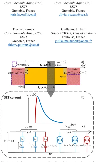
Fig. 1: a) physical system we consider. Note that we virtually extend
Source/Drain junction vertically for modelling purpose as it does not impact the current calculation, as long as we consider vertical incidence only.b) typical shape of the SET current pulse. The red line is the rising part of the pulse while the blue line is the relaxation part.c) simplified equivalent circuit of SET phenomena. Particle impact is modelled as an impulsional voltage at the impact time. RC circuits, describing relaxation modes (blue) or corrective mode (red), are submitted to this voltage and control current generators which
provide SET current pulse at the considered MOSFET electrode. :
conductance of mode (their expression depend on expressions).
P(bulk) , , , , Δ , , 0 Δ 0, , 0 N++(source) N++ (drain) Ion track Virtual S/D a) b) (…) . (…) . . c) SET current
elements number reduction based on physical arguments. Confrontations are made between theoretical and implemented models. Finally, in section III, we show how we can use the SET model to predict some well-known Single Event Effects (SEE) on SRAM cell and shift register.
II. FROM THEORETICAL TO IMPLEMENTED MODEL
reminder of SET theoretical model
The physical system we consider is depicted on Fig.1.a. As it has been explained in [6], the SET current pulse at one of the MOSFET electrode (for example the Drain) can be seen as the superposition of an infinite number of diffusion modes, linked to some time constants . Notice that such a result is valid as long as we consider absorbing boundary conditions at the PN junctions (Source/Bulk and Drain/Bulk). The current density expression at the electrode for a particle striking the device at ( =impact time of the particle) and with the gaussian generation rate described in [6] is then:
. . (1.a) 1 1 0 2 . sin 2 (1.b) . erf . erf (1.c) (1.d)
where is the elementary charge, is the doping density in Source/Drain, . . is the electron mobility in Source/Drain, . is the Linear Energy Transfer, . is the silicon permitivity, is the depth along , / is the reduced splitting width, / is the reduced characteristic length of the gaussian generation, / is the reduced gaussian center location, / is the reduced horizontal position, is the imaginary number, and . is the ambipolar diffusivity. Note that the expression of eq.(1.c) is real because imaginary number cancel out through the difference of imaginary error functions [7]. We can then deduce an equivalent electronical circuit made of an infinite number of RC circuits as explained in [6].
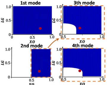
Fig. 2: analytical mapping of the sign of the diffusion modes. In blue color
areas, the mode has positive values while it has negative values in white areas. The red dot represents one given set of values for particle parameters. For this set, we can deduce the first modes which are positive until we reach a negative mode: they are the relaxation modes. In this example, the
first negative mode is the 4th mode so we get 3.
Fig. 3: For different sets of particle parameters values, we compare SET
currents provided by theoretical and implemented model for 0.1μ .
We can see that there is a good matching between the 2 versions of the SET
model, especially for the case → 1. For a particle striking the MOSFET
near the source, the matching is reduced but the temporal behavior is
correctly conserved. Grey areas are out of the restricted range for .
Fig. 4:impact of many identical particles at 2 different times for
0.1μ . We show the drain current provided by the SPICE simulator and the input impulsional voltages describing the particles impacts. We see that the linearity of the equivalent circuit allows us to treat the incidence of many particles without creating a new circuit for each of them: the total SET current is the sum of the SET currents linked to each particles.
0 1 0.00E+00 5.00E-04 1.00E-03 1.50E-03
0.00E+00 2.00E-10 4.00E-10 6.00E-10
Pa rt ic le im pu ls io n( V ) I(A ) t(s) Particle impact
Implemented model
We now have to make the SET model suitable for Verilog-A implementation through reduction of the number of internal nodes. The idea is to keep all diffusion modes dealing with the relaxation part of the SET current pulse (blue line on Fig.1-b) and add a corrective function in order to describe the rising part (red line). This last function is a decreasing exponential with parameters 0, in analogy with diffusion modes parameters , . Notice that this form for the corrective function is an approximation which is still able to catch the behavior of the rising part of the current pulse. It also allows us to recover the RC circuit formalism [6]. We denote for the number of relaxation modes which can be formally defined as the first positive modes, namely verifying, 0 , the
higher positive modes actually adjusting the behavior of the rising part of the pulse in theoretical model. As a result, the SET implemented model is given through:
, (2)
Consequently, we obtain the simplified equivalent electronical circuit illustrated on Fig.1.c, made of RC circuits dealing with current relaxation and one RC circuit which approximates the rising part of the pulse (they respectively correspond to blue and red components on Fig.1.c). We need now to find the 3 unknown parameters , and .
The SET current shape around the impact time and the collected charge (in . are important features for SEE studies. So, we have to guarantee that theses quantities are conserved between theoretical and implemented model. Thus, for determination of , , we first impose implemented (eq. (2)) & theoretical (eq. (1.a-d)) currents at the impact time to be equal. It results in the following equation:
(3) We also impose the implemented & theoretical collected charges to be equal. We obtain another relation:
∑ ∑
(4) If we restrict the range of to ∈ 0.01, 0.91 (which covers most of the cases of particle incidence location in active zone), we guarantee that the series converges with a reasonable number (maximum 100) of iterations. For this range, if 0.3, the series can be predicted to be egal to 0 and otherwise, converges also with a maximum of 100 iterations. Notice that this methodology is valid only for 10 .
The second step is to be able to predict the number of relaxation modes for a particle defined by , , . From eq.(1.a-c), the sign of one mode is determined by the reduced variables and (as sin ⁄ is always positive). 2 Fig.2 shows one example of sign analysis plotting eq.(1-b) in the , plane: we begin with the first mode 1 (which is always the slower relaxation mode), and we then verify the sign of each following modes to deduce the number . In an implementation point of view, we just have to define a “while loop” in the code. This method allows us to adjust the number of internal node related to relaxation according to particle parameters values , without reducing the accuracy of the model in describing this relaxation. We can then inject the value of in eq.(3-4) and the corrective mode is fully determined.
Notice that we have to define a maximal number of internal node dealing with relaxation and we can show that this choice is directly linked to the range of we have chosen for
, determination. If we obtain 0, we reach the limit of the implementation method: in these cases the form of the corrective function is not able to fit with the collected charge
Fig.5: occurrence of SEU in a SRAM cell. a) SRAM schematic with
highlight on struck MOSFET b) observation of the SEU: values of each floating node are switching just after striking of M1. Particle parameters are chosen so that we are at the limit SEU/no SEU. c) layout we consider for the SRAM cell. We map the SEU sensitive areas (blue circles) around the NMOSFET predicted by the proposed model for 2 different LET,
keeping and constant.
no d e v o lt ag e ( V ) Initial state: 1 → 0 Lcell Hcell . . a) b) c)
condition because of the complicated shape of the rising part of the pulse. However, in these specific cases the total current pulse can be approximated by the relaxation modes (so the series term in eq.(2)) without inducing significant errors.
Comparison between theoretical and implemented currents are provided on Fig.3. We notice good matching between the 2 versions of the SET model, especially for the case → 0.91. For a particle striking the MOSFET near the source, the matching is reduced but the temporal behavior is correctly conserved. We also notice better agreement for → 1. One of the main pros of this implemented model is that we can consider the same equivalent circuit for one or several particle impacts thanks to the circuit linearity as evidenced on Fig.4: we just need to define an impulsional voltage pattern (one voltage peak at each impact time) for each kind of particles defined by
, , and the output current will be the sum of each single particle current pulse.
III. PROOF OF CONCEPT ON ELEMENTARY CIRCUITS:
SRAM
The proposed model predicts some well-known SEE at the circuit level. One of them is SEU, which is the bit switch of a SRAM cell following the impact of the particle (Fig.5.a). So, we used the SRAM bit cell and associated MASTAR.VA model cards of BULK MOSFETs (representative of 20nm node 20 proposed in [8]. We initialized the bit state and we analyzed the influence of particle striking during holding on one of the sensitive MOSFETs [1]. Fig.5.b illustrates chronograms of both floating nodes voltages and
during holding time; we clearly see the bit inversion after the particle impact (if we choose proper particle parameters).
It is actually important to study the probability of SEU occurrence, dressing a mapping of sensitive areas of the SRAM in a given radiative environment. To do so, we discretize the SRAM cell surface through elementary surfaces and make particles strike the cell on each ones. We also calculate a shape factor which allows us to adapt the proposed SET model to full 3D gaussian generation. We then check whether or not we get SEU. As explained in Section. I, we need 2 electrodes in order to get the series formalism of eq.(1.a) (so far, we have considered the Source and Drain of the same MOSFET). It is no longer valid if we consider particle incidence outside the channel of SRAM cell MOSFETs. So, we choose the first electrode to be the one where we want to calculate the SET current and the second one is a virtual electrode located far from the particle location so that → 0.91 . In that way, we minimize the effect of this virtual contact while the value of still fit with the range we defined in Section II. On Fig.5.c, we show the resulting sensitive areas mapping for two realistic LET values and considering a basic particle environment (ie: constant , and only vertical incidence on the half of SRAM cell). Notice that the proposed study is illustrative, we have not taken Shallow Trench Insulator (STI) into account as suggested in [3].
Shift register
Another important issue for reliability of ICs are glitches in shift registers, following particle strikes in Flip-Flops [1]. For a shift register (cf Fig.6.a using also MASTAR VA model) working as a delay circuit (series inputs, parallel outputs), the parallel outputs voltages can suffer from an extra shift in time due to particle strike on one of the Flip-Flops. This phenomenon can be predicted by our model as illustrated on chronograms of Fig.6.b & 6.c. Consequently, these proofs of concept show some practical uses of the model but a more complete work including a realistic radiative environment and all possible incidence orientations remain necessary.
IV. CONCLUSION
In this paper, we proposed an implementation method of the SET theoretical model of former work [6]. It resulted in a Verilog-A code which is based on a finite number of RC circuits and which is physical. The input of the model are particles parameters ( , , ), the ambipolar diffusivity , the splitting width and impact times voltage pattern and the output is the SET current. Such a formalism makes the SET model suitable for SPICE simulations and we showed some useful SPICE applications.
ACKNOWLEDGMENT
The author would like to thank STMicroelectronics for use of MATSAR.VA.
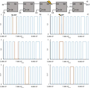
Fig. 6: chronograms of a shift register. a) Schematic and particle impact
location during clock rising. b) observed pattern without SET at 2 successive Flip-Flops and at the output. c) same pattern with SET in Q3: we notice occurrence of a glitch which induces changes in subsequent Flip Flops as it is evidenced by orange lines.
0 1
5.00E-07 7.00E-07 9.00E-07
Q3 t(s) SET a) 0 1
5.00E-07 7.00E-07 9.00E-07
Q3
t(s) No SET
0 1
5.00E-07 7.00E-07 9.00E-07
Q4
t(s)
0 1
5.00E-07 7.00E-07 9.00E-07
Q4
t(s)
0 1
5.00E-07 7.00E-07 9.00E-07
OUT
t(s)
0 1
5.00E-07 7.00E-07 9.00E-07
OU T t(s) CK (…X5) OUT D1 Q1 CK IN D2 Q2 CK CK D3 Q3 CK CK D4 Q4 CK CK D9 Q9 CK CK c) b)
[1] J.L. Autran Soft errors: from particle to circuit. CRC press Taylor & Francis book 2015
[2] D.Munteanu and J.L Autran “Modeling and simulation of Single-Event Effects in Digital Devices and ICs” IEEE Transactions on Nuclear Science, vol. 55, no. 4, pp.1854-1878, Aug. 2008
[3] L.Artola, G.Hubert, K.M. Warren, M.Gaillardin, R.D.Schrimpf, R.A. Reed, R.A. Weller, J.R. Ahlbin, P.Paillet, M.Raine, S.Girard, S.Duzellier, L.W. Massengill, and F.Bezerra “SEU Prediction From SET Modeling Using Multi-Node Collection in Bulk Transistors and SRAMs Down to the 65 nm Technology Node”, IEEE Transactions on Nuclear Science, vol.58, no.3, pp.1338-1346, June. 2011
[4] G.Hubert and L.Artola “Single-Event Transient Modeling in a 65-nm Bulk CMOS Technology Based on Multi-Physical Approach and Electrical Simulations”, IEEE Transactions on Nuclear Science, vol. 60, no. 6, pp. 4421-4429, Dec. 2013
[5] A.Kawakami “A Simplified Model for the Diffusion and Collection of Alpha-Particle-Induced Carriers”, Electronics and Communications in Japan, vol. 69, no. 1, pp.71-78, 1986
[6] N.Rostand, S.Martinie, J.Lacord, O.Rozeau, J.C.Barbé, G.Hubert “Single Event Transient in bulk MOSFETs: original modelling for SPICE application”, SISPAD 2017
[7] R.M.Lahurikar “ Formulae for a complex error function”, bulletin of the Marathwada Mathematical Society, vol. 15, no. 2, pp 42-48, 2014 [8] J.Lacord, G.Ghibaudo, F.Boeuf “MASTAR VA: A predictive and flexible
compact model for digital performances evaluation of CMOS technology with conventional CAD tools”, Solid-State Electronics, vol. 91, pp. 137-146, 2014
[9] G.Hubert, D.Truyen, L.Artola, M.Briet, C. Heng, Y.Lakys, and E.Leduc “SET and SEU Analyses Based on Experiments and Multi-Physics Modeling Applied to the ATMEL CMOS Library in 180 and 90-nm “, IEEE Transaction on Nuclear Science, vol. 61, no. 6,pp 3178-3186, 2014
View publication stats View publication stats