HAL Id: hal-02156759
https://hal.archives-ouvertes.fr/hal-02156759
Submitted on 14 Jun 2019HAL is a multi-disciplinary open access archive for the deposit and dissemination of sci-entific research documents, whether they are pub-lished or not. The documents may come from teaching and research institutions in France or abroad, or from public or private research centers.
L’archive ouverte pluridisciplinaire HAL, est destinée au dépôt et à la diffusion de documents scientifiques de niveau recherche, publiés ou non, émanant des établissements d’enseignement et de recherche français ou étrangers, des laboratoires publics ou privés.
Macroscopic and microscopic determinations of residual
stresses in thin Oxide Dispersion Strengthened steel
tubes
J. L. Bechade, L. Toualbi, Sophie Bosonnet, Olivier Castelnau, Yann de
Carlan
To cite this version:
J. L. Bechade, L. Toualbi, Sophie Bosonnet, Olivier Castelnau, Yann de Carlan. Macroscopic and microscopic determinations of residual stresses in thin Oxide Dispersion Strengthened steel tubes. 9th International Conference on Residual Stresses, ICRS 2012;, Oct 2012, Garmisch-Partenkirchen, Germany. pp.296-303. �hal-02156759�
Macroscopic and microscopic determinations of residual stresses in
thin Oxide Dispersion Strengthened steel tubes
J-L Béchade
1,a,
L. Toualbi
1,b, S. Bosonnet
1,c, O. Castelnau
2,d, Y. De Carlan
1,e 1CEA/DEN/Service de Recherches Métallurgiques Appliquées, 91191 Gif-Sur-Yvette, France
2
PIMM, Arts et Métiers-Paristech, France
a
jean-luc.bechade@cea.fr, b louise.toualbi@onera.fr, c sophie.bosonnet@cea.fr,
d
olivier.castelnau@ensam.eu, e yann.decarlan@cea.fr
Keywords: residual stresses, ODS tubes, X-ray diffraction, elastic theory.
Abstract. To improve the efficiency of components operating at high temperatures, many efforts are deployed to develop new materials. Oxide Dispersion Strengthened (ODS) materials could be used for heat exchangers or cladding tubes for the new GENIV nuclear reactors. This type of materials are composed with a metallic matrix (usually iron base alloy for nuclear applications or nickel base alloy for heat exchangers) reinforced by a distribution of nano-oxides. They are obtained by powder metallurgy and mechanical alloying. The creep resistance of these materials is excellent, and they usually exhibit a high tensile strength at room temperature. Depending on the cold working and/or the heat treatments, several types of microstructure can be obtained: recrystallised, stress relieved…. One of the key challenges is to transform ODS materials into thin tubes (up to 500 microns thick) within a robust fabrication route while keeping the excellent mechanical properties. To prevent cracking during the process or to obtain a final product with low residual stresses, it is important to quantify the effect of the heat treatments on the release of internal stresses.
The aim of this study is to show how residual stresses can be determined on different thin tubes using two complementary approaches: (i) macroscopic stresses determination in the tube using beam theory (small cuts along the longitudinal and circumferential directions and measurements of the deflection), (ii) stress determination from X-ray diffraction analyses (surface analyses, using “sin²Ψ” method with different hypothesis).
Depending on the material and the heat treatment, residual stresses vary dramatically and can reach 800 MPa which is not far from the yield stress; comparisons between both methods are performed and suggestions are given in order to optimize the thermo-mechanical treatment of thin ODS tubes. Introduction
ODS materials, i.e. Oxide-Dispersion Strengthened materials, in ferritic or martensitic structures are developed for cladding purposes in the fourth-generation sodium-cooled fast reactors. Indeed, these high performance materials present many advantages since they combine remarkable mechanical strength at high temperature and outstanding irradiation resistance. ODS materials afford not only negligible swelling under irradiation, but equally excellent creep properties, thanks to the nano reinforcements present in the matrix [1-3].
Elaboration of ODS materials presents a specific step known as mechanical alloying (Fig. 1), which is needed to obtain nano strengthened oxides in the ferritic matrix. It is now generally admitted that the mechanisms involved in the formation of nano phases in ODS alloys include the dissolution of yttrium oxides during grinding and a precipitation of nano phases (Y, Ti, O) during hot consolidation. The nano precipitates giving their high strength to the ODS materials are present just after hot extrusion and before cold manufacturing [4]. This specific fabrication sequence implies specific mechanical behavior of ODS mother tube, i.e. low ductility and high hardness at room temperature, which complicates the cold manufacturing of ODS cladding tubes and requires the introduction of intermediate heat treatments between the cold rolling passes in order to soften the material and avoid any damage during the fabrication route [5-7].
A good understanding of the microstructural evolutions but also mechanical state in the course of manufacturing represents a crucial point for the global optimization of the ODS fabrication route. This paper is focused on Fe-9Cr-1W ODS material, elaborated at CEA, during the last step of the fabrication route (last cold rolling pass and final heat treatment) and concerns the residual stresses evolution.
Fig. 1: ODS cladding tubes fabrication steps [8]. Studied material
Metallic powders atomized by Aubert & Duval and yttria powder were mechanically alloyed under hydrogen by Plansee. They were consolidated by hot extrusion to obtain raw tubes, and then manufactured into thin cladding tubes using cold rolling passes punctuated by intermediate heat treatments for stress relief purposes. The obtained ODS (so-called “martensitic”) grade has a nominal composition of Fe-9Cr-1W-0.2Ti-0.3Y2O3. It presents a large austenitic domain at high
temperature which allows complete phase transformation from ferrite to austenite. Characteristic temperatures and critical cooling rates are determined thanks to the Continuous Cooling Transformation (CCT) diagram [8].
During the last step of the fabrication process, i.e. manufacturing into thin cladding tube (500µm thick) by mean of pilger cold rolling process, it is very important to control the hardening of the material, in order to prevent any damage. The low cold workability of ODS raw tubes complicates the manufacturing and implies intermediate softening heat treatments punctuating the cold working passes. In order to guaranty a safe forming, microstructure evolutions during the manufacturing are followed by mean of hardness measurements all along the fabrication route [9] (Fig. 1).
Mother tube heat treatment consists in a homogenization at 1050°C for 1h followed by a slow cooling, leading a softened ferritic structure (hardness value around 300HV1). Six cold rolling
passes are conducted with a cross-section reduction ratio of about 25% for each pass. Intermediate softening heat treatments are performed every two passes [10]. After about 40% cold working, hardness increases up to 400HV1. This value can be considered as a critical level above which cold
rolling become unsafe [7]. The intermediate heat treatment is performed in the austenitic domain, i.e. at 1050°C during 1h, and followed by a slow cooling (0.03°C/s). It leads to a significant decrease of the hardness until its initial value of 300HV1. The softened raw tube can be further
cold-worked without any risk of damage. These operations, i.e. cold rolling passes and intermediate annealing in the austenitic domain, are repeated until reaching the final cladding tube geometry: 10.73mm external diameter and 500µm thickness. A last annealing is performed in order to ensure good mechanical properties to the final cladding tube. A homogenization at 1050°C for 30 minutes
is carried out and followed by a fast cooling (around 1°C/s), which corresponds to the critical cooling rate leading to the formation of a martensitic structure. The final cladding tube is then tempered at 750°C for 1h.
Fig. 2: Hardness evolution during the manufacturing process [10].
In this paper, Fe-9Cr-1W ODS tube is studied at two steps of the fabrication route: after the last cold working pass, i.e. after about 40% of cumulated cold work (sample named J95-M1 or CR in Fig. 2) and after the final heat treatment of 1050°C / 30min + fast cooling + 750°C/1h (sample named J95-M3 or FHT in Fig. 2).
Microstructures are drastically different between the two samples: J95-M1 sample shows fine grains elongated is the rolling direction (a few µm thick and around 10 µm long) while J95-M3 sample presents an equiaxed microstructure similar to the mother tube one. The complete phase transformation from ferrite to austenite allows eliminating the anisotropic microstructure induced by cold rolling [10].
As already explained, residual stresses have to be minimized to avoid any damage of the tube at every step of the fabrication process. To follow the evolution of internal stresses for these two ODS tubes, two complementary approaches have been followed: (i) determination of the macroscopic stress by means of small cuts along the longitudinal and circumferential directions, measurements of the tab deflection, and interpretation in terms of stress using the elastic beam theory, (ii) localized stress determination from X-ray diffraction analyses using the standard “sin²Ψ” method.
Residual stresses determination
Average macroscopic determination. Longitudinal cuts along the tube are performed on the two samples in order to obtain two symmetrical tabs. The cladding tube of Fig. 3a corresponds to the J95-M1 sample taken just after cold working. The considerable internal stresses due to the rolling process induce a macroscopic displacement of the tabs. On the contrary, the second cladding tube, which is softened by a heat treatment performed in the austenitic domain (J95-M3 sample), shows no displacement after cutting (Fig. 3b).
a) b)
Fig. 3: 9Cr-ODS cladding tube a) after 40% cold working (J95-M1) and b) after final heat treatment 1050°C/30min + fast cooling + 750°C/1h (J95-M3).
200 300 400 500 H a rd n e ss HV 1 Mother Tube HT CR FHT HT CR CR Fabrication route CR : Cold Rolling ~40%
HT : Intermidiate Heat Treatment 1050°C/1h, slow cooling rate FHT : Final Heat Treatment 1050°C/30min, fast cooling rate, Tempering 750°C/1h
Here, thanks to the large aspect ratios of the tabs, the elastic beam theory can be applied to interpret the measured displacements. It has to be noted that the cutting of these fine tabs relaxes only part of the internal stresses; the final internal stress in the tab does not necessarily vanish. Equilibrium ensures that the bending moment in the tabs vanishes, but through-thickness gradients of residual stresses can still persist. The measured tab deflection corresponds to the stress increment between the initial tube and the cut tab, and is associated with the bending moment originally present in the tubes. Assuming that the tab deflection is purely elastic, i.e. does not generate any plastic strain, the increment of through-thickness stress distribution between the initial and final (i.e. cut) configurations is linear (Fig. 4), and the maximal value of the residual stresses increment along the longitudinal axis z of the tube reads
with E the Young modulus, L the tab length, h its thickness, and u(L) the maximum displacement along the radial direction x. The quantity ∆σzz corresponds to the stress on the outer tube surface
that is released during the cutting.
Fig. 4: Stress distribution on the tab along the longitudinal axis of the tube.
Similar measurements (in both cases, displacements were measured carefully using laser shadowscopy: accuracy of few µm) were performed for ring specimen in order to estimate the maximum residual stress increment along the circumferential direction (Fig. 5): when longitudinal cuts are performed, the diameter is increasing depending on the macroscopic residual stress level. The maximal value of the residual stress increment along the circumferential direction of the tube (θ) reads
with R0 and R the ring radius before and after cutting, respectively.
a) b)
Fig. 5: 9Cr-ODS cladding ring a) after 40% cold working (J95-M1) and b) after final heat treatment 1050°C/30min + fast cooling + 750°C/1h (J95-M3).
Average microscopic determination. These stresses, named type-I, σI, vary within the body of the component over a range much larger than the grain size. Then, X-Ray Diffraction (XRD) has been used to determine residual stresses values using the standard “sin²Ψ method”. It is based on interplanar spacing used as strain gauge, considering that macroscopic residual stresses in the material cause changing of interplanar distance d. XRD data were obtained using a
Bruker-D8-Δσzzmax =u L .EL2 h (1)
Discover device with Cu-Kα radiation, Polycap focusing optic and 1 mm collimator to reduce beam size, ¼ circle Eulerian cradle and a scintillator as point detector. Note that with such a setup, since the XR beam penetration is small (few microns only), the measured stress corresponds to the outer surface of the tube. XRD enables interplanar spacing calculation from measuring Bragg’s angle and using Bragg’s equation (Eq. 3). Differentiating Eq. 3 provides the elastic strain ε from Bragg’s angle shift ∆θ (Eq. 4).
where d, θ, λ, ε, and ∆θ are the interplanar distance, the diffraction Bragg’s angle, the radiation wavelength, the elastic strain, and the Bragg’s angle shift, respectively. A diffraction peak at quite high angle has been chosen to obtain a good accuracy in residual stresses determination and at the same time peak intensity high enough: all things considered (310) planes at 2θ=115° have been selected. The standard “sin²Ψ method” has been used to interpret XRD data; it relies on several assumptions, i.e. homogeneous and isotropic material, linear elastic behavior, biaxial stress state for which only σxx, σxy, and σyy, are non-vanishing, and vanishing residual stresses at the grain scale
(so-called second order stresses). This leads to the expression [13, 14]:
with E and ν respectively the Young modulus and Poisson ratio regarding the radiocrystallographic elastic constant, and σφ = σxx for φ=0, σφ = σyy for φ = π/2. Strain values are recorded for different
sample tilt angle (ψ) at constant azimuth angle φ. Strain vs. sin²Ψ is plotted to estimate the stress values. Two angles φ have been used in order to determine the axial stress (along the longitudinal direction of the tube) and the hoop stress (along the circumferential direction). 20 negative and positive tilt angles ψ have been used for sin² ψ values ranging from 0 to 0.5. A stress free sample of the same material has been prepared and measured in order to provide an estimation of d0. The
experimental procedure, i.e. device and sample positioning, was validated thanks to an unstressed Si powder sprayed at the surface of a ring showing similar dimensions as the specimens, and also thanks to a reference sample with a well-known stress level (shot peened austenitic stainless steel). The obtained strain vs. sin²Ψ plots are given in figure 6.
2 d sinθ = nλ (3) ε = ∆dd = −cotθ ∆θ (4) ε = ∆dd = d−d0 d0 = 1+ν E sin2Ψ− ν E σφ (5)
Fig. 6: Strain vs. sin²Ψ for cold worked (J95-M1) and final heat treated (J95-M3) rings along axial (σzz) and circumferential (σθθ) directions.
Results
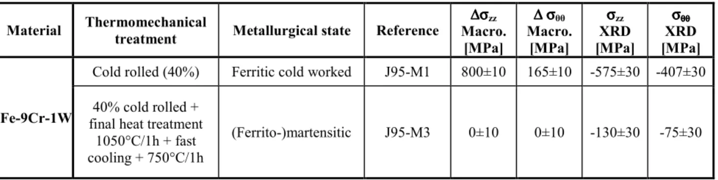
Results with both approaches are given Table 1. The maximal value of the stress increment for the cold-worked cladding tube is obtained through the macroscopic calculation and is about 800 MPa, along the axial direction. Along the same direction, the heat treated cladding tube exhibits negligible internal stresses. Similar results are obtained for circumferential direction with a lower residual stress level: 165 MPa for cold rolled tube compared to ~0 after the final heat treatment.
This macroscopic demonstration prove the preponderant effect of the α / γ phase transformation to release the internal stresses induced by the cold rolling process. This very important result has been also confirmed by microstructural analyses using TEM but also mechanical testing (hardness especially) [10].
Table 1: Residuals stresses along axial and circumferential directions from macroscopic measurements and XRD analyses.
It is also very interesting to make relationships between these results and Vanegas’s PhD work [12] concerning numerical approaches of the pilgering process used during the ODS tube fabrication at CEA. Finite elements calculations of the process taking into account cyclic elastic– plastic constitutive model [11] identified from fatigue tests show similar results with a better description of the mechanical local state for a specific section of the tube at different depth in the
Material Thermomechanical
treatment Metallurgical state Reference
∆ ∆ ∆ ∆σσσσzz Macro. [MPa] ∆ ∆ ∆ ∆ σσσσθθ Macro. [MPa] σ σ σ σzz XRD [MPa] σ σ σ σθθθθθθθθ XRD [MPa] Fe-9Cr-1W
Cold rolled (40%) Ferritic cold worked J95-M1 800±10 165±10 -575±30 -407±30
40% cold rolled + final heat treatment
1050°C/1h + fast cooling + 750°C/1h
thickness of the tube and for different generatrices (Fig. 7). In fact a real comparison with this numerical approach is not possible with the macroscopic approach using cutting. Integrations of the mechanical state along the length of the tab or the ring have to be done for valid comparisons. For example, longitudinal cuts performed along 12 generatrices show that in any case the stress state from average macroscopic determination is in tension (the macroscopic displacement of the tab is always in the same direction and range, as observed Fig. 3a).
Fig. 7: Residual stresses computed by numerical approaches along axial (σzz) and circumferential
(σθθ) directions [12].
Now, looking at XRD results noticeable differences with macroscopic calculations are obtained. But one has to keep in mind that residual stresses determine by XRD techniques are more local than what is obtained from cutting of specimen machined from tubes, and that XRD measures the actual stress level while the cutting only the stress release between two configurations. One interesting point is that residual stresses obtained from XRD measurements are significantly reduced after final heat treatment and, as for macroscopic calculation, the highest value is obtained along the axial direction of the tube.
Nevertheless, according to the assumption proposed to evaluate the stress distribution on the tab along the longitudinal axis, the external layer has to be in tension while according to XRD measurements it is in compression. This major difference could be attributed to the fact that XRD analysis is performed at few microns depth (in our case, estimation of the diffracting volume is around 1.5x1x0.004 mm3) and strongly depends on the local hardening due to the process. This point has to be addressed in future experiments by measuring the local stresses at different depths. Looking at Vanegas results, one can see that for specific generatrices, compressive stresses can be obtained whereas for others tensile stresses are found. Accurate analyses with XRD are under progress in order to make direct comparisons with Vanegas’s numerical modeling at different depths and along different generatrices.
Conclusion
Fabrication process of ODS thin tubes, especially during the cold pilgering step, induces high residual stresses damaging the material during the fabrication. Residual stresses have been determined on two thin tubes, before and after heat treatment, using two complementary
approaches: (i) determination of macroscopic stresses released in the tube using small cuts along the longitudinal and circumferential directions and measurements of the bending, (ii) localized stress determination from X-ray diffraction analyses (using “sin²Ψ” method).
Macroscopic and XRD determinations show the strong effect of the heat treatment (reduction of stress along axial and circumferential direction) but stresses levels are significantly different between the two techniques: this can be understood taking into account the fact that XRD brings more local residual stresses analysis. Tab deflection provides information relative to the bending moment originally present in the tube, while XRD is a measurement of the stress in the outer tube surface.
Acknowledgements
We want to thank Pierre-Edouard Fosse for his help concerning this study during his internship at CEA Saclay, EdF and AREVA for their financial support.
References
[1] P. Yvon, F. Carré, J. Nucl. Mater. 385 (2009) 217-222.
[2] R. Lindau, A. Möslang, M. Rieth, M. Klimiankou, E. Materna-Morris, A. Alamo, A.-A.F. Tavassoli, C. Cayron, A.-M. Lancha, P. Fernandez, N. Baluc, R. Schäublin, E. Diegele, G. Filacchioni, J.W. Rensmanh, B.v.d. Schaaf, E. Lucon, W. Dietz, Fusion Eng. Des. 75-79 (2005) 989-996.
[3] Y. de Carlan, J.-L. Béchade, P. Dubuisson, J.-L. Seran, P. Billot, A. Bougault, T. Cozzika, S. Doriot, D. Hamon, J. Henry, M. Ratti, N. Lochet, D. Nunes, P. Olier, T. Leblond, M.-H. Mathon, J. Nucl. Mater. 386-388 (2009) 430-432.
[4] J. Alinger, G.R. Odette, D.T. Hoelzer, J. Nucl. Mater. 329-333 (2004) 382-386.
[5] P. Dubuisson, Y. de Carlan, V. Garat, M. Blat, J. Nucl. Mater. V428(1-3) (2012) 6-12. [6] S. Ukai, M. Fujiwara, J. Nucl. Mater. 307-311 (2002) 749-757.
[7] M. Inoue, T. Kaito, S. Ohtsuka, Materials for Generation IV Nuclear Reactors, Cargese, Corsica, 2007.
[8] P. Olier, J. Malaplate, M.H. Mathon, D. Nunes, D. Hamon, L. Toualbi, Y. de Carlan, L. Chaffron, J. Nucl. Mater. V428 (1-3) (2012) 40-46.
[9] L. Toualbi, C. Cayron, P. Olier, J. Malaplate, M. Praud, M.-H. Mathon, D. Bossu, E. Rouesne, A. Montani, R. Logé, Y. de Carlan, J. Nucl. Mater. V428 (1-3) (2012) 47-53.
[10] L. Toualbi, C. Cayron, P. Olier, P.-E. Fosse, R. Logé, Y. de Carlan, Relationships between mechanical behavior and microstructural evolutions in Fe 9Cr-ODS during the fabrication route of SFR cladding tubes, submitted to J. Nucl. Mater. (2012).
[11] Y. de Carlan, E Vanegas, L. Toualbi, K. Mocelin, R. Logé, Optimisation of the fabrication route of ferritic/martensitic ODS cladding tubes: Metallurgical approach and pilgering numerical modeling, submitted to Fast Reactors, Paris 4-7 march 2013.
[12] E. Vanegas-Marquez, Numerical modeling of ODS steel tubes pilgering, PhD, ENSMP-ParisTech., December 2011.
[13] I.C. Noyan, J.B. Cohen,Residual Stress Measurement by Diffraction and Interpretation,
Materials Research Engineering, Springer-Verlag, 1987.
[14] T. Bretheau, O. Castelnau, Les contraintes résiduelles : d'où viennent-elles ? Comment les caractériser ?, Rayons X et Matière (RX2006), Chap. 5 (p. 123-154), Ed. R. Guinebretière, P. Goudeau, Hermès, 2006.
![Fig. 1: ODS cladding tubes fabrication steps [8].](https://thumb-eu.123doks.com/thumbv2/123doknet/12950383.375846/3.892.186.718.236.550/fig-ods-cladding-tubes-fabrication-steps.webp)
![Fig. 2: Hardness evolution during the manufacturing process [10].](https://thumb-eu.123doks.com/thumbv2/123doknet/12950383.375846/4.892.291.607.187.404/fig-hardness-evolution-manufacturing-process.webp)

![Fig. 7: Residual stresses computed by numerical approaches along axial (σ zz ) and circumferential (σ θθ ) directions [12]](https://thumb-eu.123doks.com/thumbv2/123doknet/12950383.375846/8.892.196.730.240.659/residual-stresses-computed-numerical-approaches-axial-circumferential-directions.webp)
