HAL Id: in2p3-00996457
http://hal.in2p3.fr/in2p3-00996457
Submitted on 6 Apr 2020
HAL is a multi-disciplinary open access
archive for the deposit and dissemination of
sci-entific research documents, whether they are
pub-lished or not. The documents may come from
teaching and research institutions in France or
abroad, or from public or private research centers.
L’archive ouverte pluridisciplinaire HAL, est
destinée au dépôt et à la diffusion de documents
scientifiques de niveau recherche, publiés ou non,
émanant des établissements d’enseignement et de
recherche français ou étrangers, des laboratoires
publics ou privés.
GANIL axial injection design with an ECR ion source
M.P. Bourgarel, E. Plawski, L. Bex, P. Di Bernardo
To cite this version:
M.P. Bourgarel, E. Plawski, L. Bex, P. Di Bernardo. GANIL axial injection design with an ECR ion
source. Tenth International Conference on Cyclotrons and their Applications, Apr 1984, East Lansing,
United States. pp.161-164. �in2p3-00996457�
J < —
r«,?^o?>s i
GANIL AXIAL INJECTION DESIGN
WITH AN ECR ION SOURCE
M.P. BOURGAREL, E. PLASWKI,
XL. BEX, P. DI BERNARDO
x xGRAND ACCELERATEUR NATIONAL D'IONS LOURDS
BP 5027 14021 CAEN CEDEX (FRANCE).
x
INSTITUT PROBLEMOW JADROWYCH, SWIERK, POLAND.
X X
FACULTA DI FISICA. CORSO ITALIA 53-95100 CATANIA
I
GANIL AXIAL INJECTION DESIGN WITH AN ECR ION SOURCE
M.P. BOURGAREL, E. PLAWSKI*, L. BEX, P. DI BERNARDO**
GRAND ACCELERATEUR NATIONAL D'IONS LOURDS BP 5027 14021 CAEN CEDEX (France)
SUMMARY. The main featurei of the adaptation of an hyperboloid inflector to the central region of the injector cyclotron and the bean transmission are presented.
INTRODUCTION
The maximum energy of GANIL depends on the initial charge Zl. Actually, GANIL is in operation with the first injector cyclotron '>2 and an internal PIG ion
source.
A 2nd injector, identical to the first one, has been planned in view of giving more flexibility to the machine operation. It is being assembled and is planned 'to be tested in October 84.
In order to increase the energies, mostly on the 80-to-170 mass range where the users1 demand is strong,
and also in order to get a mora continuous working time than with the internal source, in addition to this one, an ECR 3 source will be incorporated to the 2nd injector.
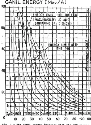
Fig. t shows the energies that can be obtained from an initial charge Zl. Limits are due to the maximum magnetic field and stripping efficiency. As seen from these curves, an ECR source is especially convenient to produce these charges (Aro+, Kr'0+, Xe'3+
...) and to reach 90, 65 and 45 MeV/A respectively.
The construction of the ECR source (MINIMAFIOS) -identical to the SARA and KVI onea - has been under taken in 1983 by R. Geller and his group at CEN-G. They have tested it successfully for N2 + (320 euA) and
A r " (40 euA) ; Kr and Xe will be measured soon. Emittances, expected to be < 150 u mn-mrad at 20 KV, were in fact recently measured to be 150 tm-mrsd. The assembling on GANIL is planned for September and first tests in December.
A compact injection system has been designed last year to transport the ECR beam to the 2nd injector, over a distance about 6 m and it is partly under construction. The axial injection operation is expected in June 1985.
This paper presents the main features of the resulting design :
a) the system will be operating with an external source as well as with an internal source. Thus, the requirement is to conserve the central region that has been designed for the internal source to meet injector specifications (phase width and emittance), except for the puller which is removable.
b) the large turn separation (the radius of the first orbit is Ro - 6.8 cm) allows to choose a hyper boloid type inflector * for its exceptional optical properties, although it needs an off-axis injection.
c) the ion source can be located in the injector hall which is radiation-free : thus the beam handling system is short and it has been designed without too much sophistication : a to ally achromatic version *eems to be unjustified £c the ECR beam characterized by a very small energy disi rsion (30 ev/per charge). Therefore a version has beei calculated, which is dispersive in the horizontal plane, and achromatic in the vertical plana to allow an RF buncher.
d) users' experience she od the disadvantage of analyzing just after the pulUr, due to the ECR fringing field effects on the analyzing magnet. So we have choosen to refocus the beam with a solenoid.
GANIL ENERGY CMev/A)
0
10 20 30 40 50 60 70 80 90 10C
Fig. I - The GANIL energy increase with the ECR source.
t Instytut Problemow Jadrowych, Swierk, Poland. ** Facolta di Fisica. Corso Italia 53-95100 Catania
Beam matchinR in the central region
I. EnerRy adaptation
The actual central region has been designed for an internal ion source, operation on the 4th har monie and accurate values of energy and phase at the puller entrance, to obtain a well centered bean. (Position Fo on the Fig.2).
Calculations show that this energy after the first gap - 97Z of the maximum energy ZV - will be conserved with the axially injected bean if this gap width is matched to the injection energy. Central pha se has also to be adjusted to another value, so that the puller position Po has to be shifted.
Fig2. shows the reference particle trajectory and the geometry of the central region with the new puller entrance PA which natches the beam leaving the inflector to tho fixed orbit pattern of the cyclotron : Che injection energy it 0,217 x maximum energy ZV, the accelerating gap width P3P4 is 3.1 cm, the central pha se is -76' at P3 and 71* at P4 ; the starting phase width can be 30* at P3 with a small phase compression effect giving 17* at P4 and with an energy dispersion
of It.
' The injection energy determines the hyperbolic inflector parameters given in Table I and on Fig3. The choice of the magnetic radius Rmat - 3.2S cm is a compromise between a voltage range of 8 - 20 KV on the ECR source and the inflector height compatible with the magnet gap. The inflector position (entrance PI and exit P2) is also the result of a compromise bet ween RF voltage holding conditions and an off-axis li mited to 4 cm.
3* Beam matching conditions
2 General orbit code calculations have been made with the internal ion source and have allowed to define the injector acceptance (Fig4).
In the (r, r, v) space, the critérium to get the mat ching area is to select the particles which fill the specifications on ejected beam qualities given in ta ble I and needed for the injection in the SSCI. In the (z, z, •) space, in addition Co these conditions the beam height is limited to 30mm.
As seen from the curves of Fig4. the ECR source emittances, expected to be < ISO w mra-mrad, will be completely included into the acceptance areas.
So phase space areas are fixed at the exit of the inflector.
\ \
is* 0.-10* rfcrti a.*" - 2 5 — m -525» TOTALtr rOl.lOOO— mttt V»'M
\
IZ.2,t)-W0«w»-4Figfr. The horizontal et vertical injector acceptances at P3 (in j. energyH° meet beam specifications. The central phase +o is -76* and the starting pha se width is 30*.
Fig2-. Central region on the 4th harmonic with the re ference trajectory starting from the hyperboloid inflector.
•Fig3. The hyperboloid inflector parameters and electri cal considerations.
Table I
Fixed cyclotron parameters for the Axial injection
R.F frequency range (MHz) Harmonic mode
Magnetic range (T) Max. Dee Voltage V (kV) Max. Ratio Z/A First orbit radius (cm) Free gap (cm)
Inflector parameters Max. ECR source voltage (kV) Magnetic radius RMAG (cm) Injection energy / ZV ratio Radius Ro (cm) Radius Rs (cm) Height (cm) Distance PI P2 (cm) Distance PIC (cm) Rin radius (cm) Rout radius (cm)
Distance between electrodes (cm) Max. Voltage on electrodes (kV)
Specifications on ejected beam qualities Phase width (degrees)
Total energy dispersion Emittance (n x mm x mrad) 6.5 - 14 4 0.8 - ! .7 90 0,136 6.8 18. 20 •3.25 0.2177 15.92 19.5 7.96 7.14 5.65 4. 6.25 +2 . i 5 < 15* < IZ < 45
Beam transmission through the cyclotron magnet
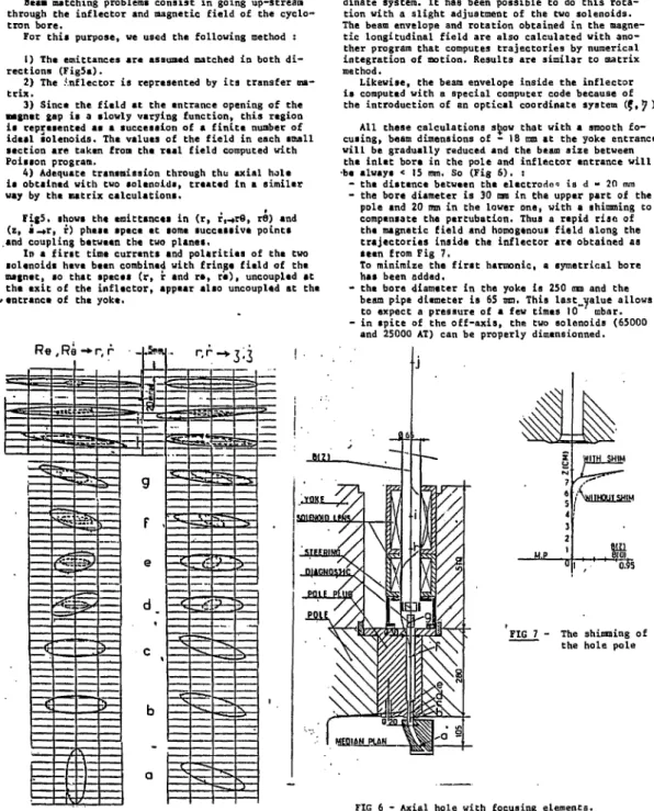
Beast matching problems consist in going up-stream through the inflectar and magnetic field of the cyclo-tron bore.
For this purpose, we used the following method :
1) The emittances are assumed matched in both di-rections (Fig5a).
2) The .\nflector is represented by its transfer ma-trix.
3) Since the field at the entrance opening of the magnet gap is a slowly varying function, this region is represented as a succession of a finite number of ideal solenoids. The values of the field in each small section are taken from the real field computed with Poisson program.
4) Adequate transmission through the axial hole ia obtained with two solenoids, treated in a similar way by the matrix calculations.
Fig5. shows the emittancta in (r, r,-tr9, r9) and (i, i-»r, r) phase apace at some successive points and coupling between the two planes,
In a first time currents and polarities of the two solenoids have been combined with fringe field of the magnet, so that spaces (r, r and re, re), uncoupled at Che exit of the inflector, appear also uncoupled at the /entrance of the yoke.
R « , Rè -* r, r
Then design considerations led us to adopt a beam line injection, rotated by 15* with the inflector coor-dinate system. It has been possible to do this rota-tion with a slight adjustment of the two solenoids. The beam envelope and rotation obtained in the magne-tic longitudinal field are also calculated with ano-ther program that computes trajectories by numerical integration of motion. Results are similar to matrix method.
Likewise, the beam envelope inside the inflector is computed with a special computer code because of the introduction of an optical coordinate system (f,^ )
All these calculations sh^ow that with a smooth fo-cusing, beam dimenaions of - 18 mm at the yoke entrance will be gradually reduced and the beam aiz& between
the inlet bora in the pole and inflector entrance will •be always < IS mm. So (Fig 6 ) . :
- the diatance between the electrodes is d - 20 mm - the bore diameter is 30 am in the upper part of the
pole and 20 mm in the lower one, with a shimming to compensate the pertubation. Thus a rapid rise of the magnetic field and homogenous field along the trajectories inside the inflector are obtained as seen from Fig 7.
To minimize the first harmonic, a symatrical bore has been added.
- the bore diameter in Che yoke is 250 mm and Che beam pipe diameter is 65 mm. This last_yalue allows to expect a pressure of a few times 10 mbar. - in spite of the off-axis, the two solenoids (65000
and 25000 AT) can be properly dimensionned.
FIG 7 The shimming of the hole pole
FIG_5 - phase space ellipses along the axial trajectory
FIG 6 - Axial hole with focusing elements The axial field Bz is plotted.
External beam transport system
Calculations were made using the program TRANSPORT. The adopted version (Fig S) is dispersive in the hori zontal plane and achromatic in the vertical plane. It consists of two principal sections :
The first one incorporates :
!) a solenoid to refocus the beaa of the ECR source 2) a momentum analyzing magnet (102°) with a separa ting power of i.5 cm/35 dp/p with the objecc slit width of S ma.
3) Four magnetic quadrupoles to match the transverse spaca-phaae to the yoke acceptance.
4) a RF buncher, not yet defined. Since the drift length in the cyclotron yoke is small (80 cm) it is . necessary to place the bunchar in the horizontal
section. From this point on, the second section has to be achromatic.
The second section eonaiati of a 90* vertical BROWN type achromatic band.
Fig 9. ghovs the envelope calculated for a 150 * tnm-mrad Ar beam, matched to the entrance of the yoke. Four beam profile monitors located before and after the two bends, measure the beam center shift and dimensions, that will allow to compute the experimental emittance and to adjust the adaptation.
Besides the ECR source, the possibility of using the same beam transport line to inject beams delivered by a PIG source, has been investigated. A second entrance into the analyzing magnet has been provided with a 69*5 bend and 56 cm radius, which will not be described here.
References
1, H. P. Bourgarel and AL. - The GANIL injector desi gn - 8th Int. Cycl. Conf. - 1978 p 1941
2, M, P. Bourgarel and AL. - Progress report and first operation of the GANIl. injector - 9th Int. Cycl. Conf. 1981 - p 121
3. R. Geller and B. Jacquot - Nucl. Inst, and methods 184 (1981) p 293
4. R. W. Huiler - Novel inflectors for cyclic accule-ratora duel. Inst, and Meth. 54 (1967) 29 - 41
Momnmrat stcnoN
_aai___2i!5S fflSL a»^ MMS n.u
nmm JKTIOH
Beam line proposal. The first section is horizontal above the cyclotron ! analyse and focusing ; mat ching to the injec tor acceptance. The second section is vertical and achro matic.
FIG 9 Envelope calculated for a 150 II mm-orad Ar6t baam ; BR-0.04927 T.mj
ECR voltage - 17,7 kV. Beam is matched to the entrance of the yoke.