HAL Id: hal-01499500
https://hal.archives-ouvertes.fr/hal-01499500
Submitted on 31 Mar 2017
HAL is a multi-disciplinary open access archive for the deposit and dissemination of sci-entific research documents, whether they are pub-lished or not. The documents may come from teaching and research institutions in France or abroad, or from public or private research centers.
L’archive ouverte pluridisciplinaire HAL, est destinée au dépôt et à la diffusion de documents scientifiques de niveau recherche, publiés ou non, émanant des établissements d’enseignement et de recherche français ou étrangers, des laboratoires publics ou privés.
Design and dynamic behaviour of a cold storage system
combined with a solar powered thermoacoustic
refrigerator
Maxime Perier-Muzet, Jean-Pierre Bedecarrats, P Stouffs, Jean
Castaing-Lasvignottes
To cite this version:
Maxime Perier-Muzet, Jean-Pierre Bedecarrats, P Stouffs, Jean Castaing-Lasvignottes. De-sign and dynamic behaviour of a cold storage system combined with a solar powered ther-moacoustic refrigerator. Applied Thermal Engineering, Elsevier, 2014, 68 (1-2), pp.115-124. �10.1016/j.applthermaleng.2014.03.065�. �hal-01499500�
1
Design and dynamic behavior of a cold storage system combined with a
solar powered thermoacoustic refrigerator.
Maxime Perier-Muzeta, Jean-Pierre Bedecarratsa*, Pascal Stouffsa, Jean Castaing-Lasvignottesb
a Univ. Pau & Pays Adour, LaTEP, EA 1932, Laboratoire de Thermique, Energétique et Procédés, ENSGTI, Rue Jules Ferry,
BP 7511, F-64075, France
b
Université de La Réunion, Laboratoire de Physique et Ingénierie Mathématique pour l’Energie et l’environnemeNT (PIMENT), ESIROI, 117, rue du Général Ailleret, 97430 Le Tampon, Ile de la Réunion, France
*Corresponding author. Tel.: +33(0)559407717; fax: +33(0)559407740.
E-mail address: jean-pierre.bedecarrats@univ-pau.fr (J-P. Bédécarrats).
Abstract:
A heat powered thermoacoustic refrigerator consists in a thermoacoustic engine that produces acoustic work utilizing heat, coupled to a thermoacoustic cooler that converts this acoustic energy into cooling effect. These machines have already proved their capability in laboratory or in space refrigeration. Previous studies have also demonstrated the possibility of using concentrated solar energy as thermal energy sources for low power heat driven thermoacoustic refrigerators. As other solar refrigeration systems, even if the cooling demand generally increases with the intensity of the solar radiation, one of the major difficulties is to insure a frigorific power supply when there is no, or low, solar radiation. The aim of this work is to study a kWscale solar thermoacoustic refrigerator capable to reach temperatures of the industrial refrigeration domain. This refrigerator is combined with a latent cold storage in order to guarantee a sufficient cooling capacity to face to refrigeration loads in spite of the production fluctuations. A description of the studied prototype is done and the model developed to describe the transient behaviour of the main components of this machine is introduced. The results obtained with a simulation of one week with real solar radiations are presented and the behaviour and the energetic performances of the entire system are analysed. Finally the impact of the sizing of the cold storage system is discussed. With the best storage design, the system is capable to supply a cooling power of 400 W at a temperature equal or lower than - 20 °C with an average Coefficient Of Performance of the solar thermoacoustic refrigerator equal to 21%.
Keywords:
Solar energy; solar refrigeration; thermoacoustic refrigerator; cold latent thermal storage; Phase Change Material (PCM).
1. Introduction
Energy use for refrigeration has risen sharply in recent years. Nowadays, the major part of this production is provided by electrically driven vapour compression machines. Globally, the refrigeration devices consume roughly 15 % of the world electricity production. The forecasts for the refrigeration indicate an increase in the number of units in operation in the coming years. While responding to environmental challenges (greenhouse gases emissions reduction), the future cooling machines should not be primary energy intensive and should use environmentally friendly fluids [1, 2] to ensure the refrigerating production in the years to come.
Thanks to numerous possible combinations between solar thermal collectors and heat driven cooling machines, solar cooling equipment seems to be an interesting alternative [3]. Among these possibilities, the coupling of a solar concentrator with a heat driven thermoacoustic refrigerator is a promising technology. Compared to the other
refrigeration technologies, heat driven
thermoacoustic machines have several advantages with no moving part and natural working fluid such as helium, argon or air [4]. Over the last decades, experimental investigations have been carried out on these machines. They have proven their ability to reach very low temperatures, compatible with the liquefaction of gases such as natural gas [5], nitrogen [6] or hydrogen [7]. Other
2 studies have demonstrated the possibility to use
thermoacoustic refrigeration for higher temperature applications like food refrigeration
[8]. The couplings of thermodriven
thermoacoustic refrigerators and solar concentrators have also already been experimentally studied, particularly in the case of low power prototypes [9, 10]. Other investigations have been carried out on the coupling of a solar concentrator and a thermoacoustic machine to convert solar energy into electricity [11]. The impact of the variation of the tilted angles on the performances of a thermoacoustic engine driven by two-axis solar collector which follows the solar position has been studied [12].
Although the cooling demand is generally higher when the sun is shining, the intermittent nature of solar energy is one of the major constraints for using solar cooling systems. To meet the time-dependency of the primary energy supply and end-use requirement, a thermal energy storage is generally used [13]. Various configurations of this element can be achieved; accumulating the hot
energy for continuously supplying the
refrigeration system or storing the energy produced by the refrigerator. The latter can be stored in the form of sensible heat (in liquid or in solid), latent heat of a Phase Change Material (PCM), or by chemical reaction. The choice of the system depends on various criteria such as the amount of energy that has to be stored, or the tank temperature. However, for cooling applications, latent storage has numerous advantages: the technology is well known and allows a high energy storage density; the charging and discharging phases are carried out at a quasi constant temperature corresponding to the phase change transition of the PCM [14, 15].
Modeling of thermoacoustic phenomena that take place in thermoacoustic machines is complex [16]. We are in the presence of compressible viscous fluid flows with heat exchange, with different length scales from the acoustic wavelength to boundary layer thickness and different time constants between acoustic phenomena and thermal phenomena. Some direct numerical simulations, implementing the resolution of full 1D or 2D momentum and energy equations, had been carried out [17-21], but they are extremely costly in computation time. Therefore, they are used only to conduct studies on some elements of the machines but they are too detailed to be able to
simulate the behaviour of a complete system other long periods of time.
Up to now, entire thermoacoustic machines have been designed and studied using computer codes such as DeltaEC (Design Environment for Low-amplitude ThermoAcoustic Energy Conversion) [22], DSTAR (Design Simulator for Thermoacoustic Research) [23] or CRISTA [24]. These computer programs solve the equations expressing the conservation of mass, momentum and energy with the assumptions of linear acoustics in 1D and in steady state regime. With these softwares, numerous investigations have been carried out to study, design or optimize thermoacoustic refrigerators [25, 26].
There seems to be a lack of model at the system scale, able to integrate all the components of the machine and to take into account the variability of the sources and of thermal loads. One of the goal of our paper is to design and numerically study a solar powered thermoacoustic refrigerator.
The studied prototype consists in a one kW scale, capable to reach industrial refrigeration temperature, supplied by a solar dish concentrator. To ensure a low variability of the availability of refrigerating capacity, a cold latent thermal storage is coupled to the refrigerator. The experimental prototype is under construction and will be tested next year.
In the first part of this paper, the main parts of the future experimental devices are presented. Secondly, the lumped model that has been built to describe the transient behaviour of the prototype is introduced. Finally, the simulation results for a long period including days with various solar radiation conditions are presented and discussed.
2. Prototype description
The whole system considered here consists in (Fig. 1):
- a solar concentrator;
- a solar flux modulator;
- a solar receiver;
- a thermoacoustic machine composed of:
- a thermoacoustic prime mover;
- a thermoacoustic refrigerator;
- a cold thermal energy storage.
The solar driven thermoacoustic refrigerator heat fluxes represented in Fig. 2 are described in the following sections.
3
Fig. 1. Scheme of the solar driven thermoacoustic refrigerator plant
The direct solar radiation is collected, reflected and concentrated by a parabolic mirror. This particular element has been studied separately earlier by Nepveu et al. [27]. A solar flux modulator is placed between the concentrator and the receiver cavity. This element controls the solar power entering in the absorbing cavity. As a consequence, it thus allows regulating the temperature of the latter. The concentrated solar radiation is collected by an absorber situated in the receiver cavity. The latter transfers the heat to the working fluid (helium at about 4 MPa), while
being at high temperature. Cordillet et al. have
detailed this component in previous works [28, 29].
The thermoacoustic cooler is composed of a wave generator, an acoustic resonator and a thermoacoustic refrigerator. Thanks to the
absorbed solar heat flux, the thermoacoustic prime mover generates a traveling wave with a large acoustic power. The latter is used into the thermoacoustic refrigerator to pump heat from the cold heat exchanger and reject it at the intermediate temperature exchanger of the
refrigerator. Swift [30] gives a detailed
explanation of the way these coolers work.
To ensure a constant power supply at the cold exchanger, a latent storage is intended to be used. The later uses encapsulated nodules containing an eutectic Phase Change Material (PCM). The storage tank is filled with these nodules and the cold transfer fluid which circulates in the tank ensures the heat exchange between the PCM and the cold production unit [31]. During the time where the tank is being cooled, the crystallization of nodules allows the storage of the energy.
In order to generate a controlled thermal load, an electrical fluid circulation heater is placed between the storage tank and the cold heat exchanger (Fig. 1.). The power regulation of the latter allows generating different consumption profiles (priority of direct consumption or storage priority).
3. Model description
In order to predict the future performance of the prototype, a lumped model of the entire plant has been developed. It takes into account the interaction of all the system components and highlights the existing coupling between them. Except the storage tank, each element is characterised by uniform values (temperature, flux, etc…). The time variation of the hot source (i.e. the sun) and of the consumption imposes a transient approach. The solar part and the cold storage are treated by simplified transient models.
4 For the thermodriven thermoacoustic refrigerator,
a quasi-stationary approach is used. The main assumptions and the model for each element are described in the following sections.
3.1. The solar concentrator and the solar flux modulator
The solar concentrator consists in a 8.5 m (54 m2)
diameter parabolic mirror. For this prototype, the aperture of the dish is reduced to 13.5 m² by using non reflective bands at the concentrator periphery. Thanks to the sun tracking system, solar rays are always kept perpendicular to the
collector aperture surface (Acollector_aperture). The
thermoacoustic machine (situated approximately at the focus point), the flow pipes, the frame of the concentrator, etc… shadow a constant area of
the dish (Ashadow). A constant and uniform mirror
reflectivity (χ) is assumed. According to these hypotheses, the reflected solar power is expressed by:
sol _ reflect collector _ useful Q =A . .DNIχ
(1) Where DNI is the Direct Normal Irradiation and
Acollector_useful is the useful area of the concentrator
aperture, calculated by
.
Fig. 3. Solar flux modulator geometry
To control the solar flux that reaches the absorber cavity, the modulator blades can intercept a part of the solar radiation reflected by the concentrator. The modulator is placed far from the concentrator focus point, so that a uniform solar concentrated flux is assumed in the modulator plan (Fig. 3). It is also considered that
it has no impact if it is totally opened. The solar modulated power is determined by:
modul _ aperture sol _ modul sol _ reflect
modul _ opened A Q Q A = (2)
Where Amodul_aperture is the area of the modulator
aperture and Amodul_opened is the area of the
modulator aperture when it is totally opened (Fig. 3).
3.2. The solar driven thermoacoustic
refrigerator
On a systemic point of view, the solar driven thermoacoustic refrigerator can be considered as the combination of a power cycle receiving heat from a source at high temperature and exchanging with surroundings coupled to a refrigeration cycle pumping heat at low temperature and exchanging with surroundings. The global machine is then composed of four heat exchangers and behaves as a trithermal cycle.
3.2.1 Solar heat exchanger
The temperature of the hot exchanger of the thermoacoustic generator is assumed to be equal to the temperature of the solar receiver cavity wall.
Fig. 4. Absorber cavity and hot exchanger heat fluxes
The cavity receives the solar concentrated flux
(
Qsol _ modul)
. A large part of this heat flux istransferred to the working fluid
(
Qhel wall _ hg−)
,through the hot exchanger, the rest being exchanged with surroundings trough the orifice
(
Qloss _ or)
and the wall(
Qloss _ wall)
(Fig. 4). Forthe model, the cavity walls are considered as an equivalent mass of the hot exchanger. The energy balance of these elements can be written as:
cavity hg
sol_modul loss _ or loss _ wall hel wall _ hg dU Q Q Q Q dt + − = + + + (3)
collector _ useful collector _ aperture shadow
5 The orifice losses are calculated considering both
radiative and convective heat exchanges by:
(
)
(
4 4)
loss _ or or or amb cavity hg or amb cavity hg Q =A α T −T + +ε σ T −T +
(4) On the contrary, the cavity walls insulation is supposed efficient enough to consider that radiative heat exchange is negligible face to convective one at the insulating material external surface. Consequently, the heat flux between the
cavity wall and the surrounding
(
Qloss _ wall)
iscalculated considering two thermal resistances in series, the conductive one in the insulating material and the convective one at the insulating material external surface.
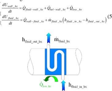
3.2.2 Ambient and cold temperature heat exchangers
The cold heat exchanger of the refrigerator as well as the two heat exchangers at intermediate temperature (Fig. 5) transfer on one side with the
helium
(
Qhel wall _ hx−)
and on the other with a heattransfer fluid
(
Qfluid wall _ hx−)
. The cold one issubmitted to heat transfer with surroundings
(
Qloss _ hx)
while such an exchange is neglectedfor the other ones because of the low temperature difference between these exchangers cooled by water and ambient air. Applying the first law to the wall and to the heat transfer fluid of these elements gives:
(
)
wall _ hx
fluid wall _ hx hel wall _ hx loss _ hx fluid _ hx
wall fluid _ hx fluid _ hx fluid _ in _ hx fluid _ out _ hx
dU Q Q Q dt dU Q m h h dt − − − = + + = + − (5)
Fig. 5. Heat fluxes in the three helium/heat transfer fluid heat exchangers
The heat flux between the exchanger walls and the heat transfer fluids are considered as convective ones. The heat exchange coefficients
and the pressure drops inside the exchanger are calculated thanks to a correlation for a fluid flowing across a bank of tubes [32].
Each equation relative to the exchanger walls has
a term of transfer with helium
(
Qhel wall _ hx−)
. Astationary thermoacoustic model (CRISTA
software) is used to determine these heat fluxes at each computation time step of the quasi-stationary model [33].
3.3. The cold loop and cold thermal energy storage
The cold loop is mainly composed of an electrical resistance simulating the thermal loads, a pump, a cold thermal storage and flow pipes. In order to
simplify the loop model, the following
assumptions are made:
- The fluid is incompressible and nondilatable; - Kinetic and potential energy changes are
negligible;
- Heat transfer by conduction is neglected in the heat transfer fluid.
3.3.1. Flow pipes
The flow pipes insure the connection between elements. For this model, only the two longer pipes are considered (between the pump and the cold exchanger and between the cold exchanger and the cool storage). The other ones are considered too short to influence the dynamic of the system.
The followings assumptions are made to establish the model of these elements (Eq. 6):
- The pipes are adiabatic;
- The pipe walls are considered as an equivalent mass of fluid.
Taking into account these hypotheses, the energy balance gives:
(
)
fluid wall _ pipe
fluid _ cold _ loop fluid _ in _ pipe fluid _ out _ pipe dU
m h h
dt
+ = −
(6)
3.3.2. Circulating pump and electrical fluid circulation heater
The fluid and the element weight of these two devices is considered too low to impact the dynamic behaviour of the experimental plant so that no time variation of the internal energy of these elements has been considered here. They are also considered adiabatic.
Applying the first law to the heat transfer fluid gives:
6
(
)
0=Qheater+mfluid _ cold _ loop hfluid _ in _ heater−hfluid _ out _ heater
(7)
Where Qheater, is the heating power supplied by
the electrical heater.
The energy balance of the fluid inside the circulating pump is expressed by:
(
)
0
.
pump fluid _ cold _ loop fluid _ in _ pump fluid _ out _ pump
W m h h
= + −
(8)
Where W. pump, is the pump mechanical power.
3.3.3. The cool thermal energy storage
The model which has been already described in detail in a previous paper by Bédécarrats et al. [34], considers the aspects of both the surrounding heat transfer fluid and the phase change material packed inside the nodules in the charge mode as well as in the discharge mode.
Fig. 6. Tank control volume
Only the main hypotheses and equations are presented here with a special adaptation to the selected configuration.
In order to simplify the physical model of the latent heat storage and according to our experience [29], the following main assumptions are made:
- The tank is vertical with flow from the bottom
to the top for the both charge mode and the
discharge mode and the temperature variation of the fluid occurs only along the axial direction;
- The tank is adiabatic;
- Considering the nodules, the energy flux
transferred is proportional to the temperature difference between the fluid and the interior of the spherical nodule and supercooling phenomenon is taken into account;
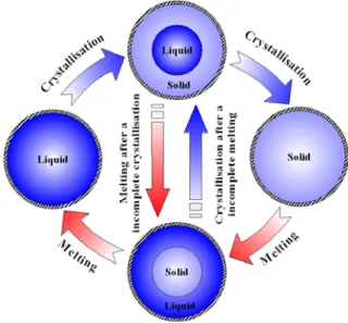
Fig. 7. State of nodule and way of crystallisation and melting
To take into account the temperature gradient inside the tank, this later is divided in several control volumes according to the height (Fig. 6). The energy balances in transient state in each control volume for the heat transfer fluid and each spherical nodule i are:
(
_ _)
,1
nod
N fluid
fluid fluid in fluid out nod fluid i i dU m h h Q dt = − = − + ∑ (9) , , , nod i nod i
nod nod fluid i
dU du m Q dt = dt = − (10) With
(
)
(
)
(
)
(
)
(
)
, , , , , , , v 1 v 1 0 1 v v 0ref PCM solid nod i ref nod i nod i ref PCM solid melt ref nod i nod i
ref PCM solid melt ref PCM liquid nod i ref nod i
u C T T if x u u C T T x L if x u C T T L C T T if x + − = = + − + − < < + − + + − = (11)
Where xnod,i is the solid fraction of the PCM in the
nodule.
Even if the heat transfer fluid temperature is considered uniform in each tank layer, all the
nodules of each layer do not simultaneously
crystallise at the melting temperature Tmelt during
cooling because of the supercooling and the erratic character of the crystallisation. The nodules can thus be found in different states (non-crystallised,
7 entirely or partly crystallised) in the storage tank
(Fig. 7). The number of new crystallisations and the corresponding fluxes can be calculated at each step time t applying the nucleation laws developed by Bédécarrats et al. [34].
Considering a nodule of inner radius rint (Fig. 8),
uniform cooling of its surface will result in a spherically symmetric crystallization front, r =
rinterface is the inner radius of solid PCM,
propagating inwards from r = rint with liquid at
Tmelt for 0 ≤ r ≤ rinterface and solid for rinterface≤ r ≤
rint. Assuming constant thermal properties in each
phase, the steady-state solution of the heat
conduction in the solid phase has the form (TPCM
solid is the temperature in the solid PCM):
int
1
1 1
interface PCM solid melt fluid melt
PCM solid interface PCM solid PCM solid interface
env ext ext env ext
r r T T T T k r k k r k r α r k r − = + − − + − + (12)
Fig. 8. Melting (left) and crystallisation (right) phenomenon inside a nodule
The flux continuity at the interface leads to:
, 2
4
interface
PCM solid nod fluid i PCMsolid interface r r T Q k r πr − = ∂ − = ∂ (13) When no phase change occurs in the nodule (i.e. all the nodule are filled with liquid or solid only), is determined considering a uniform PCM temperature. The heat transfer coefficient between the nodule and the fluid is determined by a correlation proposed by Bédécarrats et al. [35] and so depends on the flow rate and on the fluid temperature.
Supercooling occurs only upon crystallisation but
never upon melting that takes place at Tmelt.
According to a simplifying assumption, the melting-front is considered to be concentric (Fig.
8) and equations for are equivalent to
those for crystallisation. According to Fukusako et
al. work [36], during the melting process, natural
convection and conduction heat transfer are taken into account through the definition of an apparent thermal conductivity.
3.4 Performance criterions
To evaluate the performance of the solar driven thermoacoustic refrigerator coupled with the cold latent storage, two performance criterions are introduced:
- The solar driven thermoacoustic refrigerator
Coefficient Of Performance (COPmachine),
defined as the ratio of the frigorific effect produced by the refrigerator to the solar absorbed energy. fluid wall _ cr machine sol_modul Q .dt COP Q .dt − = ∫ ∫ (14)
- The time availability ratio (τavailability), defined
as the ratio of the time when the cooling power demand is satisfied to the total time of simulation.
availability
time when demand is satisfied total time
τ =
(15)
4. Results and discussion
4.1 Simulation conditions
From the model described in the previous section, several numerical simulations have been carried out to analyse the transient behaviour of the prototype.
For these simulations, a constant ambient temperature of 20 °C has been considered. The used solar radiation conditions are the Direct Normal Irradiance (DNI) measured during July 2006 by PROMES laboratory at Odeillo (South of France) (Fig. 9A), where the prototype will be tested.
The prototype design is not totally completed, so, currently accurate data on the geometric characteristics of all elements are not yet available. However, to predict the future performance of the prototype and to guide the machine design, simulations have been managed considering the order of magnitude for missing data. The main parameters that have been considered for these simulations are summarised in Table 1.
nod fluid
Q −
nod fluid
8 To control and to manage the whole machine, two
regulation systems are used; one to control the maximal temperature of the hot heat exchanger of the thermoacoustic prime mover and the second to regulate the minimum temperature of the cold exchanger of the refrigerator. These two temperatures are regulated with the solar flux modulator. The maximal allowed temperature for the hot exchanger has been set for these simulations to 600 °C and the minimum temperature for the cold one has been fixed to -35 °C. To cool down the cold loop and begin storing in the tank, the heater is let off during the first 30 simulation hours whatever temperature conditions. The PCM has been chosen among available commercial water-salt eutectic solution [37] to be able to change of phase in the range of temperature between -20 °C and -35 °C. These two temperatures correspond to the cold consumption temperature and the minimal temperature of the cold exchanger of the refrigerator. The used PCM is SN.26 from Cristopia company. This commercial PCM is a water solution at the eutectic concentration. The thermophysical properties of the PCM are supposed constant (Tab. 1). This PCM is considered as a perfect eutectic solution. So, the phase change process occurs without segregation
and the phase change process is the same as a pure component with a melting temperature constant [14].
For the calculation of the time availability ratio
(τavailability, see equation 15), the cooling demand is
considered satisfied when the system can supply a cooling power of 400 W at a temperature equal or lower than -20 °C.
4.2. Behaviour study and analysis of energy use
In the following section, the transient behaviour of the solar driven thermoacoustic refrigerator coupled to a latent cold storage is analyzed. Initially, the whole system is at ambient temperature and the PCM in the storage tank is totally melted. During the first seven simulated hours (corresponding to the night), there is no solar irradiance, so the machine remains at initial conditions (Fig. 9A).
When the sun rises, the first solar rays impact the solar absorber, the DNI increases rapidly, thereby increasing the temperature of the hot exchanger (Fig. 9A). The thermoacoustic effect in the wave generator is a threshold effect: the engine starts when a sufficient temperature difference is achieved and maintained between the hot source
Table1 Main simulation parameters (*:estimated)
Solar concentrator aperture area (m²) 14 Tank volume (m3) 0,2
Shadow area on the concentrator (m²) 3,5 Mass flow rate (kg.s-1) 0,1
Reflectivity of the concentrator 0,9 PCM melting temperature (°C) [37, 38] -26,2
Cavity orifice diameter (m) 0,1 PCM latent heat of fusion (kJ.kg-1) [38] 260
Hot heat exchanger mass (kg) 30* Specific heat of solid PCM (kJ.kg-1.K-1) 2
Ambient heat exchangers mass (kg) 5* Specific heat of liquid PCM (kJ.kg-1.K-1) 3,3
Cold heat exchanger mass (kg) 5* Thermal conductivity of solid PCM (W.m-1.K-1) 2,4
Electrical power of the heater (W) 400
Apparent thermal conductivity of liquid PCM during
melting (W.m-1.K-1) [34] 1,1
and the cold source. According to the stationary
simulation results of the thermoacoustic machine,
wave generation begins when a minimum temperature difference of 300 °C is achieved. Since the amount of heat entering the system is quite high and as the weight of heat exchanger is relatively low, the cold production starts relatively rapidly after the sun has risen. A change in the temperature shape is observed in fig. 9A at
approximately 320 °C when heat begins being consumed by the thermoacoustic cycle. At the very beginning, the refrigeration part is still at initial conditions and the cooling capacity rises sharply, up to 2000 W (Fig. 9C). This cooling effect lowers the temperature of the heat transfer fluid that flows in the cold loop and thus lowers the storage tank temperature (Fig. 9B). The maximal hot exchanger temperature has been set
9
Fig 9. DNI and temperature evolution of the hot heat exchanger of the prime mover (A); solid fraction in the storage tank and temperature evolution of the heat transfer fluid at the storage tank inlet and outlet (B), instantaneous cold power and consumption power (C); versus time
to 600 °C. When it reaches this temperature (about 10 h after the simulation has been started) the solar flux modulator begins to hide a part of the solar concentrated flux to modulate the absorbed solar flux and to maintain the hot exchanger temperature. This temperature control has the consequence to reduce the amount of heat entering the system and then the cold production. Under the cooling effect, the fluid temperature at the storage tank input reaches a temperature sufficiently low to initiate the crystallisation of the PCM in the nodules. Because of the supercooling effect and of the thermal resistances between the fluid and the PCM, the first nodule crystallisation occurs when the fluid temperature at the storage tank inlet is about 5 °C lower than the PCM
melting temperature (Tmelt = -26.2 °C) (Fig.
9B).After about 15 h and certainly due to sudden
clouds, the DNI drops down sharply to become equal to zero. Without any solar irradiance and because of the heat consumed by the acoustic power cycle and of heat losses, the temperature of the hot exchanger of the generator decreases rapidly. The critical difference of temperature between the hot and the cold heat exchanger of the prime mover is quickly reached and the engine stops. Due to the heat exchanges between the nodules under crystallisation and the circulating fluid, even if the refrigerator is off, the solid fraction of the PCM increases until the temperature equilibrium between the fluid and the nodules is reached. During the time without cold production, the temperature of the hot exchanger continues to decrease due to heat losses. Whereas the temperatures of the cold loop elements and the storage tank solid fraction remain constant at the
10 melting temperature of the PCM and 10 %. Thirty
hours after the beginning of the simulation, the electrical fluid heater is turned on and supplies a constant power (Fig. 9C). The heat power injected in the cold loop increases the temperature of the circulating fluid, a part of the latent heat which has been stored in the tank is consumed by melting of the solid PCM.
At the beginning of the second day, the temperature of the prime mover hot exchanger is only 30 °C and is heated up as the sun rises. Consequently the cold power increases quickly to reach 1200 W before slightly decreasing under the combined effect of the regulation of the hot temperature and the decrease of the fluid temperature in the cold loop. Even if the refrigerator continues to pump heat from the circulating fluid, when the solid fraction is lower than 60 %, the crystallisation of the PCM maintains the temperature of the latter close to -31 °C at the tank inlet and -28 °C at the outlet. When the solid fraction is high, the solid layers in the nodules become thick and the thermal resistance between the latter and the heat transfer fluid increases. Due to this phenomenon, the fluid temperature and the cold power decrease. During the sunny period of the second day, a part of the cooling effect is directly consumed by the frigorific loads and the other part is stored as latent heat in the storage tank. The sharply solar irradiation variations at the end of this day imply quite rapid variations of the heat exchanger temperature and of the frigorific power. When the thermoacoustic machine stops due to the lack of solar radiation at 46 h, almost 100 % of the PCM is crystallised.
During the following night, a part of the cold which has been stored as latent heat is consumed by melting of the PCM to supply the frigorific load. During the nodule melting process (Fig. 7), the liquid layer at the periphery of the solid centre growths and increases the thermal resistance between the nodule and the circulating fluid. This phenomenon is characterised by a slightly increase in the circulating fluid temperature during the discharge process.
At the beginning of the third day, 62 % of the PCM are still crystallised. So, a large part of the nodules are still filled with both solid and liquid phase at the melting temperature. Thereby, these nodules are not affected by the supercooling effect and the storage charge is managed by a fluid at
higher temperature than the previous day. Under the frigorific production, the PCM is quickly totally crystallised. The latent storage is full and the frigorific effect is then stored as sensible heat; lowering the storage tank temperature. Globally, during the third day, the produced cold effect has not balanced the consumed one and at the end of this day, the solid fraction is lower than that at its beginning.
The solar irradiance of the fourth day is quite high with however a three hours period of low irradiance in the middle of the day. Despite this, all along the day, the cold power is higher than the consumed one (Fig. 9C). As during the previous day, the PCM is rapidly totally crystallised. Due to the large amount of produced frigorific effect, the temperature of the cold loop decreases to reach the regulating temperature of the cold exchanger of the refrigerator (-35 °C). When this temperature is reached, the solar flux modulator begins to hide a part of the solar concentrated flux. Therefore the frigorific power is reduced to maintain the cold exchanger at the regulated temperature. During this production period, a large amount of cold energy has been stored and at its end, the PCM is totally crystallised and the circulating fluid is at a temperature lower than -34 °C.
The sunny periods of the three last days (the fifth, sixth and seven one) are quite short and chaotic with numerous sudden changes in the solar irradiance. Due to these variations, during these three days, the thermoacoustic machine works quasi exclusively in transient mode with high and quick temperature and power fluctuations. The frigorific effect produced during this whole period does not balance the consumed one and the energy that has been stored in the tank is used to supply the frigorific load. At the end of the sunny term of the seventh simulation day, the solid fraction is less than 85 %.
When the simulation ends after seven real solar irradiance days, the thermoacoustic machine is turned off, the circulating fluid temperature of the cold loop is between -24 °C and -25 °C, and the PCM in the storage tank is partially crystallised (solid fraction is less than 65 %).
To avoid the influence of initial conditions and to realize the energy analysis of the whole system with starting and final conditions almost equivalent, the studied period begins when the heater is turned on (thirty hours after the simulation starts) and ends at the end of the week.
11 On an energetic point of view, during this period,
the solar concentrator has collected 576 kWh of solar energy and 280 kWh have been absorbed by the receiver cavity. The difference between the collected energy and the absorbed one is mainly caused by the temperature regulation of the hot and cold heat exchanger with the solar flux modulator. It can hide more than 60 % of the solar concentrated flux when the solar irradiance is high. The thermoacoustic machine has produced, during this period, a frigorific effect of 60 kWh.
The machine Coefficient Of Performance
(COPmachine) is equal to 0.21 and the time
availability ratio (τavailability) reaches 100 %. It
means that under these solar radiation conditions and this design, the prototype is capable to supply without interruption the thermal load under the specific working conditions (400 W at -20 °C).
5. Discussion/Conclusion
A model of a solar driven thermoacoustic cooler prototype coupled to a cold storage using encapsulated PCM, has been developed.
Fig 10. Time availability ration and Coefficient Of Performance of the solar thermoacoutic refrigerator (A), solid fraction in the storage tank versus time (B), for different volumes of the storage tank
Simulations have been carried out considering an entire week of real solar irradiation. As the prototype design is not fully completed, a realistic order of magnitude of missing data has been considered. The PCM characteristics that have been chosen correspond to commercial available material. The transient behaviour of the prototype has been described and its energetic performances
have been analysed. The storage tank has a high thermal inertia compared to the other machine elements, the transient behaviours and thus the performances of the entire system are widely impacted by the storage tank state. In the present simulation, the cold storage volume has been set
to 0.2 m3. With this storage design, the prototype
is able to supply continuously 400 W at maximum -20 °C. However, during the day with high solar irradiation, the PCM is rapidly totally crystallised and the temperature of the cold loop reaches very low temperature (close to -35 °C). This low working temperature affects the performance of the thermoacoustic machine by lowering its Coefficient Of Performance. During the studied
period, COPmachine and τavailability reach respectively
21 % and 100 %.
As described in the previous section, the model is quite complex with various parameters, some relative to the solar collector system, others to the thermoacoustic cycle and finally some of them to the storage. The work that is being done now is to maximise both the availability and the COP while lowering the size (cost) of the whole system. Since one of our main objectives is now to build a prototype, other simulations have been done, considering the same conditions with a lower
storage volume equal to 0.1 m3 and a higher one
of 0.3 m3. The results are presented in Fig. 10.
With the lowest value, the prototype time
availability ratio (τavailability) is less than 85 % (Fig.
10A). It means that during 15 % of the studied period, the prototype is not able to supply the frigorific load under the desired power and temperature conditions. Considering the largest volume, as for the presented case, the time availability ratio remains equal to 100 %. Thank to its large storing capacity, this tank is never totally crystallised and the minimum cold working temperature of the frigorific machine is higher than the one of the presented case (Fig. 10B). However, with this storage design, the Coefficient Of Performance of the prototype reaches only 0.22 (Fig. 10A). Under the considered simulation conditions, the very low performance gain observed with the largest storage tank cannot justify the increase of the storage volume.
The developed model has permitted to determine the future performances of the prototype but also to choose the best configuration of the storage tank, which has to be adapted to the loads. The prototype is under construction and experiments
12 will be carried out next year. The simulation
results will be compared to the experimental ones in order to complete and/or to validate the model.
Acknowledgments
This work was carried out within the framework of the TACSOL project. It is funded by the ANR
PRECODD. We would like to thank our project partners, A. Betrancourt (Hekyom), E. Chabut (Hekyom), Cordillet (PROMES), P. Duthil (IPNO), M.X. François (Hekyom), T. Le Polles (Hekyom), G. Olalde (PROMES), M. Pierens (IPNO) and J.P. Thermeau (IPNO), for their help.
Nomenclature
A area, m²
Cv specific heat capacity, J kg-1 K-1
COP Coefficient Of Performance
DNI Direct Normal Irradiation, W m-2
h specific enthalpy, J kg-1
k thermal conductivity, W m-1 K-1
L latent heat of the PCM, J kg-1
.
m mass flow rate, kg s-1
N number of nodules in the tank layer
.
Q heat flux, W
r radius, m
t time, s
T temperature, K
u specific internal energy, J kg-1
U internal energy, J
x solid fraction of PCM
Greek symbols
α convective heat transfer coefficient, W
m-2 K-1
ε emissivity
χ reflectivity of the concentrator
σ Stefan–Boltzmann constant, W m-2 K-4
Subscripts and superscripts
amb ambient
cavity solar receiver cavity
collector solar collector
cr cold exchanger of the refrigerator
env nodules envelope
ext external
fluid heat transfer fluid
hg hot exchanger of the generator
hel helium
hx heat exchanger
in input
int internal
interface interface liquid/solid of the PCM
liquid liquid phase of the PCM
loss thermal losses
melt melting of the PCM
modul modulated or solar flux modulator
nod nodule
or orifice
out output
PCM Phase Change Material
ref reference
reflect reflected
sol solar
solid solid phase of the PCM
wall exchanger or pipe wall
References
[1] J. M. Calm, Emissions and environmental impacts from air-conditioning and refrigeration systems, Int. J. of Refrig. 25 (2002) 293-305.
[2] J. M. Calm, The next generation of
refrigerants – Historical review,
considerations, and outlook, Int. J. of Refrig. 31 (2008) 1123-1133.
[3] D. S. Kim, C. A. Infante Ferreira, Solar refrigeration options - a state-of-the-art review, Int. J. of Refrig. 31 (2008) 3-15. [4] F. Zink, J. S. Vipperman, et L. A. Schaefer,
Environmental motivation to switch to thermoacoustic refrigeration, Appl. Therm. Eng.30 (2010) 119-126.
[5] J. J. Wollan, G. W. Swift, S. Backhaus, D. L. Gardner, Development of a thermoacoustic natural gas liquefier, presented at the AIChE New Orleans Meeting, New Orleans, LA, March 11-14, 2002.
[6] G. Yu, E. Luo, W. Dai, Advances in a 300 Hz thermoacoustic cooler system working within liquid nitrogen temperature range, Cryogenics 50 (2010) 472-475.
[7] J. Y. Hu, E. C. Luo, S. F. Li, B. Yu, W. Dai, Heat-driven thermoacoustic cryocooler operating at liquid hydrogen temperature with a unique coupler, J. of Appl Phys. 103 (2008) 1-8.
[8] M. E. Poese, R. W. M. Smith, S. L. Garrett,
13 Thermoacoustic refrigeration for ice cream
sales, in Proceedings of 6th IIR Gustav Lorentzen Conference, Glasgow, UK, 2004. [9] J. A. Adeff, T. J. Hofler, Design and
construction of a solar-powdered, thermoacoustically driven, thermoacoustic refrigerator, The J. of the Acoust. Soc of Am.107 (2000) 37-42.
[10] R. L Chen, Design, construction, and measurement of a large solar powered thermoacoustic cooler, PhD thesis, The Pennsylvania State University, USA, 2001. [11] Z. Wu, W. Dai, M. Man, E. Luo, A
solar-powered traveling-wave thermoacoustic electricity generator, Solar Energy 86 (2012) 2376–2382.
[12] C. Shen, Y. He, Y. Li, H. Ke, D. Zhang, Y.
Liu, Performance of solar powered
thermoacoustic engine at different tilted angles, Appl. Therm. Eng. 29 (2009) 2745-2756.
[13] I. Dincer, M. A. Rosen, Thermal Energy Storage: Systems and Applications. Second Edition, John Wiley & Sons, Ltd, Chichester, UK, 2010.
[14] A. Sharma, V. V. Tyagi, C. R. Chen, D. Buddhi, Review on thermal energy storage with phase change materials and applications, Renew. and Sustain. Energy Rev. 13 (2009) 318-345.
[15] B. Gin, M. M. Farid, P. K. Bansal. Effect of door opening and defrost cycle on a freezer
with phase change panels, Energy
Conversion and Management 51 (2010) 2698-2706.
[16] A. C. Trapp, F. Zink, O. A. Prokopyev, L. Schaefer, Thermoacoustic heat engine modeling and design optimization, Appl. Therm. Eng. 31 (2011) 2518-2528.
[17] D. S. Antao, B. Farouk, Experimental and numerical investigations of an orifice type cryogenic pulse tube refrigerator, Appl. Therm. Eng. 50 (2013) 112-123.
[18] H-B. Ke, Y-W. Liu, Y-L. He, Y. Wang, J. Huang, Numerical simulation and parameter optimization of thermo-acoustic refrigerator driven at large amplitude, Cryogenics 50 (2010) 28–35.
[19] A. S. Worlikar, O.M. Knio, Numerical Simulation of a Thermoacoustic Refrigerator: I. Unsteady Adiabatic Flow
around the Stack, J. of Comput. Phys., 127 (1996) 424–451.
[20] A. S. Worlikar, O.M. Knio, R. Kleiny, Numerical Simulation of a Thermoacoustic Refrigerator: II. Stratified Flow around the Stack, J. of Comput. Phys., 144 (1998) 299– 324.
[21] D. Marx, P. Blanc-Benon, Numerical Simulation of Stack–Heat Exchangers Coupling in a Thermoacoustic Refrigerator, AIAA J. 42, No. 7 (2004) 1338-1347.
[22] Los Alamos National Laboratory, www.lanl.gov/thermoacoustics/DeltaEC.htm l, consulted the 23 of November 2012. [23] T. J. Hofler, E. Purdy, S. Curtis, A graphical
software application for design and simulation in thermoacoustic research (DSTAR), J. Acoust. Soc. Am. 108 (2000) 2554-2554.
[24] A. Betrancourt, T.L. Polles, G. Defresne, D. Baltean-Charles, P. Duthil, J.P. Thermeau, M. X. François, Experimental validations of a new thermoacoustic simulation software CRISTA, The J. of the Acoust. Soc of Am.123 (2008) 3707.
[25] D. G. Holmberg, G. S. Chen, H. T. Lin, A. M. Wo, Thermal modeling and performance analysis of a thermoacoustic refrigerator, J. Acoust. Soc. Am. 114 (2003) 782-791.
[26] H. Babaei, K. Siddiqui, Design and optimization of thermoacoustic devices, Energy Conversion and Management 49 (2008) 3585–3598.
[27] F. Nepveu, A. Ferrière, F. Bataille, Thermal model of a dish/Stirling systems, Sol. Energy 83 (2009) 81-89.
[28] S. Cordillet, P. Duthil, F. Nepveu, T. Le Polles, G. Olalde, A. Salome, J.-P. Thermeau, Theoretical proof of concept of an optimal solar receiver to produce low-temperature (-40 °C) cooling using a thermoacoustic tri-thermal machine, in : Proceeding of SolarPACES 2010, Perpignan, France, September 21-24, 2010, lecture number 229.
[29] S. Cordillet, P. Duthil, E. Guillot, G. Olalde, C. Gueymard, Potential effects of rapid incident flux variations on the design of a solar thermoacoustic receiver, in :
Proceeding of SolarPACES 2010,
Perpignan, France, September 21-24, 2010, poster number 230.
14 [30] G. Swift, Thermoacoustics: a unifying
perspective for some engines and refrigerators. Acoust. Soc. of Am. through the Am. Inst. of Phys, Melville NY, 2002. ISBN: 9780735400658.
[31] J. P. Bédécarrats, J. Castaing-Lasvignottes, F. Strub, J. P. Dumas, Study of a phase change energy storage using spherical capsules. Part I: Experimental results, Energy Convers. and Manag. 50 (2009) 2527-2536.
[32] Y. A. Çengel, Heat transfer: a practical approach, second ed., McGraw-Hill, New York, USA, 2003. ISBN: 9780072458930. [33] M. Perier-Muzet, J. Castaing-Lasvignottes,
P. Stouffs, P. Duthil, J.-P. Thermeau, G. Olalde, S. Cordillet, M.-X. François, Modelling and dynamic simulation of a thermoacoustic refrigerator, in: Proceedings of Congrès Français de Thermique 2010, Le Touquet, 2010, vol. 2, p. 851-856 (in French).
[34] J. P. Bédécarrats, J. Castaing-Lasvignottes, F. Strub, J. P. Dumas, Study of a phase
change energy storage using spherical capsules. Part II: Numerical modelling, Energy Convers. and Manag., 50 (2009) 2537-2546.
[35] J.P. Bedecarrats, F. Strub, B. Falcon,J.P. Dumas, Phase-change thermal energy storage using spherical capsules: performance of a test plant, Int. J. Refrig., 19 (1996) 187–196.
[36] S. Fukusako et M. Yamada, Recent advances in research on melting heat transfer problems, in: Proceedings of the 10th Int. Heat Transfer Conf., Brighton, UK, 1994, 313-331.
[37] Cristopia,
www.cristopia.com/cristopia/indexCristopia. html, consulted the 22 of July 2012.
[38] B. Zalba, J. M. Marin, L. F. Cabeza,H. Mehling, Review on thermal energy storage with phase change: materials, heat transfer analysis and applications, Appl. Therm. Eng. 23 (2003) 251–283.