Decision Algorithms for Unmanned Underwater
Vehicles during Offensive Operations
Tyler
B.
Smith
B
.S., Operations Research
United States Military Academy
(1996)
Submitted to the Department of Civil and Environmental Engineering
in partial fulfillment of the requirements for the degree o
Masters of Science in Pansportation
at the
MASSACHUSETTS INSTITUTE
OF
TECHNOLOGY
(
LIBRARIES
I
June 2006
@
Massachusetts Institute of Technology 2006. All rights reserved.
~ R C H M S
...
.
Author
.~:'y.-.
.
:-.r: :.-.
..
.-.
.
Department of Civil and Environment a1 Engineering
May 12, 2006
...
Certified by
...
.; .-.
.,.
* l ? - - - -- -
-
Margaret
F.
Nervegna
Charles Stark Draper Laboratory
Technical Su~ervisor
Certified by
...
...
3
.
/
r . . .-.t(:.-if
Professor Cynthia Barnhart
Civil and Environment a1 Engineering
A#"
~ h ~ i s
Supervisor
Accepted
by.
...
.r.. ~ w . ~ . . ~ ~ ~
'L$d
. . .
. .
Professor Andr
J:
Whittle
Decision Algorithms for Unmanned Underwater Vehicles during
Offensive Operations
by
Tyler
B.
Smith
Submitted to the Department of Civil and Environment a1 Engineering on May 12, 2006, in partial fulfillment of the
requirements for the degree of Masters of Science in Transportation
Abstract
The field of research involving autonomous vehicles has expanded greatly over the past decade. This thesis addresses the case of a system of Unmanned Underwater Vehicles (UUVs) operating in littoral areas in an offensive capacity. A series of complementary algorithms were designed to collect information about an enemy vessell, and subsequently use this information to both select and move to a prefered intercept location that maximizes the opportunity to both re-acquire and destroy an enemy vessel. Additionally, within the context of a specifically designed simulation, key parameter changes were analyzed to determine their effectiveness to improve the system's performance as measured by four measures of effectiveness. A methodology was also designed to optimize the location of the engaging UUVs t o maximize their effectiveness, and capitalize on the enemy movement within the operational area. Results are presented for both original locations and optimized locations, and initial findings provide insight into the effectiveness of the designed algorithms and statistical inference of these key parameter changes.
Technical Supervisor: Margaret
F.
Nervegna Title: Charles Stark Draper LaboratoryThesis Supervisor: Professor Cynthia Barnhart Title: Civil and Environmental Engineering
Acknowledgments
There are many to whom I owe a debt of gratitude for the success and completion of this thesis.
I must first and foremost thank my wife Tiffany for her continued support throughout this process. She has been making personal sacrifices our entire marriage, and she has done so with a smile and huge heart. Our time here at MIT will always be remembered by the birth of McKenzie Claire. Tiffany, you remain an inspiration to me, and I hope you never forget how much I love you as we continue through this crazy life.
I thank the Army, Draper Laboratory, and MIT for giving me this educational opportu- nity that will forever enrich my life and career. Dr. Michael Ricard and Margaret Nervegna, my Draper advisors; I can never thank you enough for your exceptional guidance and ex- pertise shared during my time at Draper. Your dedication to the research and fundamentals of education are inspiring, and
I
can't imagine going through this process without your assistance.I
am very grateful to Dr. Cynthia Barnhart, my MIT thesis advisor, for her diligence to continually meet with me, which motivated my continual progress with this research. Her remarkable enthusiasm for research is truly inspirational, and I am truly a better person for having worked with her.Contents
1 Introduction 15. . .
1.1 Problem Motivation 16. . .
1.2 Problem Statement 17. . .
1.3 Contributions and Organization of Thesis 18
2
UUV Role in Naval Operations
2 1. . .
2.1 UUV Development in US Navy 23
. . .
2.2 Current UUV Operations 27
. . .
2.2.1 Civilian Operations 27
. . .
2.2.2 Military Operations 28
. . .
2.3 Current UUV Challenges 30
3 Area of Operations 33
. . .
3.1 Area of Operations 33
. . .
3.1.1 Bathymetric data for the area of operations 34. . .
3.1.2 Shipping Lanes 35
. . .
3.1.3 Narraganset Bay Specific Lanes 35
. . .
3.2 Digital Map 37 4 Simulation Vehicles 41. . .
4.1 Enemy Vehicles 41 . . . 4.1.1 Foundational Assumptions 414.1.2 Three Types of Simulated Vehicles . . . 4.1.3 Enemy Vehicle 1 : Cargo Vessel . . . . . . 4.1.4 Enemy Vehicle 2: Ocean Surveillance Vessel
. . . 4.1.5 Enemy Vehicle 3: Frigate
4.2 Enemy Movement Assumptions . . . 4.2.1 Route . . . 4.2.2 Wayp0int.s . . . 4.2.3 Speed . . .
. . . 4.2.4 Calculate the Exact Enemy Route
. . . 4.3 Friendly Mission Statement
4.4 Friendly Vehicles . . . . . . 4.4.1 Foundational Assumpt~ions
. . . 4.4.2 Hunter UUV hlission Specifications
. . . 4.4.3 Killer UUV Mission Specifications
5 Simulation Design and Key Algorithms
. . . 5.1 User-Defined Simulation Para.met,ers
. . . 5.2 Simulation Initialization
5.3 Determine Enemy Location and Speed . . . 5.3.1 So~lar discussion . . .
. . . 5.3.2 Enemy Location and Speed Algorithms
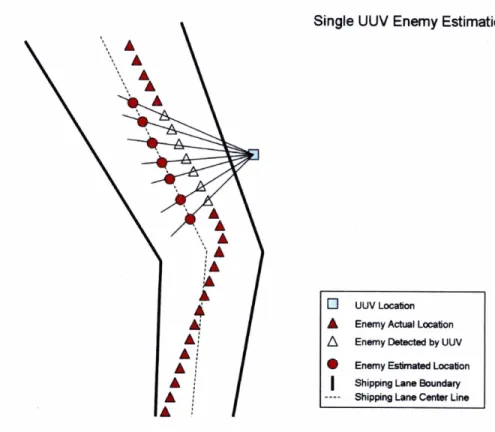
5.3.3 Single-Ship Bearing only Calculation without own-ship movement
.
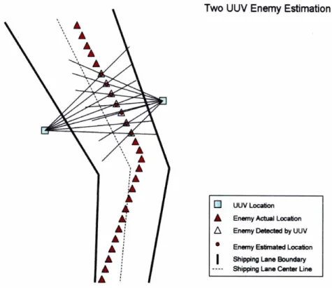
. 5.3.4 Multiple-UUV Bearings only Calculation without own-ship movement*. . . 5.3.5 Comparison of Different Calculations
5.3.6 Probability of Routme . . .
5.3.7 Intercept Location . . . 5.3.8 Shortest Path . . . 5.3.9 Enemy Engagement . . .
6
Experimental Design and Initial Results
77. . .
6.1 Experimental Design 77 6.1.1 Examined Parameters . . . 78 6.1.2 Factorial Design. . .
79 6.1.3 Measures of Effectiveness . . . 80. . .
6.2 Statistical Comparison 83 6.3 Numerical Results . . . 876.3.1 Impact on Kill Percentage . . . 87
6.3.2 Impact on Reacquire Percent age
. . .
886.3.3 Impact on Enemy Distance Error
. . .
906.3.4 Impact on Enemy Speed Error
. . .
92. . .
6.3.5 Observations 93 7Optimization of Killer
UUVLocation
95 7.1 Methodology. . .
957.1.1 Establish baseline assumptions . . . 96
7.1.2 Determine feasible intercept points
. . .
967.1.3 Rank order intercept locations
. . .
1027.1.4 Determine feasible UUV start locations . . . 102
7.1.5 Assign value to each start location . . . 104
7.1.6 Choose optimal start locations . . . 105
7.2 Initial results of the optimization
. . .
1067.3 Revised experimental results
. . .
1077.4 Conclusion
. . .
1098
Conclusion
111 8.1 Research Summary . . . 1118.2 Areas for Future Research . . . 112
List
of Figures
2.1 UUV Operations in Iraq . . . 29
3.1 Narraganset Bay Area of Operations . . . 34
3.2 Narraganset Bay Shipping Lanes . . . 36
3.3 Digitized Map with lOOOm grid Int. erval . . . 38
3.4 Digitized Map with 500m grid Interval . . . 38
3.5 Digitized Map with 200m grid Interval . . . 39
. . . 4.1 Cargo Vessel 43 . . . 4.2 Ocean Surveillance Vessel 44 . . . 4.3 Typical Naval Frigate 45 4.4 Enemy Travel through Shipping Lanes . . . 49
5.1 Single Ship Enemy Det. ection . . . 60
5.2 hlult. iple Ship Enemy Detection . . . 62
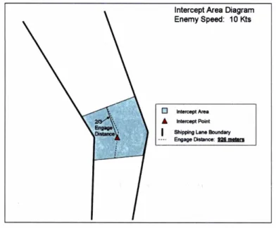
5.3 Intercept Area at 10 knots . . . 67
5.4 Intercept Area at 25 knots . . . 68
7.1 Sensor Coverage Range of Hunter UUVs . . . 97
7.2 Determination of Route A and C latest detection point . . . 98
7.3 Determination of Route B latest detection point . . . 98
7.4 Determination of Route A first feasible intercept point . . . 99
7.6 Determination of Route
C first feasible intercept point
. . . 1007.7 Intercept Area at 25 knots . . . 101
7.8 Optimal Intercept Points for Each Route . . . 101
7.9 Killer UUV start point. s . . . 104
List
of
Tables
. . .
3.1 Narraganset Bay Shipping Lanes 37 3.2 Example of Discrete Map . . . 38
. . .
4.1 Cargo Vessel Specifications 43 4.2 Ocean Surveillance Vessel Specifications . . . 44
. . .
4.3 Frigate Vessel Specifications 45 4.4 Ship Lane Usage . . . 46 4.5 Historical Lane Usage Proportion . . . 46 4.6 Ship Lane Probability . . . 46
. . . 4.7 Initial Speed Distribution 47
5.1 Enemy Estimation Error . . . 64 5.2 Probability of Hit . . . 75
. . .
5.3 Probability of Kill given Hit 75 Factorial Experimental Design . . . 80 Sensor Range Experiments . . . 83
. . .
Weapons Range Experiments 84
. . .
UUV Speed Experiments 84 UUV Torpedo Experiments . . . 84 Proportion Definitions . . . 85 Mean Comparison Definitions . . . 87
. . .
Chapter
1
Introduction
This thesis develops decision algorithms to facilitate unmanned undersea vehicles (UUVs) operating in an offensive capacity. More precisely, this thesis develops and implements decision algorithms that will enable a specially structured team of UUVs to detect, intercept, engage and ultimately dest,roy hostile cont,acts in littoral or shallow water areas. This chapter discusses the problem, the motivation, and t'he importance of UUVs operating in an offensive capacity. The conclusion of this chapter presents a summary of the contributions and an out line of the thesis.
An unmanned undersea vehicle is defined as a self-propelled submersible whose operation is eit,her fully autonomous (pre-programmed or real-time adaptive mission control) or under minimal supervisory control and is un-tethered except for wireless communication links. [l] This research will focus on algorithms that are applicable to offensive operations for UUVs under minimal supervisory control, and un-tet hered. Additionally, within the context of these algorithms, a realistic simulation testbed must be designed and built to measure algorithm success and analyze the contribution of key parameters t,oward improving syst'em performance.
1.1
Problem Motivation
The future of modern warfare is for light nlobile troops t o operate independently in littoral area,s. With the US milit,ary spiraling its capabilities toward sea-based warfare during the first quart,er of the 21st cent,ury and ot,her western forces readying themselves for littoral warfare, t,here is increasing need for a suite of weapons systems t,hat can simultaneously defend both sea-ba,sed asset,s and anlphibious forces. [21] While it is txue that ma,ny recent naval nlissions such as sanction enforcement, interdiction opera-tions, and support to ground forces ashore, suggest a shift from blue water to littoral operations, in fact most naval act,ivity during t,he Cold War took place in littoral areas. 1201 While strategic mobility and operational maneuver a,re stmill inherent strengths for naval forces, care nlust be exercised when operat,ing within the range of land, and magnifies the import,arlce of opera,ting in and coritrolling lit'toral areas of opera,t,ion.
Autonomous Operations (AO), one of twelve future naval capabilit'ies, is the capability to perform militarily useful missions using url~nanned vehicles in dynamic and unstructured environments with greatly reduced neeti for human intervention. The Unit,ed States Navy explores multiple types of UUV mission profiles; but for the purposes of t-his t,hesis, offensive weapon engagements are explored.[l] Key benefits and missions in which UUVs show high pro~riise are:
1. Sensor Deployment: UUVs have the ability to emplace sensors in an excellent po- sitmion in both the vertical and horizont a1 dimensions.
2. Autonomy: The ability of an UUV to operate independently for extended periods creates a force multiplier t,hat. allows manned systems to extend their rea,ch and focus on more difficult, tasks. Reduced costs are also a result when sensors and weapons are operated from smaller platforms like UUVs.
3. Risk: Because UUVs are unmanned, there is a reduced threat t o personnel from a harsh sea or enemy combatants.
4.
Deployability:
UUVs can be designed as flyaway packages or pre-positioned in for- ward areas. They can be launched from a wide variety of platforms including ships, submarines, aircraft, and shore facilities. Also, they do not have to be recovered from the same craft from which they were launched. Recoveries may be delayed or aban- doned because of the extendability created by a UUVs low cost.5.
Environmental Adaptability:
UUVs can operate in a diverse range of environments including deep t o shallow water, foul weather and seas, and tropical or arctic conditionsDue to the complicated nature of these missions and the environments in which they are carried out, there exists a continued need to develop and implement decision systems that can handle untested situations and environments.[5] Although technology and industrial capacity exist, UUV autonomy has yet to reach a level of confidence where they would be permitted to execute complex missions, especially missions involving hostile engagements.
1.2
Problem Statement
The specific problem addressed through this thesis is the development of efficient decision algorithms to allow a system of UUVs t o act in an offensive capacity. Initially, it is as- sumed that a threat vessel is operating in its own harbor, and a system of friendly UUVs has been deployed to locate and engage the threat vessel. However, the system must ac- quire the target, receive permission to engage, and subsequently engage only after receiving appropriate approval; Therefore, a series of complementary algorithms must be developed that can acquire the enemy vessel, detect key information about the threat, and determine a methodology to select and move to a preferred location to intercept the threat vessel.
In the end, a simulation must be developed t o test the decision algorithms, and provide a methodology by which key UUV technological enhancements can be examined.
1.3
Contributions and Organization of Thesis
The contributioris of this thesis are:
Enemy Information. The work in this thesis develops an approach to use shipping lane informa,tion t o accurately estimate information regarding location and speed of potential t.argets. The fundamental idea is tlo assume the enemy vessel is traveling down the center of the lane, and use bearing information gatthered from a detector to calclilate an est,imated locatmion for the t,arget, and subseq~ent~ly infer its operating speed. Additional benefits of this approa,ch include the ability to gather i~iformat~ion about the threat vessel wit-hout requiring complex detector movements that are both difficult to automate, and require t,he use of limited energy stores.
2. Intercept locat ions. The fundament'al approach in this research again uses infor- mation regarding the shipping lanes in a lia,rbor and specifies a preferred intercept location. Rat her t,han a,ttempting t,o int,ercept the threat vessel based on predicted location and time, this research uses the shipping lane concept to intercept the threat at a location that minimizes the area of the shipping lane at the intercept point. This point both increases the opportunity for reacquisition of the target, and minimizes the operational area for t,he threat to avoid t,he impending attack by the UUV.
3. UUV location. The research develops and implements a novel concept for placement of UUVs. Through t,he use of envirol~rnent~al information, the friendly UUVs are po- sitioned in optimal locations that provide a robust opportunity for reacquisition and improves probability of sllccessful engagements.
The remaining portions of this thesis are organized as follows. Chapter 2 explores tohe current state of t.echnology and t,actics for UUVs opera,ting in the military environment.
Chapters 3 and 4 explore t,he select,ed area of operations and the base vehicles that are used in t,he underlying simulation designed to test the algorithms and gain inference on statistical improvement~s t o the system.
Chapter 5 outlines the design of the algorithms and discusses the overall structure of the simulation. The algorithms are discussed in detail, and are presented in a general format to permit their application in any operational area that is similar to the littoral area selected for this simulation.
Chapter 6 explores the experimental design used to compare the parameter changes, examines the st at ist ical met hods selected to numerically compare the varying simulation cases, and presents the initial results of the simulation.
Chapter 7 examines the developed methodology to optimize the location of the UUVs charged with killing the threat vessel, and subsequently presents the new results of the experimental design with the new placement of these "killer" UUVs.
Chapter 8 offers a summary of the research and provides recommendations for future work that could benefit the future of UUVs operating in the offensive role.
Chapter
2
UUV Role in Naval Operations
"Throughout history we have seen that the technology that has given us the best return often was looked at skeptically at the beginning."
Rear Adm. Paul
F.
Sullivan Director -Submarine Warfare DivisionAmong the worlds naval forces, the
U.S.
Navy and Marine Corps are second to none, and at present they have no close competitor. However, the current national security en- vironment places increased demands on the Navy and Marine Corps for increased presence in a larger number of strategically important geographic locations. Addit'ionally, the need exists for a more rapid and flexible response to emerging crises, and for new capabilities to enable decisive victory over determined adversaries employing asymmetric means; defined as a weaker combatant uses nontraditional weapons and strategy in order to obtain a fighting advantage over a stronger opponent.As t,he post-Cold War era has evolved, it has become increasingly clear that many legacy military systems have limited utility in meeting many emerging challenges. As part of the ongoing transformation of the
U.S.
military services, the future Navy and Marine Corps requirements mandate a marked transformation. The environment of the world today reflects increased uncertainty about origins of threats, possible locations of attacks, and the means by which they might be delivered. The term asymmetric threat is now familiar in militaryoperations, arid terrorist act,ions are a frequent occurrence arid constant t,hreat. For naval forces, the classical terms "blue water" t,hreat arid "major threat axis'' no longer hold the significance they once did; the threat environment has moved from the "blue water" to "brown wa,t.er," or lit<t#oral regions, placing emphasis on power projection, force protection, and global expedit'ionary operations in litt,oral areas.
Along wit,h t,his change in emphasis, new capabilities will be required of naval forces in the areas of "iraritime intelligence, surveillance, and reconnaissance (ISR); oceanographic bathy- metric surveys; baattlespace preparation; battlespace awareness; mine warfare; antisubmarine warfare (ASW); specia,l operations and strike support,; surface warfare (including interdic- tion); lit,toral ASW with emphasis on diesel submarines; and base and port security."[2] In turn, the kinds of missions listed above place a premium 011 integrated, persistent ISR;
cornrnand, control, and communications (C3); and distribut,ed. real-time knowledge. The increasing needs arising from the new threats may be alleviated, t o a growing extent, by exploiting the beriefit,~ of technological advances. [3]
One key technology that has emerged over the last two deca,des is t,he unmanned ve- hicle which can perform military functions that are often too dangerous or impossible for manned vehicles. These unmanned vehicles are capable of operating on land, sea or air and have demonst,rated an operational ability to act as a force multiplier in almost all military operat.ions. Several current syst,ems set, the precedent), including t,he Tomahawk, which is an armed unmanned aerial vehicle (UAV); the ADCAP t,orpedo; the Improved Submarine Launched Mobile Mine (ISLMM)
,
and the CAPTOR mine. [2]With these systems in place, t'he United States Navy has placed significant emphasis on the development of UUVs to meet their future operational needs. Speed, covertness, and long standoff could allow a UUV t,o be an effective weapon or weapon platform in a variety of mission scenarios. All else being equal, unmanned vehicles with a high degree of autonomy can potentially reduce trraining, support rapid change in tactics (i.e., capit,alize more rapidly on t,he digital battlefield) , enable reductions in force personnel, and help reduce the logistics f ~ o t ~ p r i n t , t.o name a few advantages. The bottom line is that autjoriomous vehicles will play
a major role in the transformed force.
2.1
UUV
Development in
US
Navy
In June 2002, the United States Navy introduced "Sea Power 21" to guide the US Navy toward a "broadened strategy in which naval forces are fully integrated into global joint operations against regional and trans-national dangers." [2] This document gives Naval oper- ators, technical advisers and future acquisition personnel general guidance about the future Naval vision, and ensures a common picture of growth and focus for the many disparate stakeholders.
Beginning in 1994, the United States Naval Undersea warfare community developed a "UUV Master Plan" to guide the future capabilities and integration of Unmanned Undersea Vehicles into the Navy arsenal and execution of its core competencies. This plan has sub- sequently had two revisions in 2000, and most recently in November, 2004, which followed the "Sea Power 21" framework to ensure on-going UUV development was nested within this overarching framework.
The Navy-approved UUV Master Plan provides a thorough and explicit road map for the development of UUVs, addressing their evolving capabilities, their tactical and strategic concept of operations, and they many technology and engineering issues; including under- water communications, improved sensors, improved navigation, high energy density sources, and improved launch-and-recovery systems. [1]
The "UUV Master Plan" crafted with input from Navy users, stakeholders, Navy labo- ratories, academia, and industry to develop prioritized missions where UUV technology can play a discernible role[l]. The priorities are as follows:
1. Intelligence, Surveillance and Reconnaissance (ISR) : This mission focuses naval resources -
-to gain information about current or future threats through direct or indirect observa- tion. This does not normally include direct action.
2. Mine Countermeasures (MCM): This capability is to find or create operating areas - 23
that are clear of sea mines without requiring manned platforms to enter threa,tening areas.
3. Anti-Submarine lhTarfare (ASW): This ~apabilit~y focuses on preventing a threat from operatirig its Submarine force t o hinder, t,hreaterl or interdict friendly ~perat~ions.
4. Inspect~ion/Identification: This capability focuses on t,he 'bility to reconnoiter areas of concern rapidly for t'hreatening objects or vehicles, and subsequently identify and possibly react t o the threat.
5. Oceanographiy: This capability provides for t,he collectiom of hydrographic and oceano- graphic data in ocean environments. This supports real time operations as well as intelligence preparation of the batt,lefi~ld for future operations.
6. Communication/Navigation Network Nodes
(CK3):
This capability focuses on provid- ing connectivity across multiple platfor~ns, and enabling navigation and secure com- munications to meet any naval requirement,.7. Payload Delivery: This capability focuses on a clandestine method of delivering logis- tics to support mission objectives. An example could be clandestine resupply of CIA ~perat~ives operating in hostile areas.
8. Information Operat,ions (10) : The objective of Information Operations is to "exploit, deceive, det,er and disrupt our enemies" [I].
9. Time Critical St,rike (TCS): This aspect focuses on delivering weapons to a target, using the stealth of the UUV t-o confuse t,he enemy and reduce t,heir react.ion time t80 the normal long-dista,nce cruise missile.
These high priority missions were subsequently grouped under the four Sea Power 21
pillars [2] :
1. Sea Shield: Sea Shield is the concept focused on the protect,ion of national interests by sea-based defense resources. Tradit,ionally, the Xavy has maintained vital sea lines
of communication, protected its own offensive forces, and provided strategic deter- rence through nuclear-armed submarine patrols. Under Sea Shield, the Navy will also project an umbrella of theater air defense ashore, assist in providing ballistic missile defense for the U.S. homeland and for forces in theater, and extend the security of the United States seaward by detecting and intercepting vessels of hostile intent.[3] The aforementioned priorities associated with Sea Shield are:
(a) Mine Countermeasures (b) Anti-Submarine Warfare
(c) Inspect ion/Identificat ion
2. Sea Strike: Sea Strike is a broad concept for projecting precise and persistent offensive power from the sea. According to this concept, networked, autonomous, organic, long- dwell naval sensors, integrated with national and joint systems, will provide persistent intelligence, surveillance, and reconnaissance (ISR), enabling the development of a comprehensive understanding of an adversarys capabilities and vulnerabilities. Closely integrated with these ISR assets will be the capability to strike time-sensitive and moving targets so as to defeat any plausible enemy force.[3] The priorities associated with Sea Strike are:
(a) Information Operations (b) Time Critical Strike
3. Sea Base: As stated in "Sea Power 21," "As enemy access to weapons of mass de- struction grows, and the availability of overseas bases and ports declines, it is com- pelling both militarily and politically t o reduce the vulnerability of U
.S. forces through
expanded use of secure, mobile, networked sea bases." [2] Sea Basing will support ver- satile and flexible power projection, enabling forces up to the size of a Marine Expe- ditionary Brigade (MEB) to move to objectives deep inland. More than a family of platforms afloat, Sea Basing will network platforms among the Expeditionary StrikeGroup (ESG), the Carrier Strike Group (CSG), the i\larit,ime Prepositioning Force
(MPF),
the Combat Logistics Force (CLF), and emerging high-speed sea lift t-ech- nologies. It will ena,ble Marine forces to commence sustainable operations and enable the flow of follow-on forces int.o theat,er and through the sea base, as well as expedit- ing the reconstitution a,nd redeployment of hlarine forces for other missions. [3] The aforementioned priorities associat,ed witah Sea Base are:(a) Payload Delivery
4. ForceNet: FORCEnet is the Chief of Naval Opera,tions (CNOs) vision for enabling riet,work-centric operations for t,he Navy. According t,o the CNO
ADM
Vern Clark, FORCEilet is the "operational construct and architectural framework for naval warfare in the informat ion age, integrating warriors, sensors, command and control, platforms, and weapons into a networked, distributed combat force." [2] While broader in concept than just communications networks, it includes "dynamic, multi-path and survivable networks" among t,he capabilities to be provided.[3] The aforementioned priorities as- sociated with ForceNet are:(a) Intelligence? Surveillance and Reconnaissance (b) Communication/ Navigation Network Nodes
(c) Oceanography
It is within this framework that this thesis examines the UUV capability to perform offensive operations. This document explores decision algorithms that are enhancements to current tactics and fall within both t,he Sea Shield and ForceNET areas of emphasis. However, prior t,o in-dept,h discussion, it is imperative to understand the basic fundament,als of UUVs and explore the current state of technology within this growing community.
2.2
Current
UUV
Operations
The field of UUVs has grown over t,he past 20 years from rudimentary tethered vehicles that execute simple tasks such as ship inspection or oceanic search to today's UUVs that can ut,ilize advanced sensors to search for mines or undersea life. The preponderance of open source UUV development has taken place wit,h civilian applications in mind, and the military development has often been geared t,o capitalize on these adva'nces to improve their operations.
2.2.1 Civilian Operations
For more than two decades, unmanned systems have played a notable role in oceanographic research, deep water commercial applications, and military related missions. In the 1980s, researchers used a tethered UUV t o explore the wreck of the Titanic, nearly 2.5 miles below the ocean surface.[21] More recently, UUVs have helped the oil and gas industries explore the seabed for new energy sources; and aided the military in destroying active underwa- ter mines litt,ering the Persian Gulf floor following the Gulf War. Interest in using UUVs in private industry is growing and internationally, at least a half-dozen firms have begun to commercialize UUV technology developed in university and military lab~rat~ories. Cur- rently, several vehicles are available for sale on the world market, and some developers also offer UUV services to the oil, undersea mining, and submarine cable industries for detailed bottom mapping, surveying and geological exploration. In many applications, the UUV ap- proach costs less than half that of a typical deep towed system covering the same area- and, these vehicles can, and have, explored places t,hat towed systems cannot, such as under the Arctic Ice. Typically, the UUVs offered for commercial services have been relatively small
- generally about 15 feet long and several thousand pounds- and t'hey offer endurance on
2.2.2
Military Operations
The first real auto~lomous underwater vehicle was the MK30 modified torpedo, used in ASW t>raining t o sirnulat,e a submarine's signa,ture. The MK30hlOD 1 init,ially became operational in 1975 with 63 units in fleet service, and the much more advanced MOD2 began evaluations in 1998 with the first units t,o be procured during 2005.[8] The 1994 UUV Program Plan led to t,he development of the Near-term Mine Reconnaissance System (NL;IRS), which was test-ed in 1998 from an oceanographic vessel, conduct.ing deep and shallow watrer surveys for mine countermeasures purposes. A~ldit~ional tests from LOS ANGELES class submarines were c o n d ~ c t ~ e d in t,he same year. NhlRS is fiber-optic controlled, carries a multi-beam search sonar and a side-scan classification sonar, and is launched and recovered via a torpedo tube. NMRS was plagued by a number of significant limit,atnions: poor navigation accuracy, high false-contact ratme, no bathymetry? ant1 additionally it is not fully independent, being tetoher-lirnit,ed. The next generation Long Range Mine Reconnaissance System (LMRS), in development by Boeing, features a 533mm diameter t,orpedo shape, and is fitted with a forward looking search sonar and a side-looking cla,ssification sonar for mine counter-measures purposes as well as the specially developed Littoral Precision Underwater Mapping Array (LPUMA) [21]. LhlRS should boast a 40-hour endurance and a top speed of 7 knots, which implies the capabilit,y t'o search daily an area of 35-50 square miles at ranges up tlo 120 miles from the parent ship. LhilRS arid the submarine will communicate at short ranges with an acoustic data-link, while sporadic satellite communications will allow both long-range command and control and data exchange. [20]
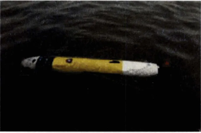
While the large LMRS is still in the development phase, the US Navy already has a man portable UUV in operational use. The REhllUS (Remote Environmental hlonitoring Units) weighs less than 40 kilograms, with a diameter of 19 centimeters and a length of 1.4-2.1 meters. It is powered by Lithium batt,eries with a speed of 3 knots and an endurance of 22 hours (or 8 hours a t 5 knots).[20] It was initially designed for oceanographic measuremerits, but so011 the US Navy deployed it for t,he mine clearance effort of the Umm Qasr port in Iraq, opening the way t,o the British amphibious ship HMS SIR GALAHAD loaded with
humanitarian aids. They also conducted additional UUV operations further up the river at Az Zubayr and Karbala, Iraq. During Operation Iraqi Freedom, the Naval Special Clearance Team-One (NSCT-1) made extensive use of REMUS, exploiting its small size to operate it from rubber combat boats and piers, requiring minimum support.[21] In all, REMUS conducted ten missions in the waters off Umm Qasr, covering a total of 2.5 million square meters. It discovered and marked 97 man-made objects and shapes. In all three locations, a useful by product of this underwater work was the bathymetric data collected and shared with the Port and Maritime Registry, which will help in pending dredging operations. NSCT Ones mission proved that by using UUVs in actual field work in difficult wartime conditions, they were able to achieve a military objective, and also provide valuable environmental and oceanographic data that will be extremely important in the days to come.[8] REMUS
operates down to a lOOm depth, and can be fitted with a variety of advanced sensors including a side scan sonar for MCM tasks.' "The US Navy procured 18 REMUS units, manufactured by Hydroid, and is planning to use them in a number of roles, including environmental survey,
MCM and inspection. REMUS is planned for deployment from small boats, large UUVs and other vessels, including of course mine hunters." [20] The success achieved during Operation
Figure 2.1: UUV Operations in Iraq
Iraqi Freedom also paved the way for export orders. The German Navy Test Center ordered one unit for evaluations in the fields of both MCM and Special Forces. The NATO Undersea
2004, that were initially tested in the Baltic Sea to evaluate their possibilities in traditional mine hunting as well in counter-terrorism in an harbor environment. During these trials REMUS was fitted with some of the latest enhancements (e.g.,
GPS,
dual frequency very high-resolut ion side-scan sonar, acoustic communications between the vehicle and the parent ship). REMUS was also recently ordered by the Royal Netherlands Navy and the Singapore Navy (two units each). [20]2.3
Current UUV Challenges
Commercial and military UUVs share most of the same technology requirements, but as often happens, the military ones are more rigorous. There are different areas of technology involved. Indeed, operating in the undersea realm poses a significant number of complicated engineering issues that must be overcome to adapt current UUV operations to meet the future goals of the US Navy. The major engineering issues can be placed within five sections:
1. Energy: Today's UUVs are battery-powered, and battery capacity remains the most fundamental limitation on range and endurance. Because the power required to propel an underwater vehicle is roughly proportional to its size, and energy capacity to its volume, the mission duration achievable at a given velocity can be shown to vary directly with ship size. Thus, without quantum breakthroughs in energy storage, it is difficult t o imagine small UUVs that are able to perform theater-scale missions or long-dur at ion trailing tasks.
2. Communications: One major aspect of UUV operations rests in their area of opera- t ions; that is, under the ocean surface. Underwater communications remain a difficult task to accomplish, especially when coupled with the size and energy requirements that plague the UUV community. Additionally, the underwater bandwidth capability currently available is quickly exhausted when one considers the large amount of infor- mation that would need to be sent from or to the UUV during information collection missions. Without viable communications, however, the using force would need to
wait until the UUV returns for mission information, which in many cases might be detriment a1 to the mission goals.
3. Navigation: Precision vehicle position sensing is an essential element of control and use of UUVs. It is impossible, for example, t o precisely control a vehicle t o within 1
meter when its position sensor is precise on to 50 meters. Almost all imaginable UUV tasks require the UUV to have a precise knowledge of its own location, whether it be locating underwater mines, or attempting to locate threat vessels; [2 11 not to mention the importance of position knowledge when operating in obstacle rich environments such as littoral regions.
4. Sensors: The underwater realm has led to the development of many technological advanced sensors such as side-looking sonar, electro-magnetic and electro-optic ISR sensors. However, these sensors are both energy hungry and massive in size. The UUV limitation on size and energy require that these sensors, or instruments with similar capability, be re-engineered to be much smaller and in low power configurations.
5. Autonomy: This capability includes the ability to transit long distances, detect, collect information and assess the situation, all of this without human-in-loop inter- vention. It includes key aspects such as mission planning, obstacle and dynamic threat avoidance, and adaptive route planning. The UUV must be able t o collect and evaluate the data, giving different importance to the results, both as a mission product and as it impacts on vehicle operation for the remainder of the sortie. Autonomy is paramount, because in most of the projected missions/scenarios it is very difficult or even utterly impossible to maintain a continuous link with a human supervisor.
Within the framework of these future missions and discernible engineering challenges, this research explores methods in which UUVs can operate in a hostile coastal area, and specifically, demonstrates how decision algorithms can assist UUVs in using coastal specific aspects and terrain to their advantage; more precisely, the benefits of naval choke points and "shipping" lanes. This research will focus on developing methods to allow a relatively
small number of UUVs deploy to detect, acquire, and ultimately engage and destroy a threat vessel. However, to examine the potential benefit of decision algorithms for this system it is crucial to develop a viable test area of operations. This will be explored in the next chapter.
Chapter
3
Area
of
Operations
The purpose of this chapter is to explain the selection methodology for an area of operations to represent a realistic environment in which t o test the algorithms developed in this research and presented formally in subsequent chapters.
3.1 Area
of
Operations
Many future naval combat operations are likely to be in the littorals in order to project combat power ashore and to provide an umbrella of defense for land-based forces. In the littorals, naval operations could be contested with mines, diesel submarines, small coast a1 defense boats, and antiship cruise missiles or long-range artillery. Thus, the military's ability to control and freely operate within these critical areas represents a center of gravity for future military planners. Additionally, operations in these shallow harbor areas present a unique opportunity for military offensive operations. The littoral regions surrounding an enemy nation represent a key transportation node for a nation's military, and UUVs represent a viable tool capable of disrupting an enemy nation's maneuver ability within its own waters. With these concepts in mind, it proved critical to develop a simulation environment that would accurately represent a realistic operating area for UUV operations in future combat operations, and thus serve as a realistic test bed for UUV simulations. Thus, in
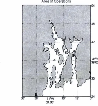
conjunction with past work at Draper Laboratory, Narraganset Bay, Rhode Island was chosen as the representative model. This bay has significant terrain that facilitates complex routing algorithms, and can be easily used t o represent both offensive and defensive scenarios.
Area of Operations
Figure 3.1: Narraganset Bay Area of Operations
More precisely, the area of operations assigned to this simulation is the portion of Nar- raganset harbor that falls North of 41'24'
,
East of -71°36', West of -71'06' and South of 41°54', as shown in Figure 3.1. This area is approximately 2353 square kilometers, of which 579 square kilometers is considered operational water area.Bathymetric data for the area
of operations.
This simulation utilized database information from the National Ocean Service (NOS) hy- drographic data base (NOSHDB), maintained by the National Geophysical Data Center (NGDS) in conjunction with NOS; it comprises the majority of NGDC's area survey hold- ings and provides extensive survey coverage of the coastal waters and Exclusive Economic Zone (EEZ) of the United States and its territories. The NOSHDB contains data digitized
from smooth sheets of hydrographic surveys completed between 1851 and 1965, and from survey data acquired digitally on NOS survey vessels since 1965. The data is presented by providing multiple [LAT,LONG] grids and a corresponding depth presented in meters.
3.1.2
Shipping Lanes
One critical element of autonomous vehicles is their requirement to move safely throughout the real world environment, and account for the various physical obstacles; not to mention the threats that could appear without notice. However, it is also possible for the UUV t o use these same physical obstacles to their operational advantage, and attempt to minimize its own weakness against a stronger enemy force. One pseudo-physical structure that exists in the littoral environment is shipping lanes. When one refers to shipping lanes, the most common structure is the established open-ocean environment where commercial vessels move cargo from port to port; however, shipping lanes also exist within coastal and harbor areas. Harbor regions, specifically, have significant restrictions t o shipping operations. These lanes are more often defined by the depth and width of the waters in the harbor, but can also be shaped by civilian recreation areas, wildlife protection areas, or other political constraints. These established lanes are typically well known and charted on naval charts. Shipping lanes, thus, stand as a good reference t o where ocean going vessels will travel through littoral areas, and provide a natural boundary which UUVs can use to their advantage.
3.1.3
Narraganset Bay Specific Lanes
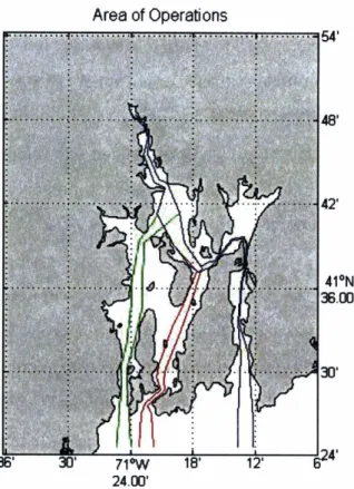
The Narraganset Bay coastal area presents an excellent model for the simulation because of the diverse terrain that lends itself to simulate the shipping lane concept. Although the simulated shipping lane information used for Narraganset Bay was developed t o meet the research needs for this thesis, the routes developed represent a realistic example of any fictional coastal area. Each of the three routes begins a t a modeled northern start point, and transits the harbor region moving from north to south, and ends when the lane reaches open water at the southern exit point of Narraganset Bay.
Area of Operations
For documentation purposes, the routes are labeled according to assumed historical usage (see Figure 3.2), with Route A being the center most route, Route B being the western most route, and Route
C being the eastern route. Table 3.1 provides more detailed information
regarding the specific shipping lanes used in this research.Table 3.1: Narraganset Bay Shipping Lanes
The next step was to transform the chosen operational area and digital bathymetric data into a usable digital framework for use on the simulation.
Route C 41.805" -71.394" 41.411" -71.216" 21 58.85 Km St art Point End Point Total Waypoints Distance
3.2
Digital Map
This digital map methodology takes the grid interval parameter and builds a map that is equal to the dimensions of the operating area, with each square having sides with a length
Route A 41.805" -71.394" 41.411" -71.375" 17 48.73 Km
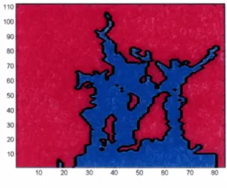
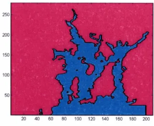
equal to the grid interval parameter. The approximately 300,000 bathymetric data points were then placed into their respective grid squares with the true bathymetric data taken from NGDS services. For simplicity purposes, the script designates each square as either GO or NO-GO terrain. As shown in Figure 3.2, a 1 represents GO water, and the 0 represents NO-GO water.
For the purposes of this research, the minimum depth for UUV operations was determined Route B 41.805" -71.394" 41.411" -71.411" 15 47.24 Km
to be 25 feet of water and thus if one of the bathymetric readings inside each square was equal or deeper than 25 feet, then the entire square was determined to be GO terrain. This metric was chosen to give a realistic combination of stealth and usable operational area.
For comparison purposes only, the following figures show what the digitized map looks like at 1000m, 500m and 200m accuracy levels.
Table 3.2: Example of Discrete Map
Figure 3.3: Digitized Map with lOOOm grid Interval
Figure 3.5: Digitized Map with 200m grid Interval
As Figures 3.3 through 3.5 demonstrate, a larger grid interval size (i.e. 1000 meters) provides a larger operational water area for the UUVs to operate within, but at a cost of accuracy in the fidelity of the true harbor region. The larger gird interval size, however, provides the inherent benefit of a smaller mathematical matrix needed to describe the area in digital format. For example, by using lOOm grid interval the digital map requires 235,200 nodes, while the 1000 meter grid interval describes the same sized terrain with only 9408 discrete nodes. With the desire to combine computational efficiency with a realistic portrayal of the operational area, the decision was made to use 200 meters as the standard grid interval. This grid interval allows for high fidelity modeling of the operational area, see figure 3.5, while allowing future computations to examine only 58,800 nodes.
Chapter
4
Simulation Vehicles
To build a realistic simulation environment in which to test the developed algorithms, it was critical t o simulate both enemy and friendly vehicles accurately. This chapter describes the foundational assumptions used t o design and simulate these vehicles and the mat hematical procedures to simulate the enemy vessels travel through the operational area.
4.1 Enemy
Vehicles
Inherent to the simulation is the creation of a viable enemy force that accurately represents vessels that Allied forces may face in the future. For the purposes of this thesis, three different vessels are designated t o transit through the operational area, and the subsequent peculiarities of each of these ships is modeled in the simulation; these parameters are modeled by changing operating speed, route possibilities, and altering the probability of hit and probability of kill against these specific vessels.
4.1.1
Foundational Assumptions
The underlying assumption in this problem is that threat vessels will be encountered during the course of the simulation and that their ultimate goal is t o transit the bay in a north-south direction and head out to open ocean. One key assumption is that the threat vessels will
remain within the previously established shipping lanes during their transit of the littoral region.
4.1.2
Three Types
of
Simulated Vehicles
In an attempt to accurately represent the broad range of missions the team of UUVs could be tasked t o complete, and thus it is crucial to model several types of enemy vessels. Each of the three simulated vehicles retains specific characteristics that affect the route transited and the speed traveled down the route.
Definitions of key characteristics
1. Max Speed: This is the maximum speed that the ship can hope to attain under normal combat configuration and manning.
2. Cruise Speed: This is the speed that provides the maximum time endurance for the vessel (i.e. they can go this speed for the longest period of time.) This is the speed that one would normally expect to see the vessel traveling at, as it provides the best combination of fuel usage, endurance, and travel time.
3. Draw: This is the depth the ship extends below the surface when loaded to capacity. This aspect of the ship limits its ability to travel through shallow water, and is the primary factor that affects the ships ability t o transit specific waters in and around littoral areas.
4.1.3
Enemy Vehicle
1:
Cargo
Vessel
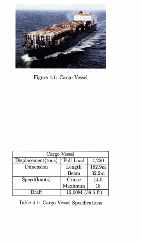
The specifications for the cargo vessel are shown in the Table 4.1, and are representative of a general cargo vessel. Modern armies deploy their combat forces via these typical commercial vessels, they re-supply their deployed forces on these ships, and/or their economy is founded on their ability t o import/export key resources. Thus this ship is representative of a possible target for a naval commander charged with denying enemy usage of littoral areas, or as part of an on-going campaign to at
. , & : 5 j . - J + f
Figure 43: C&go Vessel
Table 4.1: Cargo Vessel Specifications Cargo Vessel Displacement (tons) Dimension Speed(knots) Draft Full Load Length Beam Cruise Maximum 4,250 182.9m 32.2m 14.5 18 12.00M (39.5 ft)
Enemy Vehicle
2:
Ocean Surveillance Vessel
Figure 4.2: Ocean Surveillance Vessel
.
3>;,d*
,.
* COcean Surveilla+.yce Vessel
Displacement (tons) Full Load 2,30 1 Dimension Length 68.3m Beam 13.lm Speed(knots) Cruise 10.5 Maximum 15 I I Draft 4.6M(15ft)
Table 4.2: Ocean Surveillance Vessel Specifications
The ocean surveillance vessel is designed to represent a typical medium-sized vessel that
could be used by enemy forces for a variety of tasks. Ships of this size are often used as
part of larger naval task forces to conduct mine warfare, electronic reconnaissance or anti- submarine tasks. Possible engagements against this type of ship are most likely during the naval preparation of a harbor area for follow-on action, or clearing the area for a special forces insertions. The specifics of this type of ship are shown in Table 4.2.
Enemy Vehicle
3:
Frigate
The frigate represents a typical enemy ship of war. It has the capability to move both in open ocean and shallow coastal areas. It is typically armed with extensive weapons that protect it from both air, sea and sub-surface threat vessels. Engagements against a ship of this type are most likely in an effort to destroy dangerous enemy ships before they are able
Figure 4.3: Typical Naval Frigate
Frigate Vessel
-
I
Displacement(tons~1
Full Load1
3.8501
I
DimensionI
Length1
126.5m1
Speed (knots) Cruise Maximum
4.2M(15.6ft) Table 4.3: Frigate Vessel Specifications
to move into open ocean and hinder friendly vessels freedom of maneuver outside the direct area of operations. The specifics of this type of ship are shown in Table 4.3.
Enemy Movement Assumptions
With three types of enemy ships designated within the simulation environment, the next step is to develop a method to present the enemy movement through the operational area. Using
the foundational shipping lanes presented in Chapter 3, the simulation uses a randomized metric to portray realistic enemy movement against which the system of friendly UUVs will operate.
4.2.1
Route
One critical assumption of this thesis is the foundational use of shipping lanes for water transit of the threat vessels. In this simulated environment, three enemy vessels are starting at the northern starting locations. Each enemy vessel is attempting to move from its harbor start area into open waters to complete an unspecified mission. Each of the three vessels will transit through the battlespace. However, based on harbor characteristics, not every route is viable for each vessel. This is reflected by the following table:
Table 4.4: Ship Lane Usage Ship 1
Ship 2
Ship 3
In a harbor region, historical information can either be inferred or is actually tracked by authorities. The historical route usage in Narragansett Bay is assumed to be the following:
Lane
A
GO GO GO
Lane
A
LaneB
LaneC
C
I
Table 4.5: Historical Lane Usage Proportion Lane
B
NO-GO GO GO
Using these proportions, a random number generator selects the threat vessel type of ship Lane
C
NO-GO NO-GO NO-GO
(with equal probability for each of the three ships), and using the lane usage proportion, a specific route is assigned for the enemy vessel to transit. The following table shows the specific route probabilities for each of the three ships:
I
I
LaneA
I
LaneB
I
LaneC
I
4.2.2
Waypoints
For each enemy ship its specific route of travel, the natural tendency is to remain in the center of the shipping lane to reduce the opportunity for incident. To model this, a normal curve was placed around the center of each waypoint on the selected route, with a standard deviation of 25% of the width of the lane at that specific waypoint. For each subsequent waypoint selection, a random number generator derived a projected waypoint for each of the pre-established turn points along the selected routes. The projected route then draws a straight line from the current turn point to the next turn point. It is assumed that the threat vessel will not turn except at these established waypoints.
4.2.3
Speed
Each of the three enemy vessels will travel at different speeds, based on the route they travel, and the characteristics of the vessel. From a tactical perspective, one would not expect the enemy vessel to travel at maximum speed in the harbor; this would waste valuable fuel, and make the route especially hazardous due to restricted terrain.
1. Initial Speed: At the beginning of the simulation, the enemy vessel is assigned a speed value that is drawn from a normal distribution of the specified cruise speed, with a standard deviation of 25% of the average speed.
Table 4.7: Initial Speed Distribution Ship 1
Ship 2
Ship 3
Additionally, of note, is that since the enemy vessel is starting its travel at the initial location, the time must reflect the need to accelerate t o the required initial speed. Clearly, complicated models could be developed to measure and calculate the acceler- ation of each of the three types of enemy vessels. However, for simplicity, it is assumed
Initial Speed (knots) 14.5 10.5 20 Standard Deviation 3.625 2.625 5
that the enemy vessel will reach its desired speed after 5 minutes with a constant acceleration from zero knots t o the selected initial en route speed.
En-route speed changes: It is obviously possible that the enemy vessel can make speed changes at any time along the route. For this simulation, it is assumed that the vessel will not make speed changes except at turn points. That is, between turn points the enemy ship's velocity is constant. At turn points, the vessel will be assigned a new speed that is again based on a normal distribution around the current en-route speed with a standard deviation shown in the above table. At no point is the threat vessel allowed to move at a velocity that is below five knots or greater than the maximum speed for the type of ship being simulated. Five knots was chosen as the minimum speed as an estimate of the minimum value that any ship would choose to travel through the operational area.
4.2.4
Calculate the Exact Enemy Route
At this point in the simulation, the enemy ship has a set number of waypoints t o comprise its actual path through the operational area, and a random number generator, using the above methodology, has assigned a speed for each of the legs of travel. The final step for use in this simulation is to take the waypoints and speeds and assign a
[LAT,LONG]
grid for every 1 minute of travel, beginning at the northern start point and ending at the pre-defined end point of the chosen shipping lane. It is important to note that during this process there was no interaction with the physical or digital map during these calculations. Each of the shipping lanes was designated as viable water space throughout the route. Because the structure of the enemy path is designed around the shipping lanes, it is guaranteed that the enemy vessel will not travel outside of viable water. Figure 4.4 shows a sample of multiple independent enemy movements through the simulation environment.Figure 4.4: Enemy Travel through Shipping Lanes
Friendly Mission Statement
For the purposes of this research, a notional mission statement was developed to explore the
possibilities of using UUVs in the offensive role. Although much literature focuses on the ASW mission for the UUV, it is also viable that the UUVs could be used to engage larger surface vessels during the course of armed conflict or other naval engagement. Thus, it can be seen as a viable task for a naval commander to destroy ships in littoral regions to meet a desired end state in a complex geo-political framework. These effects could be destruction of
specific ships to prevent the personnel or cargo on board from reaching their ultimate goal, .or the destruction of any ship to affect the morale of the enemy forces, or simply engage
targets to act as a distractor to enemy forces.
The friendly units are tasked with intercepting a possible known enemy vessel that has left the northern start point, and is heading for open water to an unknown location. The friendly vessels must acquire the threat vessel, and subsequently report acquisition to higher
headquarters. Only after higher headquarters has analyzed the situation report and the UUVs have received permission to engage can the team of UUVs engage the vessel with
intent to damage or destroy. To accomplish this task, three teams of two UUVs each will be deployed into the target area. The first two teams will be comprised of "hunter" UUVs
which will be tasked with the initial acquisition and reporting of threat information. The final team will be tasked with the actual interception and engagement of the threat vessel.
4.4
Friendly Vehicles
In the course of developing a viable simulation to evaluate the decision algorithms, it is essential t o develop representative vehicles that can capture a combinat ion of current or realistic future capabilities of UUV technology. The technological gap between current and possible future capabilities is indeed unknown, and thus it is not trivial t o determine a
viable representation of vehicles to examine the offensive role. As quickly as tactics and methodologies are developed, new technologies can mandate a change to operational schemes; the tactics and methodologies that UUVs use must be a reflection on their capabilities. For example, a UUV that has sensor capabilities of 2000 meters would tactically respond and react to enemy movement different then that of a UUV with a sensor range of only 750 meters. Although the future capabilities of UUVs will surely demonstrate enhancements from current operational vehicles, it is imperative to demonstrate some reasonable expectation of performance. Given the broad range of mission objectives that UUVs might be called upon to explore, it is a common belief that UUVs will evolve into "four distinct classes of
UUVs.
The four classes of UUVs would be defined by their size: large diameter vehicles of greater than 21 inches; vehicles of 21 inches (similar to the MK48 torpedo); vehicles of 12-314 inches (similar to the lightweight torpedo); and smaller UUVs." [1] Therefore for this research, two separate UUV's, each with distinct capabilities, are modeled; a killer UUV armed with torpedoes and a hunter UUV armed with advanced sensor arrays.4.4.1
Foundational Assumptions
For the purposes of this simulation, assumptions must be established regarding friendly UUV capabilities; although current technology does not meet all described technical capabilities in this thesis it is believed that they represent a fair approx~mation of where technology could
be in the near future.
1. Endurance: One common difficulty in developing autonomous UUVs is the endurance of the platform. For the purposes of this research, it is assumed that each of the UUV7s possesses the required endurance to move to position and complete one iteration of the mission profile and return to a safe loca,tion for maintenance and/or refit. While it is indeed likely that after one mission execution, or in the middle of a mission cycle, a UUV would exhaust its endurance, we can assume that a hand-off of mission requirements can occur seamlessly with another single or team of UUVs that provide relief on station.
2. Communications: Underwater communications, both near and far, have been a con- stant challenge for both manned and unmanned vessels. For this research, it is assumed that all operational UUV's have a method to communicate with home base when they are stationary; possibly through some floating low-observable antenna. It is also as- sumed that the UUVs are out of contact when they are mobile.
3. Sensor Range: The technology of sensors is ever advancing, and their are a variety of sensors available to accomplish the myriad of mission specific tasks. For this simulation, the assumption is that the UUVs are equipped with sonar type sensors that have a specified range. This range allows the UUV to have 360" acoustic visibility out t o the range for each system. That is, they can "hear" any activity within their sensor range, and subsequently determine, from their location, the bearing at which the acoustic activity occurred.
4. Weapons Systems: Although there is no current open-source information regarding armed UUVs, it is logical to assume that in the future such configurations are possible. Additionally, there is a certain level of ambiguity when discussing types of weapons sys- tems that could be employed against threat vessels, and whether or not these weapons systems could provide an adequate size to lethality ratio that make them practicable
for UUV ~perat~ions. Despite t,he engineering challenges, for this research the assump- tion is that, it is possible t,o a,rm UUVs with multiple individual weapons with a discrete weapons range. These weapons can be fired from a distance wit,hin their designated range, and once all available weapons have been fired, t,he UUV is no longer lethal. Within the contaext of t, hese assumpt ions, two discrete friendly UUVs were denoted to accomplish the critical t,asks. The Hunter UUV a i ~ : l the Killer UUV were assigned specific tasks and these are presented as follows.
4.4.2 Hunter UUV Mission Specifications
The first UUV, the detector, will have the operationa,l task of clandestine movement int,o the prescribed area of operations, and subsequent long-term monitoring of its assigned area of operations. It is assumed that t,his UUV is smaller in size to allow t,his clandestine movement, and its size is optimized for long endurance: a,s movement into the operational area can be a slow delibera,te movement. This UUV will be armed with only sensors and comm~lnications equipment allowing it t!o acquire threat vessels, and subsequently pass this information to a higher headquart,ers for further guidance.
4.4.3 Killer UUV Mission Specifications
The second UUV, the killer, will have the operational task of on-order moving to the en- gagement area, locating the enemy vessel, and engaging the enemy vessel in order to ma,ke itJ combat ineffective or to dest,roy it. This UUV would be much larger than the first, aforemen- t,ioned clandestine UUV, due t o t,he ammunition requirements. Additionally, it is assunled that this larger UUV sacrifices long endurance for greater speed; that, is, once an engage- ment occurs it must return to friendly forces for maintenance and/or energy replenishment. Thus UUV will be armed with a varyirlg amount of lethal t.orpedoes and requisite sensor capabilities to acquire the t,hreat and process the subsequent engagement.