Design and Control of a Spheroidal Underwater Robot for the Inspection of
Nuclear Piping Systems
by
Martin Lozano, Jr.
Submitted to the
Department of Mechanical Engineering
in Partial Fulfillment of the Requirements for the Degree of
Bachelor of Science in Mechanical Engineeringat the
Massachusetts Institute of Technology
June 2012
ARCHIVES
OF TECHNOLOGY
JUN
28
2012
LIBRARIES
I
@ 2012 Massachusetts Institute of Technology. All rights reserved.
Signature of Author:
K
-;r Z
Certified by:
Department of Mechanical Engineering May 11, 2012
H. Harry Asada
Ford Professor of Mechanical Engineering Thesis SupervisorAccepted by:
(
John H. Lienhard V
Samuel C. Collins Professor of Mechanical Engineering
.01
1/
Design and Control of a Spheroidal Underwater Robot for the Inspection of
Nuclear Piping Systems
by
Martin Lozano, Jr.
Submitted to the Department of Mechanical Engineering on May 11, 2012, in Partial Fulfillment of the
Requirements for the Degree of
Bachelor of Science in Mechanical Engineering
ABSTRACT
While it is critical that nuclear plants frequently inspect their facilities for cracking, corrosion or other failure modes, humans cannot safely perform these tasks due to the hazardous conditions within the tanks and piping systems. In response, the d'Arbeloff Laboratory in the Mechanical Engineering department is designing a compact submersible robot that is capable of precise navigation and maneuvering in order to detect defects within water filled piping systems. The robot is spheroidal with a smooth surface and no external appendages. It propels itself with centrifugal pumps which suck in water from the environment, and pump it out in various directions.
This thesis covers the design and implementation of the software, electrical, and a few mechanical systems of the robot. Specifically, it details the programming techniques for the microcontroller and graphical user interface code, circuit board design, wiring, and
waterproofing. A robot prototype was built, and experiments have given useful data to construct a model to supplement the field of underwater robotic design.
Thesis Supervisor: H. Harry Asada
Acknowledgments
I would like to thank Professor Asada whose class, 2.12 - Intro to Robotics, served as the foundation of my robotics education. He later accepted me as a UROP stu-dent and allowed me to work on a project that I found interesting, educational, and relevant.
I also owe a huge debt of gratitude to Anirban Mazumdar, a great UROP super-visor, friend, and mentor. Without his support and guidance, my thesis would not have been as enjoyable or productive of an experience. This project also could not
have been completed without the help of Meagan Roth and Aaron Fittery.
Finally a large thank you goes to my family and friends, whose tremendous support these past four years has been a large part of my success.
Contents
1 Introduction 15
1.1 Motivation ... ... 15
1.2 Robot Description . . . . 16
1.3 Pump Valve Architecture . . . . 18
1.4 Outline of Paper . . . . 19
2 Electronic Hardware 21 2.1 M icrocontroller . . . . 21
2.2 Radio Transceiver . . . . 22
2.3 M otor Driver . . . . 22
2.3.1 TB6612FNG Dual Motor Driver Carrier . . . . 23
2.3.2 Qik 2s9v1 Dual Motor Controller . . . . 24
2.4 Gyroscope . . . . 24
2.5 Pum p . . . . 25
2.6 DC Motor ... ... 26
2.7 Battery . . . . 26
2.8 Circuit Design . . . . 27
3 Incorporation of Electronics into the Robot 31 3.1 Electronics Housing and Wiring . . . . 31
3.2 W aterproofing . . . . 31
4.1 Introduction . . . . 35 4.2 Previous Work . . . . 35 4.3 Program Initialization . . . . 36 4.4 Radio Communication . . . . 37 4.4.1 Previous Work . . . . 37 4.4.2 Modifications . . . . 39 4.5 Command Directory . . . . 40 4.6 Noteworthy Features . . . . 41 4.6.1 Flapper Behavior . . . . 41 4.6.2 Gyro Behavior . . . . 41 4.6.3 Safety Features . . . . 41
5 High Level Software Control 43 5.1 Introduction . . . . 43
5.2 Graphical User Interface . . . . 43
5.2.1 Communication with Arduino . . . . 44
5.2.2 Switchable Drive Plane . . . . 44
5.2.3 Flapper Control . . . . 46 5.2.4 Pump Control . . . . 46 5.2.5 Safety Features . . . . 46 5.3 Gyroscope . . . . 47 5.3.1 Single Query . . . . 47 5.3.2 Continuous Measuring . . . . 47 6 Results 49 6.1 Introduction . . . . 49 6.2 Robot Operation . . . . 49 6.3 Position Control. . . . . 50 7 Conclusion 55 7.1 Overview. . . . .. . . . . 55
7.2 Future W ork . . . . 56
7.2.1 Cam era System . . . . 56
7.2.2 Com munication . . . . 56
List of Figures
1-1 Photographs of the prototype robot. . . . . 17 1-2 A schematic diagram (left) and a CFD image of the CJD design (right). 18 1-3 A schematic diagram of pump-valve architecture (left) and a photo of
the physical prototype (right). . . . . 19 2-1 Onboard microcontroller used in our robot design. Its small size and
large feature set made it an ideal choice for our application. . . . . . 22 2-2 High-sensitivity radio transceiver used to wirelessly communicate with
the robot. . . . . 23 2-3 Dual motor driver used to control the robot's two drive pumps. . . . 23 2-4 Dual motor driver used to control the flappers on the CJDs. . . . . . 24 2-5 Two-axis gyro that measures rotation rates in the pitch and yaw axes. 25 2-6 The two centrifugal pumps used to suck in water for the valve system. 26 2-7 The onboard battery that powers the robot. . . . . 27 2-8 A schematic of the electronics within the robot. . . . . 28 2-9 The circuit board layout for the electronics. . . . . 28 2-10 The populated circuit board for the robot prototype. Note the layered
design to minimize size. . . . . 29 2-11 The populated circuit board for a propeller-actuated robot prototype.
This board has an additional Qik motor driver. . . . . 29 3-1 A CAD model of the robot design. Note the streamlined shape and
lack of appendages. . . . . 32 3-2 A CAD model of the space reserved for electronics. . . . . 32
3-3 Models for the electronics-half of the robot. The central box is fabri-cated from waterproof material, snaps together with the two sides, and prevents free motion of the electronics. . . . . 34
4-1 A conversion table from ASCII characters to other values. . . . . 38 5-1 User input from this GUI (created in Matlab) remotely controls the
underwater robot. . . . . 45
6-1 The results of one of the robot's drive control tests in which it was commanded to drive backwards, then immediately forwards. The soft-ware tracked the center of the robot (top), and then plotted the robot's calculated velocity with respect to time (bottom). . . . . 51 6-2 Experimental results of the closed-loop PWM controller when
com-manded to drive forward at a desired yaw angle. The controller stabi-lizes the robot at the desired angle, while the unstable open-loop (no controller) immediately misses the desired value with increasing error. 52 6-3 Results of a disturbance rejection test. The robot was commanded to
drive forward with no yaw angle, then spun. The data from the gyro allows the controller to correct the error and return to its original angle. 53
List of Tables
4.1 Pin assignments on the Arduino. 'A' denotes an analog pin; all others are digital. "'' denotes PWM output capability. . . . . 36 4.2 Directory of input commands for the Arduino code. . . . . 40
Chapter 1
Introduction
1.1
Motivation
As nuclear powerplants age, their components degrade and require frequent inspection and maintenance. Corrosion at metal joints and pipe leakage are examples of the safety challenges that exist today. Typical inspections involve shutting down the reactor and then inspecting critical areas. The desire to make these inspections more efficient has created a growing interest in robotic inspection techniques. Several research projects on external pipe inspection, such as those by Mackenzie [1], and Buckingham [2], have been reported.
Despite these advancements there is an increasing need for direct inspection of possible corrosion sites and cracks from inside the pipes and reactor itself. Robots that can carry cameras and other sensors directly to the inspection site can provide additional valuable information. To this end several snake-like robots from both industry and academia have been developed for deployment inside the water filled piping systems of nuclear reactors [3].
An alternative approach is to use small underwater Remotely Operated Vehi-cles (ROV) inside the water-filled pipes that can travel deep into the piping systems and around corners. Several companies have developed similar underwater vehicles, however the presence of cables remains a key challenge. Cables are used for commu-nication and power transmission, but long cables can interfere with the dynamics and
control of small underwater vehicles. The author's research group envisions that the use of tetherless compact ROVs with a high level of maneuverability has the potential to further improve the direct inspection capability of nuclear power plants.
1.2
Robot Description
Robots intended for use within the nuclear reactor environments are subjected to very strict requirements. We will focus on three key functional requirements outlined below as a valuable starting point for the research and development of prototype direct inspection robots.
1. Untethered: Tethered underwater robots have been developed for nuclear power plant inspection. Use of a tether resolves many technical challenges that an untethered vehicle design has to overcome, and will be a practical solution to many inspection problems. However, tethers limit accessibility of the vehicle, as cables may get tan-gled with various appendages and obstacles. Furthermore, a long tether limits the maneuverability and control fidelity of the vehicle. Finally, maintenance and storage of long cables is costly and troublesome.
2. Compact, tangle-free body shape: For accessing a confined area the vehicle must be compact. To this end, components must be internal, electronics must be miniaturized, and battery size must be minimized. Batteries tend to comprise a large fraction of the total mass and volume, so making the vehicle efficient through de-sign and controls is essential. Furthermore, to avoid interference with the existing structure and minimize the chance of getting stuck, the body of the vehicle must be smooth and have minimal appendages. Streamlined shapes without external pro-pellers or rudders are therefore a desirable approach.
3. Precision low-speed maneuvering: The vehicle must be able to deliver sensors and cameras precisely to a specified inspection site. Precise multi-axis positioning and maneuvering are required for the exploration and inspection of confined spaces and complex environments such as piping systems. Additionally, in order to carry out sophisticated visual inspection, high-precision control is necessary. Moreover,
due to low video frame rates, these inspections must be performed at low enough speeds for the operator to sufficiently evaluate the images and conditions. Low-speed maneuvering presents unique challenges since control surfaces such as fins and rudders scale with the square of velocity. Also, at very low speeds propeller thrusters may be commanded to only rotate a few times. This can cause them to act in a manner that is difficult to control ([4], [5]).
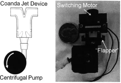
Our new robot design concept addresses all three of these important requirements; the vehicle is designed to be tetherless, compact and streamlined, and capable of precision low-speed maneuvering (Fig. 1-1). The robot is spheroidal with a completely smooth outer shape and has 5 degrees of freedom. This is achieved by using central centrifugal pumps that draw in fluid and then expel it at high velocity from various exit ports depending on the desired direction. High speed valves are used to switch the direction of the jets. Previous work by our group has outlined the fluidic valves which we refer to as Coanda Jet Devices (CJD) [6], and provided preliminary analysis on how they can be used for the maneuvering of underwater vehicles. This paper will next review the Coanda Jet Device and outline the relevant models used for analysis.
1.3
Pump Valve Architecture
The Coanda Jet Device is a fluidic valve based on the Coanda effect. As Figure 1-2 illustrates, a flow enters the device at the inlet I, and the control ports C1 and C2 are used to control the exit flow. If control port C1 is closed while C2 is opened to ambient pressure, the jet will exit E1. If control port C2 is closed and C1 is opened the flow
will exit E2. This phenomenon is based on the Coanda Effect [7], and allows high
speed switching of jets with very simple and compact hardware. A Computational Fluid Dynamics (CFD) image is also provided in Figure 1-2. Note how the jet bends completely and exits only from the right side exit. For further details on the device design and underlying physics, see [6], [8].
Exit E1 E
Control Port Control Portr
C1 - C2
Inlet I
Figure 1-2: A schematic diagram (left) and a CFD image of the CJD design (right).
One use of the CJD is to apply the device directly to a centrifugal pump and therefore allow the centrifugal pump to provide a jet in two directions (Fig. 1-3). Centrifugal pumps hold several advantages: they are mechanically simple, commer-cially available at a range of size scales, and they are driven by DC motors and can be combined with simple and compact drive electronics. The key innovation is that this combination will be lighter than simply combining centrifugal pumps together. The bearings, seals, motor and gearbox that comprise most pumps can be substantially
heavier than a simple plastic CJD and its associated switching mechanism.
Coanda Jet Device
Centrifugal Pump
Figure 1-3: A schematic diagram of pump-valve architecture (left) and a photo of the physical prototype (right).
1.4
Outline of Paper
This paper begins with an overview of the electronic hardware needed in the de-sign, detailing each component used in the robot, as well as the printed circuit board (PCB). Chapter 3 discusses the incorporation of the electronics within the actual robot, including waterproof housing. Chapter 4 describes the low level software con-trol programmed on the robot's microconcon-troller. Chapter 5 explains the high level software such as the graphical user interface (GUI) and data processing. Chapter 6 shows the implementation of the electrical and software systems within a robot prototype. Finally Chapter 7 discusses the conclusions and details for future work.
Chapter 2
Electronic Hardware
2.1
Microcontroller
A microcontroller is a small computer on an integrated circuit, often containing a processor core, memory, and programmable inputs and outputs. They are used in automatically controlled products and devices, such as automobile engine control systems, implantable medical devices, and other embedded systems. Due to their relatively small size and cost, microcontrollers make it economical to digitally control devices and processes. Our design uses an onboard mixed signal microcontroller capable of integrating analog components needed to control non-digital electronic systems. It handles the low level logic, activating each component when necessary, creates and deciphers the radio signals sent and received, coordinates pump and actuator behavior, and handles the information from the onboard gyro.
Specifically our robot is equipped with an Arduino Pro Mini 328 (Fig. 2-1). This microcontroller is thin (0.8mm) and has a small footprint (0.7x1.3 inches). Designed by SparkFun, it is a 5V Arduino running the 16MHz bootloader. It features USB connection off board, a reset button, 5V regulator, over current protection, reverse polarity protection, DC input up to 12V, and on board Power and Status LEDs [9].
It also offers 4 analog and 13 digital pins which is enough to interface with all the other components.
Figure 2-1: Onboard microcontroller used in our robot design. Its small size and large feature set made it an ideal choice for our application.
2.2
Radio Transceiver
A radio transceiver is a single unit which contains both a receiver and a transmitter, capable of sending and receiving radio signals for communication. It allows our design to be tetherless, sending commands to the robot and receiving data (such as position or camera data) without the use of wires. Our robot uses an easyRadio Advanced 433-4MHz multi-frequency transceiver (Fig 2-2). easyRadio Advanced modules include the ability to change bandwidth of the radio from 19.2KHz down to 12.5KHz, which means narrow-band performance on a wide-band budget. They also feature temporary channel/power level selection, allowing the user to scan other channels without storing the settings in internal memory, free flash firmware upgrades that can be quickly programmed to make a future proof solution, and temperature compensation for frequency accuracy less than +/- 1KHz over full temperature range [10].
2.3
Motor Driver
The motor driver governs the performance of the motor in some predetermined man-ner. It might include a manual or automatic means for starting and stopping the motor, selecting forward or reverse rotation, selecting and regulating the speed, regu-lating or limiting the torque, and protecting against overloads and faults. Our robot uses two different motor controllers.
I I IlliflI
Figure 2-2: High-sensitivity radio transceiver used to wirelessly communicate with the robot.
2.3.1
TB6612FNG Dual Motor Driver Carrier
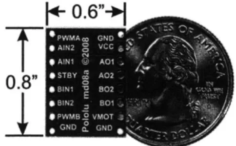
The TB6612FNG (Fig. 2-3) is a dual motor driver for interfacing two small DC motors to a microcontroller (Arduino). It uses MOSFET-based H-bridges as opposed to BJT-based H-bridges commonly used in older drivers. MOSFET-based H-bridges are more efficient, allowing more current to be delivered to the motors and less to be drawn from the logic supply. The small breakout board gives direct access to all of the features of the TB6612FNG chip and adds power supply capacitors and reverse battery protection on the motor supply. Each of the two motor channels has two direction control pins and a speed control pin that accepts a PWM input with a frequency of up to 100 kHz [11]. This motor driver is used to control the two drive pumps that circulate fluid throughout the robot.
+
0.6"+
n
2.3.2
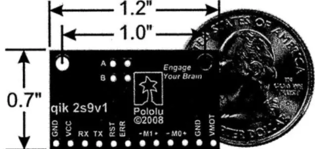
Qik 2s9v1 Dual Motor Controller
The Qik 2s9v1 (Qik) (Fig. 2-4) is a second-generation dual serial motor controller. The compact board allows the microcontroller to drive two small, brushed DC motors with full direction and speed control. Improvements over the previous generation in-clude high-frequency PWM to eliminate switching-induced motor shaft hum or whine, a robust, high-speed communication protocol with user-configurable error condition response, and reverse power protection on the motor supply [12]. It also features two on-board indicator LEDs (status/heartbeat and serial error indicator) for debugging and feedback. Two of these motor drivers are used to control the four flapper-motors on the CJDs.
1.2"
1.0"
0.7"
eqi 2sv e ee ae eeFigure 2-4: Dual motor driver used to control the flappers on the CJDs.
2.4
Gyroscope
A gyroscope (gyro) is an electronic, microchip-packaged MEMS (micro-electro-mechanical
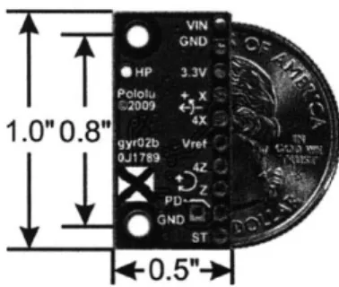
systems) device for measuring or maintaining orientation, based on the principles of angular momentum. When the gyro is turned at a steady rate about its input axis, a torque is applied to the spin axis. This causes the gyroscope to precess about the output axis through a damping fluid that resists motion. The rate of precession is di-rectly proportional to the rate of turn of the gyroscope about its input axis. Through integration, the total angle of movement about the output axis will be proportional to the speed and length of time the input axis is turning.
the pitch and yaw axes of the robot. Specifically we are using a a basic breakout board for the ST LPY510AL dual-axis gyro (Fig. 2-5). Two separate analog voltage outputs for each axis provide angular velocity ranges of 100 deg/s and 400 deg/s. This board has a 3.3V regulator for easy integration with the 5V components we are using, includes a low-pass filter on each output for noise reduction, and has an overall size of half a square inch [13]. Data taken from this gyro is transmitted from the robot to the operator's computer for position and speed analysis.
Figure 2-5: Two-axis gyro that measures rotation rates in the pitch and yaw axes.
2.5
Pump
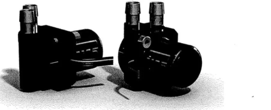
Centrifugal pumps were chosen as the basic propulsive component due to their me-chanical simplicity, availability at small size scales, and the ease of use with electronic circuitry. However, one common issue with some centrifugal pumps is that they are not reversible. This means that the pump can only provide force in one direction and will need to be combined with a second one in order to achieve bi-directional forces. With a reversible pump, the exit ports can be designed to provide forces in two di-rections. Our group has developed a retro-fitted pump design to achieve this while eliminating backflow (fluid loss through the unused exit port). Specifically our design uses two waterproof TCS M400S micro centrifugal pumps running on 12V (Fig. 2-6).
Figure 2-6: The two centrifugal pumps used to suck in water for the valve system.
2.6
DC Motor
Four small DC motors are used as the switching mechanism for the CJDs. Waterproof TCS M200S micro centrifugal pumps were chosen due to their small size. The top housing and impellers were removed and replaced with a custom flapper attachment to open and close the control ports. The right image in Figure 1-3 shows a valve prototype.
2.7
Battery
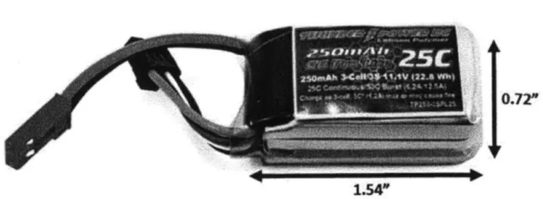
As mentioned in the Introduction, batteries often comprise a large portion of a robot's mass and volume. Our design uses lithium polymer batteries (LiPo) because of their high power density and small weight. They are also generally cheaper than lithium ion batteries and come in a wide variety of shapes. LiPo batteries are packaged in pouch cells. Unlike lithium-ion cylindrical cells, which have a rigid, heavy metal case, pouch cells have a flexible, light, foil-type case. Our current robot uses a Thunder Power RC G6 Pro Lite 25C Series LiPo Battery capable of 250mAh at 11.1 volts (Fig. 2-7).
1.54"
Figure 2-7: The onboard battery that powers the robot.
2.8
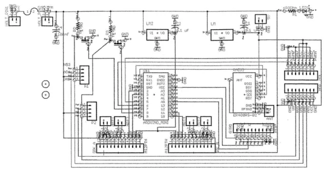
Circuit Design
With all of the components chosen, an electronic schematic was designed to appropri-ately wire the circuit as a whole (Fig. 2-8). This was done in CadSoft's Eagle software program for easy manipulation, editing and error checking. A fuse was added to the schematic to prevent short circuits from damaging the electronics. Similarly, other basic electronic components were placed in the circuit: capacitors to reduce electrical noise, voltage regulators to control the voltage supplied to components, mosfets for electrical switching (used to change the direction on the pumps), and headers to plug in the motors and pumps.
After all the components were laid out, a circuit board was designed, again within Eagle. Use of a PCB greatly reduced the amount of wires needed to connect electrical components, decreasing the overall mass and size, and avoiding tangles. Components were packed and configured to minimize the board's overall footprint. To this end, a multi-layered architecture was used to allow certain chips to overlap other chips or small components. The board's final dimensions were 1.9x1.65 inches (Fig. 2-9). The board's data files were sent to a fabrication house, and, after delivery, it was populated (Fig. 2-10). Note the layered architecture; several areas of the board have three tiers.
A second board (Fig. 2-11) featuring an extra motor driver (another Qik) was designed and created for a later robot design that uses a propeller for forward actu-ation.
Figure 2-8: A schematic of the electronics within the robot.
+-+-+--+-+-
*
I165"
Figure 2-10: The populated circuit board for the robot prototype. Note the layered design to minimize size.
Figure 2-11: The populated circuit board for a propeller-actuated robot prototype. This board has an additional Qik motor driver.
Chapter 3
Incorporation of Electronics into
the Robot
3.1
Electronics Housing and Wiring
With the electronics assembled onto a single, compact PCB, we next considered incorporating it into the overall robotic design. Other members in our group had already developed the shape, size, and configuration of the valve architecture (Fig. 3-1), reserving a large space (nearly half of the entire design) for electronics and wires (Fig. 3-2). To determine the exact amount of space needed, CAD models of the electronics were designed in Solidworks and manipulated within the structure. It was determined that only the center 2.25 inches were necessary. A box-like structure was designed to adequately constrain the electronics (extra space would allow them to slide around, altering the robot's center of gravity during operation). The top of the box was designed to interface with a previously purchased water-tight lid.
3.2
Waterproofing
One of the most important aspects of the design was the waterproofing of the elec-tronics. Several methods were considered, such as conformal coating and potting, but these encase the electronics and prevent further alteration. Our group wanted the
Figure 3-1: A CAD model of the robot design. Note the streamlined shape and lack of appendages.
freedom of removing or replacing components within the circuit (for example remov-ing the Arduino to program it, unpluggremov-ing the pumps or certain motors, rechargremov-ing the battery, etc.). We decided to create a waterproof box-like structure with a re-movable top (Fig. 3-3, center). We had used commercially bought watertight boxes for previous prototypes and test beds due to their availability and low cost. For the final robot prototype, we designed a custom box that would minimize unused space and conform to the robot's contours. The top of the box matched the commercially bought boxes, allowing us to use the original gasket-lined tops.
Four pegs were placed on the sides of the box to snap together with the two outer sides (Fig. 3-3), making up the top half of the robot. Small slots were also placed on the sides of the box to thread the wires for the pumps and motors. This housing was printed on a high resolution stereolithography 3D printer out of a waterproof composite. After fabrication the wires were fed through, and the slots were sealed with epoxy.
Figure 3-3: Models for the electronics-half of the robot. The central box is fabricated from waterproof material, snaps together with the two sides, and prevents free motion of the electronics.
Chapter 4
Low Level Software Control
4.1
Introduction
The Arduino microcontroller uses the Arduino programming language and the Ar-duino development environment. A great benefit of programming in ArAr-duino is the open-source support and resources available online. Arduino has a large online com-munity of hobbyists, artists, and designers who often upload their work, code, and designs. Furthermore, several hardware manufacturers, and general users, offer li-braries (files of code written in C or C++ which provide extra functionality, such as the ability to control an LED matrix, or read an encoder, etc. [14]) for use with their hardware. Our code uses a library to improve the Arduino's control of the Qik motor drivers. Additionally, to save programming time, the code was written to be used with both robot designs (with and without propellers). For this reason it communicates with three Qiks and can control two, optional propellers.
4.2
Previous Work
One of our group's members, Megan Roth, previously wrote a control code for a sim-pler robot prototype. It read single-character inputs into the Arduino environment's serial command window to toggle a light, swim straight or turn at a constant rate, or stop. I built upon her work, keeping much of her setup code, as well as her use of
characters to trigger certain actions.
4.3
Program Initialization
Each time an Arduino program first runs, all pins to be used, whether digital or analog, must be declared as inputs or outputs. Our code, specifically, also needs to establish communication with the three Qiks upon startup. This requires assigning three digital pins on the Arduino for each Qik (one to transmit, one to receive, and one to reset the signal), using nine of the 13 digital pins available. However after the initial setup, the Qiks no longer need to be reset, creating three unused pins. To utilize these pins, the code first establishes communication with the Qiks, then reassigns the reset-pins to be used with other components. Using this priority-based juggling of pins, our single Arduino board can interface with a greater number of sensors and actuators. Table 4.1 shows the pin assignments of the Arduino. Pin numbers preceded with an 'A' are analog pins; all others are digital. The starred pins are capable of outputting a pulse-width modulated (PWM) voltage signal. To adjust the speed of the pumps, giving us an adjustable force, the pumps needed to be connected to PWM pins. The gyro outputs an analog voltage signal, requiring it to be connected to an analog input pin.
Table 4.1: Pin assignments on the Arduino. 'A' denotes an analog pin; all others are digital. '*' denotes PWM output
capability.
Pin Final Assignment Original Pin Final Assignment Assignment
2 Qik1 receive 9 Propeller1 direction
3* Qik1 transmit 10* Qik2 receive
4 Qik3 receive 11 Qik2 transmit 5* Pump1 voltage Qik1 reset 12 Qik3 transmit 6* Pump2 voltage Qik2 reset 13 Propeller2 direction 7 Pump1 direction Qik3 reset AO Gyro X-axis
4.4
Radio Communication
The ability to control the pump voltage allows control of the drive speed, an imper-ative feature of a nuclear inspection robot. The original code did not allow the user to adjust the pump voltage. Each time the appropriate key was pressed, the robot would propel forward at the same speed. Our goal was to send a number (between 0 and 255) within a radio signal to the Arduino, which corresponds to the pump voltage (between 0 and 5 volts). Unfortunately sending numeric commands serially to the Arduino is not very intuitive. The Arduino reads each command as a string of ASCII characters and converts these into the appropriate decimal value. (Figure 4-1 shows a conversion table between decimal and ASCII.) Because of this, sending the number
"125" is read as "495053".
4.4.1
Previous Work
After a bit of online research, I found an Arduino clock program by Rob Faludi that decodes a 15-character input-string (of the format "6*20120608102212" for the year 2012, month of June, day the 8th, hour 10, minute 22 and second 12) sent via an XBee radio into six integer variables that hold the current year, month, day, hour, minute and second [15]. His method is summarized below.
Setup and Wait for Trigger Character
First clear the serial buffer before reading new data. Create an empty string (input-String) to hold the time value when it is read. Declare and initialize a variable to track whether the string has all valid characters, and declare and initialize a byte to read in serial data. Set the current time as the start time, and force the program to timeout after one second. Now read data and wait for an asterisk character (the trigger character).
U U UUuu 0100001 0100010 0100011 0100100 0100101 0100110 0100111 010 1000 010 1001 010 1010 010 1011 0101100 010 1101t 010 1110 0101111 011 0000 0110001 0110010 0110011 0110100 0110101 0110110 0110111 011 1000 ol1 1001 011 1010 011 1011 Oil 1100 011 1101 011 1110 011 1111 33 34 35 36 37 38 39 40 41 42 43 44 45 46 47 48 49 50 51 52 53 54 55 56 57 58 59 60 61 62 63
zu
21 22 23 24 25 26 27 28 29 2A 2B 2C 2D 2E 2F 30 31 32 33 34 35 36 37 38 39 3A 3B 3C 3D 3E 3F $ & ( ) + 1000001 1000010 1000011 1000100 1000101 1000110 1000111 100 1000 1001001 100 1010 1001011 1001100 1001101 1001110 100 1111 101 0000 1010001 1010010 1010011 1010100 1010101 1010110 1010111 101 1000 101 1001 101 1010 101 1011 101 1100 101 1101 101 1110 101 1111 65 66 67 68 69 70 71 72 73 74 75 76 77 78 79 80 81 82 83 84 85 86 87 88 89 90 91 92 93 94 95 41 42 43 44 45 46 47 48 49 4A 4B 4C 4D 4E 4F 50 51 52 53 54 55 56 57 58 59 5A SB SC 5D SE SF 110 0001 1100010 1100011 1100100 1100101 1100110 1100111 110 1000 1101001 110 1010 110 1011 1101100 110 1101 110 1110 1101111 1110000 1110001 1110010 1110011 11101001 1110101 1110110 1110111 111 1000 111 1001 111 1010 111 1011 1111100 111 1101 111 1110 97 98 99 100 101 102 103 104 105 106 107 108 109 110 111 112 113 114 115 116 117 118 119 120 121, 122 123 124 125 126 61 62 63 64 65 66 67 68 69 6A 6B 6C 6D 6E 6F 70 71 72 73 74 75 76 77 78 79 7A 7B 7C 7D 7EString Validation
If the start character is read before a timeout, declare and initialize a variable to track whether the string has all valid characters. Update the start time to the current time, and again timeout after one second. Wait for enough data to be available (the 14 additional expected characters). Place each string character into the inputString array while checking if each character is a value between 0 and 9. If any character is bad then the whole string is bad.
Data Extraction using Digit Location
If inputString is valid, create another empty string to hold only the year part of the string (yearString). Copy the first four characters of the 14-character inputString into yearString. Convert yearString from ASCII to decimal values, and store in a year integer variable (yearInteger).
Create another empty string to hold the month part of the string (monthString). Skip the first four characters of inputString and copy the next two into monthString. Convert monthString from ASCII to decimal values, and store in a month integer variable (monthInteger). Repeat this process for day, hour, minute and second.
Repeat
Whether an incorrect string was read or a valid string was successfully decoded, clear the serial buffer and return to step one.
4.4.2
Modifications
Faludi's code was a tremendous help to our application. I adjusted the code to wait for multiple trigger characters, and, depending on the trigger, expect multiple input-string lengths. This enabled the trigger character to also carry information. I also increased the communication baud rate to 19200 bits per second.
4.5
Command Directory
Table 4.2 gives a directory of all the input commands (trigger characters and cor-responding numeric values) and their function for the Arduino. Flappers Al and B1 affect motion in the horizontal plane, thus the trigger character "H". Likewise, flappers A2 and B2 affect motion in the vertical plane.
Table 4.2: Directory of input commands for the Arduino code.
Trigger Input Numeric Function
Character Command Values
P P***xxx 000 < *** < 255 Pump1 voltage 000 < xxx < 255 Pump2 voltage D D+- += 0 or 1 Pump1 direction - = 0 or 1 Pump2 direction H H+- + = 0 or 1 FlapperAl direction - = 0 or 1 FlapperB1 direction V V+-- + = 0 or 1 FlapperA2 direction - = 0 or 1 FlapperB2 direction A A***xxx+- See P and H See P and H B B***xxx+- See P and V See P and V
0 0***xxx 000 < *** < 127 Propeller1 voltage 000 < xxx < 127 Propeller2 voltage F F+- + = 0 or 1 Propeller1 direction - = 0 or 1 Propeller2 direction R R Resets camera G G Queries gyro
4.6
Noteworthy Features
4.6.1
Flapper Behavior
The CJDs are actuated by flapper mechanisms attached to four small, reversible motors. The closed control port depends on the direction of rotation of the motor. The CJD time constant (switching time) should be at least five times faster than the robot's time constant (governed by vehicle dynamics) to allow us to neglect the effects of PWM valve switching. Knowing this, I programmed the code to switch the motors at a higher speed (4.5 volts) whenever the command is given. However, power onboard an untethered robot is extremely valuable, so to avoid drawing too much current and wasting power (after switching, the motor stalls and continues trying to turn the flapper into the CJD), after 50 milliseconds this voltage drops to 0.75 volts, ensuring the flapper stays against the control port without drawing more current than needed.
4.6.2
Gyro Behavior
At this time the gyro is the only component that transmits data to the user's computer (although research is currently being done to transmit live video from the robot). When the Arduino receives the gyro query command, it reads the pitch and yaw rotation data from the gyro in the form of an analog voltage, converts this to a digital value (a number from 0 to 1023), and transmits these values serially through the radio. This process was optimized for runtime efficiency to be executed in quick succession, allowing continuous, nearly real-time accuracy for position control.
4.6.3
Safety Features
As discussed in the Introduction, it is critical that a robot for the inspection of nuclear piping systems moves in a precise, controlled manner. To this end, our control code features two safety measures to prevent unwanted behavior: motor voltage validation and an emergency stop.
Motor Voltage Validation
In addition to the input string validation implemented in the communication code, the motor driver code validates that the received integers are within an appropriate voltage range to prevent damage to the motors. For example, if the pumps were to be driven at a voltage larger than 12 volts (their maximum input voltage) they could fail prematurely from an increase in heat [161.
Emergency Stop
In the event that the robot behaves unexpectedly, an emergency stop command has been coded to immediately stop all pumps and motors.
Chapter 5
High Level Software Control
5.1
Introduction
The higher level processing takes place in Matlab, a programming environment for al-gorithm development, data analysis, visualization, and numerical computation. Mat-lab was chosen for its capability to solve technical computing problems faster than other traditional programming languages, such as C and C++ [17]. It supports a wide variety of applications, including signal and image processing, communications, control design, measurement, and modeling and analysis, all of which this research project involves. It's a powerful computing tool for engineers with thousands of func-tions and commands, which can be read about in the command directory or searched online. Specifically Matlab was used to develop the robot's GUI, process data from the gyro, and create the robot's control system. The first two are discussed in this
chapter.
5.2
Graphical User Interface
The Arduino software control, while effective, is not very efficient. The user must type in the desired commands and send them. Our group wanted a more intuitive and visual means of driving and controlling the robot. I developed a graphical user interface (GUI) using Matlab's built-in GUI editor. Figure 5-1 shows the current
version. An explanation of its design is given in the following subsections.
5.2.1
Communication with Arduino
Before using the GUI, the user must first establish communication with the Arduino. This is done by connecting a radio transceiver with an antenna into one of the com-puter's serial ports, and, within Matlab, assigning this serial port the same baud rate of the Arduino's transceiver (19200 bps). At this point, the robot can be controlled by typing in the desired commands directly into the Matlab command window (as opposed to the Arduino command window). This is essentially what the GUI does. Each button or slider has a specific purpose, causes a specific action, and is pro-grammed to send that specific command (trigger character and numeric values) each time it is pressed.
For example, in Figure 5-1, under Drive Control, the robot has been commanded to drive forward at 44%. This corresponds to having both horizontal actuators (flappers) in the forward position and powering the pumps at 5.28 volts. The GUI accomplishes all of this by sending a single command ("B***xxx+-", where *** and xxx are the pump numeric values corresponding to 5.28 volts, and + and -are the flapper numeric values for the forward direction) as soon as the slider is released.
5.2.2
Switchable Drive Plane
Note in Figure 5-1 that the GUI also features a button to toggle the plane of actuation, allowing the user to switch between horizontal and vertical motion. This is achieved by sending the command to change the direction of the motors each time the button is pressed. The pump-valve architecture has been designed such that when the pumps rotate in one direction, the water flows through CJDs that release in the horizontal plane, and the robot is propelled forward, backward, or turns. When the pumps rotate in the opposite direction, the water exits in the vertical plane, and the robot is propelled up, down, or pitches.
Figure 5-1: User input from this GUI (created in Matlab) remotely controls the underwater robot.
5.2.3
Flapper Control
Similarly the flappers are controlled with toggle buttons. Actuators AH and BH are on the horizontal CJDs, and actuators AV and BV are on the vertical. Their current
configuration is displayed at the top of the GUI to inform the user of the robot's state. Additionally, the horizontal flappers may be programmed to follow a PWM behavior, rapidly switching between states to achieve either a mixed, diagonal motion or to drive at lower speeds. This is done in the PWM Control box on the GUI. The user can specify how long the flappers remain in each state (how long they are closing each port on the CJD) in milliseconds.
5.2.4
Pump Control
The GUI provides two ways to control the pumps: Pump Control and Drive Control. Pump control only controls the pumps, featuring a slider for each one. These sliders range from 0 to 12 and represent the voltage with which to supply the pumps. Here the pumps can be driven individually (at two different voltages) or, if the Simultaneous Control button is clicked, driven at the same voltage each time either slider is changed. Drive Control is a bit more complex, setting the voltage of the pumps as well actuating the flappers to move at the desired speed and in the desired direction. When in the horizontal drive plane, these directions are forward, backward, turn left, and turn right. When vertical, they are up, down, pitch up, and pitch down.
5.2.5
Safety Features
Just like the lower level Arduino code, the higher level Matlab code validates the numeric command values (to ensure they are within an appropriate range) and has an emergency stop button.
5.3
Gyroscope
The GUI also features gyroscope controllability and display. In the current design, there are two ways of interfacing with the gyro, outlined below.
5.3.1
Single Query
The Query button allows the user to quickly read the rotation rates of the robot and check that it is behaving as expected. When the button is pressed, the GUI sends a single gyro query command ("G") to the Arduino. The Arduino then reads the data from the onboard gyro and transmits the yaw and pitch rotation rates back to the computer. Matlab displays these two values on the GUI and also stores them for later processing.
5.3.2
Continuous Measuring
The Measure button is a toggle button that, when pressed, measures the gyro rates continuously until the button is unpressed. This is done by repeatedly sending the gyro query command. In this mode, by default, the gyro data is read every 10 milliseconds (the maximum frequency), but the frequency can be changed to a lower value if desired. As the yaw and pitch rotation data is read, the values are stored in respective arrays within Matlab. When the measure feature is terminated, these two arrays are then plotted with respect to time and displayed in separate windows, giving the user a visual representation of the robot's rotation over time. Furthermore, this data is also used in the control system for position and trajectory control.
Chapter 6
Results
6.1
Introduction
The robot prototype was created to quickly and cheaply test the overall design: the effectiveness of the Coanda jet devices, the driving and steering effects of the stream-lined shape, the integration of the electronics, the robustness of the Arduino code, the efficiency of the GUI, and the behavior of the position and trajectory control systems.
6.2
Robot Operation
We first experimented with the robot's drive control. Several hours were spent test driving the robot in a small tank. The robot was commanded to drive forwards, back-wards, turn, dive, pitch, and several combinations of these motions. Video of these tests were recorded and analyzed using video tracking software. We used Tracker, an open source video analysis and modeling tool. The software can manually or automatically track objects, then compute and plot the position, velocity and ac-celeration graphs. The position coordinate data are also stored for further analysis with the built-in modeling tools [18]. With this software, we were able to analyze the behavior of the robot with respect to time, such as time constants for turning, time to reach terminal speeds, and its velocity. Figure 6-1 shows the results of an experiment in which the robot was commanded to drive backwards, then immediately
forwards using the GUI Drive Control. The top image is a time-lapsed capture of the robot's motion, as tracked by Tracker, and the bottom image is a plot of the computed velocity.
6.3
Position Control
The spheroidal shape of the robot makes it naturally unstable due to the Munk moment. High pressure at the front of the robot, and low pressure at the back act to turn the vehicle perpendicular to the flow [19]. The robot quickly begins to spin out of control in the horizontal plane (yaw) as it moves through the water. To correct for this, a closed-loop control system (developed by Anirban Mazumdar) is used to stabilize the robot dynamics, allowing precision maneuvering and making the vehicle easier for an inspector to remotely operate. Using data from the onboard gyro, the control system tracks the robot's current angle, computes the error with the desired angle, and minimizes that error by adjusting the CJD flapper valves with PWM. Figure 6-2 compares the angular behavior of the robot without the closed-loop control (open-closed-loop) and with the closed-closed-loop control, when commanded to drive forward at a desired angle, he.,. The closed-loop control system does a very good job maintaining the robot at the specified angle.
In addition to stabilizing the robot, the control system allows the robot to execute compound trajectories, such as travel forward for three feet then continue another four feet at 45 degrees to the left. It also enables the robot to reject disturbance inputs due to strong currents or collisions with other objects. The results of one of our disturbance tests are given in Figure 6-3. Here the robot was commanded to drive forward (no yaw angle). After about three seconds, the robot's orientation was disturbed by an outside torque (a research member spun the robot). As you can see, the robot immediately began to correct the error, reaching a steady state at the original angle after another 2.5 seconds.
0
>-0.05
-0.1-
-0.15-
-0.2--0.25L
0
2
4
6
8
Time [s]
Figure 6-1: The results of one of the robot's drive control tests in which it was commanded to drive backwards, then immediately forwards. The software tracked the center of the robot (top), and then plotted the robot's calculated velocity with respect to time (bottom).
010
-5--|
0
1
2
3
4
5
Time [s]
Figure 6-2: Experimental results of the closed-loop PWM controller when commanded to drive forward at a desired yaw angle. The controller stabilizes the robot at the desired angle, while the unstable open-loop (no controller) immediately misses the desired value with increasing error.
-10-
-15--20
0
2
4
Time [s
Figure 6-3: Results of a disturbance rejection drive forward with no yaw angle, then spun. controller to correct the error and return to its
I
test. The robot was commanded to The data from the gyro allows the original angle.
Chapter 7
Conclusion
7.1
Overview
This work has described the analysis, design, and evaluation of a tetherless, compact, streamlined, precision low-speed maneuvering underwater robot, focusing specifically on the electronics and software. It detailed the chosen electronic components, the designed circuitry and printed circuit board, and the waterproof housing for the electronics. Next it explained the low-level software program written for the Arduino microcontroller, and the higher-level program for the graphical user interface and gyro data processing. Finally the software programs, electronics, and previously developed mechanical devices (Coanda Jet Devices and flapper mechanisms) were combined into a fully-functioning test robot to explore the functionality of the overall design and closed-loop control system. The initial experimental and analytical results are very encouraging. It was found that the programs were written effectively, the CJDs provided the necessary propulsion to actuate the robot, and the closed-loop control and flapper mechanisms maintained stability. This is an exciting and important area of research, and the hope is that one day this device will improve nuclear reactor safety.
7.2
Future Work
Towards our goal, work is currently underway to improve the robot's design, control system, and other components. Three specific areas are 1) the Camera System, 2) Communication, and 3) Joystick Control.
7.2.1
Camera System
The motivation behind this research is to develop an effective and reliable robotic piping inspection system. While a number of sensors may be used to inspect the internal integrity of a pipe, our group is focusing on visual inspection. This requires an onboard camera system, which must be embedded within the robot to maintain its streamlined shape. Our group has already developed a prototype featuring a small, waterproof camera. While early results prove promising in terms of video quality, waterproofing, and camera size, several challenges remain. First, all video tests so far have taken place in well-lit tanks, but nearly no light is present within complex piping systems. To ensure that usable footage is being recorded, an embedded lighting system has to be developed. Second, the camera currently stores its data to onboard memory. The recorded footage can only be viewed after retrieving the robot and removing the camera. The hope is to transmit live video from the robot to the user, to aid in the inspection process. Unfortunately this leads to issues with data transmission (communication).
7.2.2
Communication
Underwater communication is challenging; radio waves are highly attenuated under-water, limiting the range of control, and acoustic systems may be too large for certain applications. However, the clean and highly-regulated water within nuclear reactors may allow a combination of optical and radio communication. In clean water, cer-tain wavelengths of optical light propagate further than radio waves. Work on this is currently underway by our group.
7.2.3
Joystick Control
While the GUI described in this paper offers a more effective and visual means of commanding the robot (compared to typing serial commands), the use of a mouse to click buttons is not the most intuitive way of driving a vehicle. Especially in such a high-risk and delicate operation as steering through nuclear reactor piping systems, the inspector driving the robot should feel comfortable with the controls. This is the motivation behind our work in developing a joystick-compatible drive control for the robot.
Bibliography
[1] S. P. L.D. Mackenzie and G. Hayward, "Robotic inspection system for
non-destructive evaluation (nde) of pipes." Review of Quantitative Nonnon-destructive
Evaluation, 2009. pp 1687-1694.
[2] R. Buckingham and A. Graham, "Snaking around in a nuclear jungle." The
Industrial Robot, 2005. pp 120-127.
[3] K. J. H. Shin and J. Kwon, "Development of a snake robot moving in a small diameter pipe," in Proc. of the International Conference on Control, Automation and Systems, pp. 1826-1829., 2010.
[4] K. M. M. Krieg, "Thrust characterization of a bioinspired vortex ring thruster for locomotion of underwater robots," in IEEE Journal of Oceanic Engineering, vol. 33(2), pp. 123-132., 2008.
[5] J. S. D. Yoerger, J. Cooke, "The influence of thruster dynamics on underwater vehicle behavior and their incorporation into control system design," in IEEE Journal of Oceanic Engineering, vol. 15(3), pp. 167-178., 1988.
[6] H. A. A. Mazumdar, "A compact underwater vehicle using high bandwidth coanda-effect valves for low speed precision maneuvering in cluttered environ-ments," in Proc. of the IEEE International Conference on Robotics and
Au-tomation, pp. 1544-1550., 2011.
[7] L. C. A.R. Metral, F. Zerner in Publications Scientifique et Techniques du Min-istere del'Air, no. 218, 1949.
[8] J. Kirshner, "Design Theory of Fluidic Components." Academic Press, New York,
NY, 1975.
[9] "Arduino pro mini 328 - 5v/16mhz." http://www.sparkfun.com/products/9218, 2009.
[10] "easyradio advanced 433-4mhz eu multi-frequency transceiver." http://shop.lprs.co.uk/product-info.php?cPath=44&products-id=171, 2012.
[11] "Tb6612fng dual motor driver carrier." http://www.pololu.com/catalog/product/713, June 2012.
[12] "Qik 2s9vl user's guide." http://www.pololu.com/docs/0J25/all, 2011.
[13] "Lpy510al dual-axis (pitch and yaw or xz) gyro." http://www.pololu.com/catalog/product/1267, 2011.
[14] T. Igoe, "Arduino libraries." http://www.arduino.cc/en/Hacking/Libraries, November 2009.
[151 R. Faludi, "Clock decode with debug." http://www.faludi.com/itp/clock-decode_ with-debug.pde, October 2006.
[16] E. Cowern, "The highs and lows of motor voltage." http://ecmweb.com/design-engineering/electric.highslows-motor/, May 2000. [17] "Matlab the language of technical computing."
http://www.mathworks.com/products/matlab/, 2012.
[18] D. Brown, "Tracker video analysis and modeling tool." http://www.cabrillo.edu/ dbrown/tracker/, 2011.
[19] M. S. Triantafyllou, "13.49 maneuvering and control of surface and underwater vehicles," December 2004.