DESIGN OF A HELIUM RECOVERY AND REPURIFICATION SYSTEM
by
JAMES H. WALKER
I/
B.S., Massachusetts Institute of Technology (1981)
SUBMITTED TO THE DEPARTMENT OF MECHANICAL ENGINEERING IN PARTIAL FULFILLMENT OF THE
REQUIREMENTS FOR THE DEGREE OF
MASTER OF SCIENCE IN MECHANICAL ENGINEERING
at the
MASSACHUSETTS INSTITUTE OF TECHNOLOGY May 1983
0
Massachusetts Institute of Technology 1983Signature of Author
Department of Mechanical Engineering May 1, 1983 Certified by Joseph L. Smith, Jr. Thesis Supervisor Accepted by
Archives
Warren M. Rohsenow Chairman, Department Committee.NAAeACUotSETTS INSTI T. Z IF T"C'tHNOLGY
JUN
2
1Jc3
DESIGN OF A HELIUM RECOVERY AND REPURIFICATION SYSTEM
by
JAMES H. WALKER
Submitted to the Department of Mechanical Engineering on May 1, 1983 in partial fulfillment of the
requirements for the degree of
Master of Science in Mechanical Engineering
Abstract
A system is designed to recover and repurify helium containing 20% water saturated air at a rate of 50 scfm and a pressure of 2000 psi
to a contaminant level below 50 ppm. Low pressure gas is recovered through a pipeline from the Francis Bitter National Magnet Laboratory.
3
It is compressed, then repurified by two parallel 165 in molecular sieve adsorber beds, a 10 ft LN cooled freezeout heat exchanger and
2
3
separator unit and a 1.3 ft LN2 cooled activated charcoal adsorber bed. Total LN consumption per 5000 scf run is 137 liters. Purity
2
monitoring, regeneration and storage capability is provided.
Thesis Supervisor: Dr. Joseph L. Smith, Jr.
-3-ACKNOWLEDGEMENTS
I would like to thank Professor J.L. Smith and George Robinson
for their help in completing this thesis. I would also like
TABLE OF CONTENTS
page
Abstract
2
Acknowledgements
3
List of Figures
7
I.
INTRODUCTION
9
II. HELIUM RECOVERY AND REPURIFICATION SYSTEM
11
A. Objectives
11
B.
Design Implementation
12
1. Adsorption
12
2. Design
18
C. Operation
23
III. SYSTEM COMPONENTS
26
A. Repurifier
26
1. Design Objectives
26
2. Components
28
a. Activated Charcoal Adsorber
28
b.
Joy Tube Heat Exchanger
40
c. Liquid Nitrogen Pot
48
d. Separator
51
e. Gas Analyzer
54
f.
Valving and Piping
56
g. Vacuum Jacket
62
3. Operation
74
a.
Repurification System
74
b. Cooling System
76
c. Purging System
77
B. Drier
78
1. Design Objectives
78
2.
Components
79
a. Cylinders
79
b. Molecular Sieve
85
c. Cylinder Interior
88
-5-TABLE OF CONTENTS (CON'T)
3. Operation
a. Drying System b. Purging System C. Other System Components
1. Design Objectives 2. Components
a. Piping b. Gas Bags
c. Compressors
d. New and Existing Storage 3. Operation
IV. RESULTS AND DISCUSSION
V. CONCLUSIONS AND RECOMMENDATIONS VI. SUMMARY
Appendix A - Activated Charcoal Bed a. Amount of Charcoal b. Coil
c. Initial Cooling d. Pressure Drop e. Purge
Appendix B - Joy Tube Heat Exchanger a. Flow in Gap
b. Temperature Difference c. Pressure Drop
Appendix C - Liquid Nitrogen
a. Steady State Consumption b. Initial Cooldown Consumption
c. Pressure Drop d. Pot Coil Appendix D - Separator
a. Amount of Air b. Throttling
c. Coils and Springs
page 90 90 91 93 93 94 94 96 97 98 99 100 101 102 103 103 109 113 114 115 117 117 120 125 126 126 131 132 133 134 134 135 136
TABLE OF CONTENTS (CON'T) Appendix E -Appendix F -Appendix G -Molecular Sieve a. Amount of Sieve b. Pressure Drop c. Purging
d. Purge Pressure Drop Weld Preparations
Vacuum Jacket Stress a. Vacuum Jacket b. Top Vacuum Plate REFERENCES page 137 137 139 140 142 143 150 150 152 154
-7-LIST OF FIGURES
page
1. Langmuir Type Isotherm 15
2. Helium Recovery and Repurification System 19
3. FBNML Recovery System 24
4. Schematic of Repurifier 29
5. Repurifier Flow Diagram 32
6. Contaminant Concentration Curve - Adsorption Wave 36
7. Use of Large Tees - A.C. 38
8. Joy Tube 41
9. Heat Exchanger, top 43
10. Heat Exchanger, bottom 45
11. Use of Large Tees, LN2 49
12. LN2 Pot, Separator Thru Adapter 52
13. Extended Valve - 3NTRS4 57
14. Extended Valve - 12NBSW8T 59
15. Top Vacuum Flange 63
16. Top Vacuum Plate 64
17. Example of a "C" Hole 65
18. Example of an "A" Hole 67
19. Bottom Vacuum Plate 68
20. Lower Vacuum Flange 69
21. Lower Vacuum Plate 70
22. Transducer Housing Flange 72
23. Transducer Housing Lower Plate 73
24. Drier Flow Diagram 80
25. Drier Cylinder Schematic 82
26. Helium Recovery Pipelines and Storage Tanks 95
27. Approximation of Adsorption Wave 104
28. Heat Transfer Coefficients Between Helium Streams 121 29. Heat Transfer Coefficients Between N2 and Helium Streams 128
LIST OF FIGURES (CON'T)
Page
31. Top Vacuum Adapter (Gow Mac) 145
32. Top Vacuum Adapter (VPT) 146
33. Use of Weld Adapter, 1/2 in. Tube 147
34. Use of Weld Adapter, VPT 148
35. Use of Weld Adapter, Gow Mac 149
-9-I. INTRODUCTION
Since 1952 the MIT Cryogenic Engineering Laboratory (CEL) has op-erated a helium liquefaction facility. This facility has provided
liquid helium for the many varied low-temperature research activi-ties at MIT.
The present MIT central liquefier is a CTI model 2000 which pro-vides 80 liters per hour of liquid helium. The facility propro-vides
approximately 40 users of liquid helium with a total of 8000 liters per month. About 60% of this is used by the Francis Bitter National Magnet Laboratory (FBNML) for various experiments.
The helium distribution system is run essentially open cycle. Bulk helium gas is purchased liquefied and distributed to users with no recovery of the used gas. The system has no repurification capability so all gas from the liquid helium distributed to users along with purge gas required for liquefier operation and storage dewar filling is vented.
Three closed-cycle liquid helium systems have recently been installed for the FBNML and the Superconducting Generator Test Facility (SGTF).
However these systems have recovery capability only while the liquefiers are in operation.
helium resources, to reduce the cost of liquid helium to users and to ensure an adequate supply of liquid helium for important research when helium becomes a scarce commodity.
Approximately 2.2 X 10⁶ scf of helium are purchased for liquefaction each year at a cost of $100,000. To recover this helium new equipment is needed. This equipment must meet certain criteria. It must not use valuable research space which is in short supply at MIT. It must not add any significant risk to user experiments and it must be
integrated into the existing central liquefaction facility.
The purpose of this thesis is to design a helium recovery and
repurification system which is integrated into the existing central liquefaction system. The system will include helium recovery pipelines from the FBNML to the CEL, pure and impure high pressure storage
systems, and high pressure drying and repurifying equipment. The system should have purging capabilities and helium purity monitoring instrumentation.
-11-II. HELIUM RECOVERY AND REPURIFICATION SYSTEM
A. Objectives
The objectives of the helium recovery and repurification system are
as follows:
1. To recover helium gas used in experiments at the FBNML and to meter the amount of gas recovered.
2. To repurify recovered helium gas at a rate of 50 scfm and to monitor gas purity.
3. To provide adequate pure and impure storage for the helium gas.
4. To regenerate system adsorbers.
5. To purify continuously for a run of at least 5000 scf before regeneration is needed.
6. To minimize consumption of LN2 used for cooling.
B. Design Implementation
1. Adsorption
In the chosen design helium purification is achieved mainly
through contaminant removal by physical adsorption. Therefore
before going on to the mechanics of the design, the adsorption
process will be briefly discussed.
The adsorption process is a physical phenomenon, which occurs
whenever gas or liquid molecules are brought into contact with a
solid surface. Physical adsorption is due mainly to Van der Waal
forces. These forces provide a weak interaction between the solid
surface and any molecules which may condense on it,
causing these
molecules to adhere to the surface.
If a gas is allowed to come to equilibrium with a surface, it will
always be found that the concentration of gas molecules is greater
near the surface than it is in the free gas. This is due to
unbalanced forces. In any solid or liquid the atoms at the surface
are subject to unbalanced normal attractive forces; by adsorbing
-13-The number of molecules adsorbed on a surface is
determined by
adsorbent properties, adsorbate properties, and system temperature
and pressure.
Adsorbent properties such as chemical composition and surface
configuration affect the kinds of molecules which will be adsorbed.
Also, although the adsorption process is instantaneous, in finely
powdered or highly porous adsorbents, gas diffusion through the
adsorbent may often be slow, slowing the entire process.
Adsorbate properties such as boiling point, molecular weight, degree
of polarity, concentration and, if a carbon compound, the degree
of unsaturation will determine if a molecule will adsorb on a
surface.
Adsorption will always occur provided that the system temperature
and pressure are suitable. Since adsorption is related to
lique-faction, the suitable system properties are the same as those for
liquefaction. Under these conditions the adsorbate can form
layers on the surface several molecular diameters thick.
Some fundamental aspects of the adsorption process and its use as
a purification process are 1.) adsorption forces 2.) adsorbent
capacity 3.) kinetics 4.) heat of adsorption and 5.) regeneration of
1. The adsorption forces are electromagnetic in origin. They are called physical or Van der Waal forces. These forces can be split
into two categories.
If the adsorbate molecule is non-polar the attractive forces of interest are due to dispersion forces (see reference 5). These forces arise from instantaneous dipole or multipole moments which exist in the molecule. These moments induce resonant moments in neighboring molecules, which are in phase with those of the first
molecule, causing a force of attraction.
If the adsorbate molecule is polar, in addition to dispersion forces, more common electromagnetic forces, due to differing electric charge, induce the attractive force.
2. Adsorbent capacity is most commonly plotted in the form of adsorption isotherms. These are plots of amount adsorbed versus adsorbate partial pressure at some constant temperature (see reference 6). Adsorption isotherms can take on many shapes. However in thisproject the isotherms are of the langmuir type
shown in figure (1). This type of isotherm is associated with monomolecular adsorption layers. As adsorbate pressure is
increased the amount adsorbed increases until a saturation point is reached. Any further increase in pressure doesn't affect the amount adsorbed.
T= CONSTANT ADSORPTION CAPACITY FIGURE 1 - LANGMUIR
TYPE ISOTHERM
F sat PARTIAL PRESSURE C saThe adsorbent capacity is also affected by the type of service it is involved in and by what kinds of contaminants are present in the system.
3. The adsorption process itself is almost instantaneous, however, due to diffusive effects the adsorption rate of different adsorbates at different conditions may be very different. This diffusion affect may also be seen as a difference in adsorbent specificity before and after equilibrium occurs, these affects show the importance of considering the kinetics of the adsorption process aside from equilibrium data. However the problem is, in general, that there is no analytical way to look at adsorption kinetics, data must be collected experimentally. This means each system must be tested separately to see how it performs before reaching equilibrium. Fortunately, in the absence of experimental data, approximations can be made to determine appropriate design criteria.
4. Adsorption is a spontaneous process which reduces the free energy of the system. The process also involves a loss in degrees of
freedom, due to the adsorbate passing from a free gas to an
adsorbed layer, which reduces the system entropy. Therefore from the equation,
AF= H - TAS (1)
we see that the adsorption process must always be exothermic (see reference 5). The heat released is called the heat of adsorption.
-17-The heat of adsorption is of the same order of magnitude as the
heat of liquefaction. This heat can reduce an adsorbent's capacity
and therefore must be accounted for in any design.
5. Since adsorption is an exothermic, physical process it can be
reversed by supplying an amount of heat equal to the heat
of adsorption. It is also possible to induce desorption by reducing
system pressure at a constant temperature. This reduces adsorbate
pressure and causes desorption. The reduction in adsorbate pressure
can be brought about by evacuation or by means of a pure
un-adsorbable purge gas.
The above are all means of regenerating a saturated adsorbent
so that it
can be reused.
This is a necessary part of any design
since it would be inconvenient and costly to discard the adsorbent
after a single use.
In this project both a thermal cycle and a pressure cycle are used
to regenerate the adsorbent.
The above is a brief description of the adsorption process which is
used to purify incoming helium gas. The selected system components
2. Design
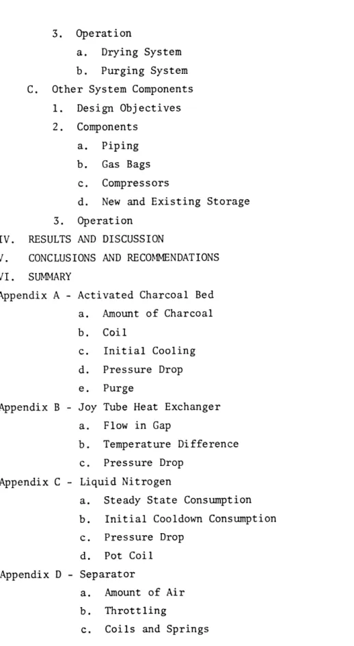
The system selected to meet the design objectives is as shown in Figure 2. Operating conditions chosen for the system are a working pressure of 2000 psi, with drier temperature at ambient and
repurifier temperature at that of LN2.
Repurifier conditions were chosen as optimal based on data reported by A.D. Little Inc. (See Ref. 9)
Drier temperature, at the overall system pressure of 2000 psi, was chosen to be at ambient because decreasing this temperature
does not increase adsorption capacity significantly. This is based on isotherms provided by Union Carbide.
The major components of the helium recovery and repurification system are:
a. The repurifier, which is a unit that accepts high pressure,
dry, impure helium gas, purifies it and pipes the gas to pure storage.
b. The drier, which is a unit that accepts high pressure, water saturated helium gas, removes the water and pipes the gas to impure storage or to the repurifier.
0
0
0
FIGURE 2- HELIUM RECOVERY AND REPURIFICATION SYSTEM
1. Francis Bitter National Magnet Laboratory (NW14) 2. Superconducting Generator Test Facility (N9) 3. Gas Bag, 2000 scf, low pressure impure storage 4. Gas Bag, 200 scf, low pressure impure storage 5. Slave compressor, 30 scfm, 1.0 atm
6. Master compressor, 30 scfm, 2000 psi 7. Drier 8. Impure storage,20,000-40,000 scf 9. Heater 10. Repurifier 11. Pure storage, 111,000 scf 12. CTI 2000 liquefier, 80 L/hr 13. LN2 dewar 14. 10,000 gal LN2 tank
15. 1.0 in., low pressure, copper, impure helium recovery line 16.
½
in., high pressure, S.S., pure helium return line-21-c. Recovery pipelines, which are the lines used to transfer helium
gas between the FBNML and the
CEL.
d. Pure and impure storage capability including a large gas bag.
Each of the system components will be discussed in detail in
following sections. Therefore only a brief discussion is now given.
The repurifier is a high pressure unit capable of accepting dry impure
helium gas at a rate of 50 scfm and at a pressure of 2000 psi. System
flow rates were chosen based on predicted recovery rates. The
repurifier cleans the helium gas using heat exchangers, a separator
and an activated charcoal bed all at LN
2temperature. The repurifier
is cooled using LN
2from an existing 10,000 gallon liquid nitrogen
system, and it has regeneration and gas purity monitoring capability.
The drier is also a high pressure unit, capable of accepting water
saturated helium gas at a rate of 50 scfm and a pressure of 2000 psi.
The drier removes the water from the helium using a bed of molecular
sieve, which is the most effective adsorbent at system conditions.
It does so to prevent water contaminant from entering the storage
tanks or the repurifier, where it could freeze up and plug the system.
It also has oil filtering and regeneration capabilities. The drier
can be run continuously using two adsorber columns run in parallel.
While one column is in operation, the other can be regenerated.
The low pressure line delivers impure helium from FBNML to existing lines at SGTF, from here it goes on to CEL.
The high pressure line delivers pure helium from storage at CEL to FBNML where it is used for experimentation.
The pure and impure helium gas storage consists of existing high pressure gas storage tanks at CEL, approximately 111,000 scf capacity, along with nine new "Jumbo tubes" with a capacity of about 64,000 scf at 1800 psi.
The gas bag stores up to 2000 scf of impure helium at low pressure, which is used as a supplemental feed gas.
-23-C. Operation
A flow diagram of the complete helium recovery and repurification system is shown in Figure 2. Here an overall description of
system operation is given. Detailed operation of each of the system components will be given in following sections. The internal
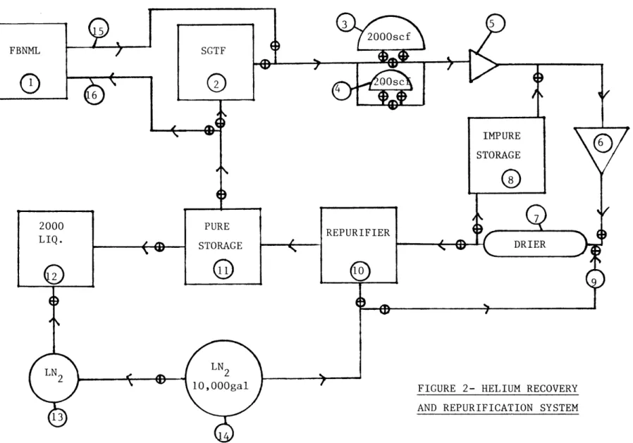
recovery system at FBNML is not part of this thesis, however it is shown in Figure 3 for completeness.
Expended helium gas is recovered from experiments at FBNML (1) and piped through new recovery pipelines (15) to SGTF (2). Here it is sent to CEL via existing piping. The gas can then either be stored in one or both gas bags, an existing 200 scfm bag (4) or the new 2000 scfm bag (3), or it can be sent on to the
existing 30 scfm recovery compressors (5,6) or a combination of both. After compression to approximately 2000 psi the gas goes to the drier (7). Here water is removed using beds of molecular sieve at ambient temperature. After drying, the gas will be sent to impure storage (8). Here it will be stored until enough has accumulated for a repurification run. This will be about 5000 scf, the predicted recovery amount per FBNML run. At this point, the gas will go again through the compressor and
drier and into the repurifier (10). Here it is cooled to LN2
temperature by heat exchangers and an LN2 bath and purified by an activated charcoal bed. The pure gas is sent to pure storage (11). and is ready for reliquefaction or piping to either SGTF or
FIGURE 3- FBNML
-25-The recovered gas is metered using temperature and pressure
changes of the storage tanks. Purity is monitored by taking gas
samples at various points in the repurifier and comparing them
III. SYSTEM COMPONENTS
A. Repurifier
1. Design objectives.
The design goals for the repurifier are:
1. To repurify recovered helium gas with a maximum of 20% water saturated air contaminant, at a rate of 50 scfm and a pressure of 2000 psi, to a contaminant level below 50 ppm by volume.
2. To repurify continuously for a run of 5000 scf before regeneration is needed.
3. To minimize LN2 consumption.
4. To regenerate adsorbers.
5. To monitor purity.
The above design goals place constraints on repurifier components. The components must be of large enough size and strength to accept the volume and pressure of gas specified. Purification must take place under conditions suitable for at least a 50 ppm contaminant
-27-level. Heat leaks and cooled mass must be minimized. And secondary regeneration and purity monitoring systems must be provided.
2. Components
A schematic and detailed flow diagram of the repurifier and its components are shown in Figures 4 and 5. Each component will now be discussed.
a. Activated Charcoal Adsorber.
This is the final step in the repurification process. It will remove any remaining air, particulate matter or other contaminants that have not already been condensed out in the cooling steps.
Charcoal adsorbent was chosen because from the data of A.D. Little Inc. it appears to have a higher capacity for air than other
adsorbents at system conditions. Actually there is little experimental data on the adsorption of air from helium on charcoal. However the data available can be used as a rough estimate of the adsorption performance of charcoal.
The adsorption of air on charcoal is believed to be essentially complete at temperatures near that of LN2 . This is the method
generally used for the removal of oxygen and nitrogen from helium and it is the method used by the Bureau of Mines as the final step in helium purification. The helium produced at the Bureau of Mines contains from 3 to 10 ppm of air.
1. 14 in. O.D., 12 gage, 304 S.S., dished head
2. 14 in. O.D., 12 gage, 304 S.S., rolled cylinder, 3 ft. 3. Nitrogen pot coil
4. Coil springs
5. 8 IPS, SCH.80, 304 S.S. pipe cap 6. Seperator coil
7. 8 IPS, SCH.80, 304 S.S. pipe, 10 in.
8. Upper vacuum jacket lower plate, see figure 19 9. 4 IPS, SCH.40, 304 S.S.pipe, 5½in.
10. O-ring
11. SC 200 load cell
12. Transducer housing lower plate, see figure 23 13. Transducer housing flange, see figure 22 14. 5/8in. threaded rod, 7 in.
15. Top vacuum plate, see figure 16 16. Top vacuum flange, see figure 15 17. O-ring
18. Joy Tube heat exchanger top, see figure 9
19. 30 in. O.D., 10 gage, 304 S.S.rolled cylinder, 7 ft 20. Joy Tube heat exchanger, 2 x 5ft
-31-21. 1 3/4 in., 0.12 in. wall, seamless 304 S.S. tube 22. 2.0 in., 0.049 in. wall, seamless 304 S.S. tube 23. Charcoal adsorber coil
24. 4 IPS, SCH.40, 304 S.S. pipe, 15 ft
25. Joy Tube heat exchanger, bottom, see figure 10 26. O-ring
27. Lower vacuum flange, see figure 20 28. 4 IPS, SCH.40, 304 S.S. pipe cap
29. 8 in. O.D., 0.12in. wall, 304 S.S. tube, 9.5 ft 30. Lower vacuum lower plate, see figure 21
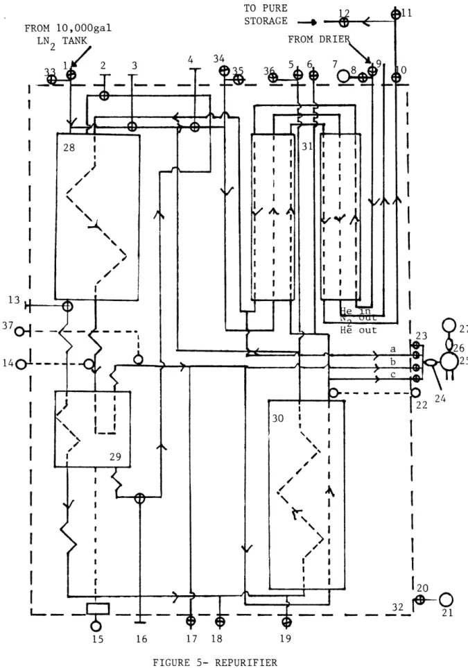
FIGURE 5- REPURIFIER FLOW DIAGRAM 13
37 0
-33-1. 2,3,4. 5. 6,17. 7. 8. 9. 10,11,12. 13. 14. 15. 16. 18. 19,33,35,36. 20. 21. 22. 23. 24,26. 25. 27. 29. 30.
LN2 Fill valve, Whitey 12NBSW8T, 1/2 in.
N2 extended control valve, Whitey 12NBSW8T, 1/2 in. Purge Fill valve, Whitey 12NBSW8T, 1/2 in.
Relief valve, 2000 psi, Circle Seal Line vacuum pump
Pump down valve, Whitey B45S8 ball valve, 1/2 in. Helium inlet, Whitey B45S8 ball valve, 1/2 in. Helium outlet, Whitey B45S8 ball valve, 1/2 in. LN2 extended control valve, Whitey 12NBSW8T, 1/2 in. Vapor pressure thermometer
Data instruments SC200 load cell, Acopian 24 vdc, 0.5 amp power supply
Air condensate extended control valve, Whitey 3NTRS4, 1/4 in.
Purge vent valve, Whitey 12NBSW8T, 1/2 in. Relief valve, 25 psi, Circle Seal
Vacuum Valve Tank vacuum pump
Vapor pressure thermometer
Gas analyzer manifold, 4 Whitey B42S4 ball valves, 1/4 in. Matheson low pressure brass regulator
Gas analyzer, Gow Mac 50-150 Reference gas tank
Separator
Activated charcoal adsorber bed
31. Joy tube heat exchanger
32. Vacuum Jacket
34. N2 Vent, Whitey 12NBSW8T, 1/2 in.
37. Vapor Pressure Thermometer
-35-An appropriate value of the adsorption capacity of charcoal supplied by A.D. Little Inc. is 154 ft3 of air adsorbed per ft3 of charcoal at temperatures near LN2, 1800 psig and 1% air contaminant. (See Ref. 9)
The above value represents the total adsorption capacity,
or static equilibrium capacity, of the charcoal, we are interested in the breakthrough capacity, or the dynamic capacity. The difference between the two values is this. As shown in Figure 6 the
concen-tration of air in the charcoal bed does not change abruptly along it length, it decreases smoothly from saturated at the entrance to pure at the exit. The breakthrough capacity of the charcoal is the amount of air adsorbed at the point where air just begins to appear at the exit of the bed. The adsorption capacity is the total amount of air adsorbed when the exit of the bed becomes saturated with air and cannot hold anymore, air has already been exiting the bed for some time. Since it is required that there be no air in the exit stream of the bed we must use the breakthrough capacity of the charcoal. An es:timate of this
capacity from E.I. DuPont de Nemours is 70 to 80% of the adsorbtion capacity or about 100 ft3 of air per ft3 of charcoal. This value of course changes with bed dimensions and contaminant level, however it appears to be a conservative estimate. (See Ref. 9)
The adsorber was sized, using an adsorption capacity value of 100 ft3/ ft 3, to handle 5000 scf He per run with 20% air contaminant and
5 4 3-- 2- I-o ATURATED FIGURE 6- CONTAMINANT
CONCENTRATION
FCONCENTRATION CONCENTRATION CURVEOF CONTAMINANT
IN ADSORBER ADSORPTION WAVE
I ARBITRARY UNITS 1 2 3 4 5 6 7 1 PURE I I I I I I I BED BED
BED NTNCEDISTANCE ALONG BED BED
-37-contains about 1.3 ft3 of 6-14x mesh charcoal, see appendix A for a brief discussion on this.
This unit consists of a 15 ft lengthof 4 IPS, schedule 40, seamless 304 stainless steel pipe. One 15 ft section is used to facilitate piping. The ends are 4 IPS schedule 40, 304
stainless steel pipe caps drilled through the center to accommodate 3/4 in.ss. tees. These tees are used approximately like heat exchanger tees in order to reduce the number of fittings needed. This can be seen in Figure 7. The branches of the tees inlet and outlet helium while the runs inlet and outlet the N2 cooling
coil. This coil is needed to provide enough surface area for cooling of the charcoal. The •coil is of 1/2 in.stainless steel tubing with an O.D. of 3.5 in.and a pitch of 2.5 in.and about 69 turns. The O.D. was chosen in order to have equal amounts of charcoal in the interior and exterior of the coil turns to ensure constant
temperature throughout the charcoal. A pitch of 2.5 in. was thought reasonable, and it was calculated that at this pitch 69 turns were needed to provide enough coil surface area to completely cool the charcoal and pipe while the unit was operating.
It was also calculated that about 68 liters of LN2 would be needed to initially cool the adsorber. All charcoal adsorber calculations can be found in Appendix A.
HELIUM PATH N2 PATH FIGURE 7- USE OF LARGE TEES A.C.
½"
TUBE
ADAPTER 3/4"TE
-39-negligible.
Since it would be impractical to replace the charcoal adsorbent upon saturation, some means of regeneration must be provided. Regeneration of the charcoal adsorber is done in two steps. First a flow of nitrogen, about 1 scfm, at ambient temperature or heated is passed through the adsorber cooling coil. This warming of the charcoal lowers its adsorbtive capacity so air
is desorbed. Heat up time at 1 scfm is approximately 23 hours. The nitrogen enters and exits through valves (5) and (18), as
shown in Figure 5. By closing valves (3), (4), and (13) the warming flow goes only through the charcoal bed (30), minimizing
heated mass and therefore minimizing the mass needed to be cooled during the next run. Second, the valves (5) and (18) are closed and the adsorber along with the helium flow lines are evacuated using a separate branch of the helium inlet line which was previously valved off (8). Lowering of the adsorber pressure causes desorption due to the decreased partial pressure of the air, which is a major factor in adsorption capacity. After these two steps regeneration should be essentially complete.
b. Joy Tube Heat Exchanger
This is the first step in the repurification process. It will cool the incoming stream to about LN2 temperature so that air or other contaminants can easily be condensed out in the next two steps, the LN2 pot and the separator.
A picture of a Joy Tube is shown in Figure 8. It consists of four concentric copper tubes. Inside the three annuli formed by
the tubes are helical winds of copper ribbon soldered to the tube
walls. These winds form fins which increase the heat transfer area of the Joy Tube.
The incoming helium must be cooled from ambient to about LN2
temperature, by N2 vapor and cold outgoing helium. To do this it was found that approximately a 10 ft length of joy tube would be needed. Calculations can be found in Appendix B. However due to height constraints it was necessary to use two five foot lengths of tube.
With a total 10 ft length, the steady state temperature difference, throughout the heat exchanger between the warm and cold counter-current flows was found to be about 10.170F. This means the incoming stream is 10.170F warmer than LN2 temperature when it exits the
heat exchanger. Therefore the stream will vaporize enough LN2 in the LN2 pot to lower its temperature by 10.170F. The amount of LN2 consumed is approximately 3.5 lb/hr. The N2 vapor produced is then used for cooling.
FIGURE 8 -JOY TUBE
FIGURE 8 - JOY TUBE
I I I C c- _
The pressure drop through the joy tube and pressure jacket gap was found to be negligible compared with the total pressure of 2000 psi.
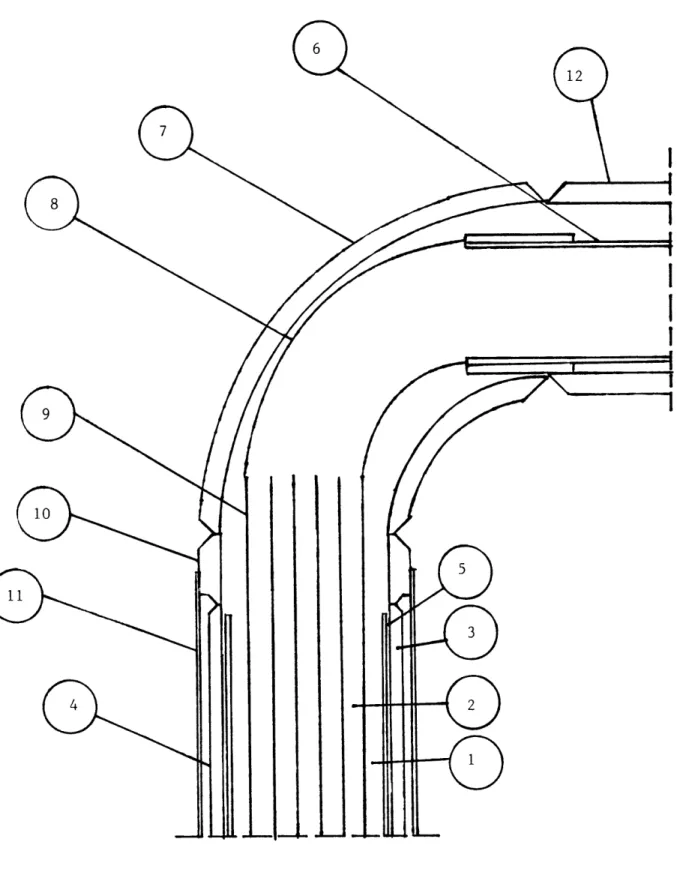
The construction of the heat exchanger shown at its top and bottom ends can be seen in Figures 9 and 10. The incoming warm helium flows through the outermost tube annulus (1) while the cold outgoing helium flows through the two innermost annuli
(2). This scheme was chosen in order to surround the warm helium with cold flow, the cold helium on the inside (2) and on the
outside cooling LN2 vapor from the LN2 pot, which flows through a thin walled 2.0 in. X 0.049 in. wall stainless steel tube
(3) which jackets the outside of the heat exchanger.
Since the joy tube is made of copper and is run at high pressure the heat exchanger must be designed in a way that relieves the
copper of the load. To do this a 1 3/4 in. X 0.12 in. wall stainless steel jacket (4) is put on the outside of the tube. This jacket carries the load of the high pressure inside.
In order to minimize the heat flow resistance of the inevitable gaps that would be found between the joy tube and the pressure jacket, a larger gap, 10 mils wide (5), capable of passing a flow is designed in. The 10 mils was chosen since it would allow easy assembly and pass a reasonable amount of gas without losing the effectiveness of the joy tube. The flow in this gap,
1. Warm helium channel
2. Cold helium channels
3. N2 channel
4. 1 3/4 in. O.D., 0.12 in. wall seamless S.S. tube
5. 10 mil gap
6. 1 1/8 in. O.D. type K copper tube, 6 in. 7. 1 1/2 IPS, SCH 80, long radius, S.S. elbow
8. 1 in. copper to fitting, long radius, copper street elbow 9. Joy tube heat exchanger 5 ft, see Figure 7
10. Adapter, S.S.
11. 2 in. O.D., 0.049 wall seamless S.S. tube 12. 1 1/2 IPS, SCH 80, S.S. pipe 4.5 in.
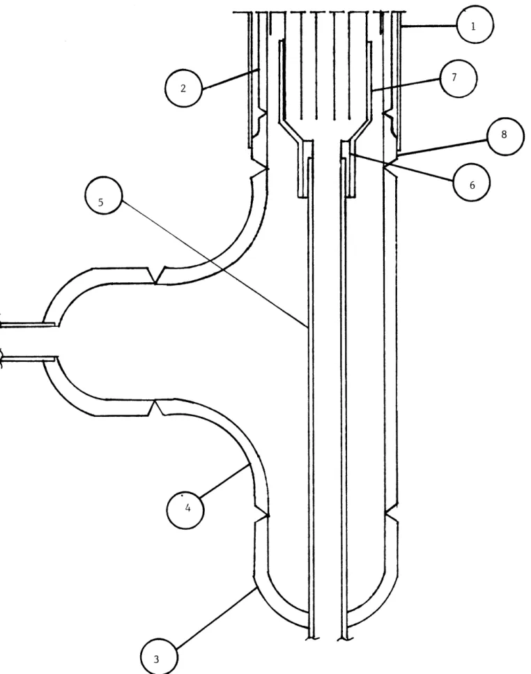
-45-FIGURE 10- HEAT EXCHANGER, BOTTOM
1. 2 in. O.D. X 0.049 in. tube
2. 1.75 in. O.D. X 0.12 in. tube
3. 1 1/2 IPS SCH 80 pipe cap
4. 1 1/2 IPS SCH 80 tee
5. 1/2 in. tube
6. Brass bushing
7. 1 in. to 1/2 in. extended bushing
8. Adapter
-47-between the warm helium (1) and the N2 vapor (3).
The ends of the heat exchanger had to be designed to keep all flows physically separate but in thermal contact. The top end of the heat exchanger, shown in Figure 9, can be seen to be
simply a copper elbow (8) inside a stainless steel elbow (7) and a cold flow copper tube (6) inside a warm flow stainless steel tube
(12). The stainless parts are welded with adapters used to con-nect the various tubes, while the copper parts are soldered. There are no stainless steel to copper joints necessary.
The lower end shown in Figure 10 consists of a stainless steel tee (4). The cold helium flow is carried out of the tee using a piece of 1/2 in. stainless steel tube (5) which is adapted to the joy tube. The warm helium flow fills the tee through the branch and flows into the outside annulus of the joy tube.
The tee is capped with stainless steel pipe caps (3) drilled through the center to accommodate the 1/2 in. tube. There is one stainless to copper joint necessary. It is made using a brass bushing (6) as an intermediate adapter.
c. Liquid Nitrogen Pot.
This is the second step of the repurification process, it will liquify any remaining air or other contaminants. This process of partial condensation is a simple efficient means
of removing the bulk of the contaminants, so that they do not have to be adsorbed. This dramatically reduces the size of the adsorber bed needed.
This unit contains the LN2 used for cooling the repurifier. It is 3 ft tall with a 2 ft O.D. and dished, hemispherical heads at either end. It is made of 12 gage, 304 stainless steel, rolled and welded. The heads are drilled through the center to
accommodate 3/4 in. tees. These tees are used as in the
charcoal adsorber. As shown in Figure 11, the runs of the tees inlet and outlet the helium line. The branch of the top tee allows the flow of N2 vapor in or out of the pot while the lower tee branch allows LN2 to flow out of the pot. Both flows are
controlled by extended valves.
The helium line is coiled inside the pot to increase its heat transfer area, allowing the stream to cool to LN2 temperature causing the air contaminant to condense. The coil is near the bottom of the LN2 pot to ensure its immersion in the LN2, since the pot will not be completely full. The coil has 16 turns a 10 in. O.D. and a 1 in. pitch. These dimensions allow the heat transfer needed to cool the helium to LN2 temperature.
N2 PATH TOP LN2 PATH BOTTOM He PATH FIGURE 11- USE OF LARGE TEES
LN
2 -49-½2" TU ADAPTER 3/4" TEEThe pot is filled through lines from a 10,000 gallon LN2 tank. The LN2 inlet consists of a 1/2 in. tube and a weld adapter used to decrease thermal stressing of the pot head when LN2 is flowing. The adapter is shown in Figure 12. The 1/2 in. inlet tubing is welded at the top of the adapter and enters the head through a drilled hole without touching it.
The pot holds about 9.4 ft3 of LN2 . The amount needed to cool the 5000 scf of helium containing 20% air contaminant plus the repurifier mass is about 5.0 ft 3 , which means the pot will
initially be about half full. More LN2 will probably be needed to account for losses. Calculations can be found in Appendix C.
-51-d. Separator
This unit is the third step in the purification process. Helium and condensed liquid air enter the unit and are separated by gravity. The gaseous helium escapes through the top of the unit while the condensate falls to the bottom.
The liquid air that condenses out in the separator is used to aid in cooling, as opposed to draining it from the system. This increases the system efficiency by reducing LN2 consumption. The condensate is channeled into the N2 vapor line to help cool the heat exchanger. It is controlled by a throttle valve with an extended stem.
The unit consists of a 10 in. length of 8 IPS schedule 80, 304 stainless steel pipe. The ends are 8 IPS schedule 80 pipe caps drilled through the center for tees, and off center for a
LN2 cooling coil line. This coil has dimensions, 5 1/2 turns, 6.5 in. O.D., and 2 in. pitch, and is used to cool the separator mass. The top tee is 3/4 in. It allows the helium to enter
through its run and to escape through its branch. The bottom tee is 1/2 in. It allows liquid air to leave through its branch while its run is used for a connection to a load
cell. This will be discussed a little later.
The cooling coil enters and exits through weld adapters as in the LN2 pot shown in Figure 12.
FIGURE 12- LN2 POT SEPARATOR THRU ADAPTER
-53-In order to know how much liquid air is contained in the separator at any time a load cell is used to weigh the unit. The load cell is a Data Instruments model SC 200, maximum
force 200 lb. The range of weights expected is from 61 lbs empty to 89 lbs full with the liquid air being released when the unit is approximately 1/4 to 1/2 full. The unit will not be allowed to completely fill or empty, so that condensate cannot backup the system causing a pressure increase and so that helium will not become entrained in the throttling system.
The load cell sits in a small housing at the bottom of the upper vacuum tank. Its leads are fed through the bottom plate. The load cell is connected to the separator by a threaded rod which goes from the run of the separator's bottom tee to the top of the load cell. The leads go to a 24 vdc power supply.
In order to weigh the separator it must be allowed to move freely. To do this all lines which constrain the unit have in them coils of tube which act as springs. These springs allow the weight of the separator to be carried by the load cell and not the tubing.
At 20% air contaminant it is estimated that the air will be throttled into the N2 vapor line about every 20 minutes. All separator calculations can be found in Appendix D.
e. Gas Analyzer
It is necessary to know how the repurification process is going and at what point the charcoal adsorber reaches breakthrough. To do this a gas analyzer is used. This unit is a Gow Mac model 50-150 dual pass continuous gas analyzer. It is a
thermal conductivity analyzer meaning it measures the difference in thermal conductivities between a flowing sample and flowing reference gas, and provides an output. This unit is equipped with a 0-1 my high sensitivity meter and a high alarm which
sounds when the contaminant level goes above a set point. It is sensitive to 100 ppm air in helium full scale. A dual pass analyzer is necessary to provide a flowing reference gas, to avoid possible contamination of a static reference.
The analyzer is operated (refer to Figure 5) using a reference gas from a tank (27). This gas is regulated (26) to about 6 psig and 0.01 scfm. The sample can be taken from any one of three points, after the heat exchanger (a), after the separator
(b) or after the charcoal bed (c). This stepwise sampling will show how the purification is progressing. After a sample is chosen using a valved manifold (23) it too is regulated (24), then sent to the analyzer (25) and vented.
The manifold consists of 4 ball valves, three for samples and one spare. The sample and reference flows are regulated by
-55-Matheson low pressure brass regulators and the analyzer's own flow regulators. The analyzer is equipped for all necessary calibration.
f.
Valving and Piping
There are a total of 25 valves on the repurifier. (Refer to Figure 5).
Five of these are extended stem cold valves. There are four Whitey stainless steel 12 NBSW8T 1/2 in. socket weld valves
used, three to control N2 vapor flow (2,3,4) and one for LN2 flow control (13), and one Whitey stainless steel 3NTRS4 1/4 in.
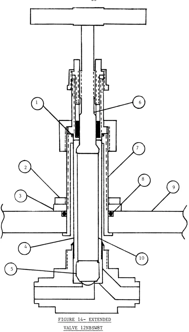
swagelok valve (16) used to throttle liquid air from the separator. Schematics of the two types of extended valves can be seen in Figures 13 and 14.
There are four more 1/2 in. socket weld valves used as fill valves. One to inlet LN2 to the LN2 pot (1), two to inlet and outlet the purge stream (5, 18), and one N2 vent (34).
There are six Circle Seal relief valves. Two of these valves are high pressure (2000 psi) used to relieve the helium stream before (17) and after (6) the charcoal bed in case of a pressure buildup. The other four valves are low pressure (25 psi) used on the N2 cooling lines. They are placed before the charcoal bed (19), at the N2 exit of the LN2 pot (35), at the N2 exit of the charcoal bed (36), and on the LN2 fill line (33).
There are nine Whitey ball valves used. Four B42S4 , 1/4 in. swagelok valves are used for the gas analyzer manifold (23).
-57-FIGURE 13- EXTENDED VALVE- 3NTRS4
1. 2. 3. 4. 5. 6. 7. 8. 9. 10. FIGURE 13 (CON'T) O-ring Top plate
1/2 in. X .028 in. 304 S.S. tube 1/4 in. X .028 in. 304 S.S. tube Cut valve stem
Valve stem w/o back seat Tightening nut
Spacer O-ring Adapter
-59-FIGURE 14- EXTENDED VALVE 12NBSW8T
i. O-ring
2. Tightening nut
3. Spacer
4. 7/8 in. X 0.035 in. 304 S.S. tube
5. Cut valve stem, bottom
6. Cut valve stem, top
7. Adapter
8. O-ring
9. Top plate
10. 11/16 in. X 0.020 in. 304 S.S. tube
-61-The remaining five ball valves are B45S8s. Four of these are used as the inlet (9) and outlet (10, 11, 12) for the helium stream, while the fifth (8) valves the connection for the line vacuum pump.
The final valve (20) is a Vacuum valve used on the vacuum jacket pump down line.
Most of the repurifier piping consists of 1/2 in. O.D. seamless 304 stainless steel tubing. This was chosen to cut down on line pressure drop. The condensed air lines consist of 1/4 in. O.D. tube and the gas analyzer line is 1/8 in. O.D. tube. The
1/8 in. tube was chosen to create pressure and temperature drops in the line before entering the analyzer.
All repurifier internal fittings are stainless steel socket weld.
g. Vacuum Jacket
This is the outer jacket of the repurifier. It contains all other components. The other components are suspended and all feedthroughs go through the top of this jacket. The jacket is evacuated to thermally isolate the components. It is constructed mainly of stainless steel in order to minimize corrosion problems and outgassing problems due to the vacuum. The complete vacuum jacket is made of three parts, the upper
jacket, lower jacket and transducer housing.
The upper jacket consists of a 30 in. O.D. 10 gage rolled 304 stainless steel tank, seven feet in length. At the top of this tank is welded a flange, 34 in. O.D., seen in Figure 15. The flange is used to bolt on the upper plate and as a seat for an o-ring.
The top plate, 5/8 in. thick, as seen in Figure 16, contains all the repurifier feedthroughs except the vacuum connection which is a 1 in. tube welded into the side of the upper jacket. The top plate also contains threaded holes for lifting eyes, and suspension rods. All connectors are made through this plate to facilitate repurifier assembly.
From Figure 16 we see that there are two types of weld preps. On the C and D holes an o-ring is used as a seal. An
FIGURE 15 - TOP VACUUM FLANGE
_~._ I I __
FIGURE 15 - TOP VACUUM FLANGE
I
ON0
0
BREAK EDGES
r= 0.
2"
used for the extended valves. Their setup can be seen by referring back to Figures 13 and 14. This setup is used in order to allow for the possible removal of the valves at some
later time. The valves can be easily assembled or disassembled by means of a tightening nut.
On the A and B holes, an example of an A hole is shown in Figure 18, grooves are machined and tubes are welded into the holes. On the top of the tubes are welded adapters which accept whatever
is being fed through. These adapters are shown in Appendix F. This scheme isolates the feedthroughs to prevent freezeup of the plate. They are more permanent setups than the C and D holes since the removal of one of these feedthroughs calls for cutting or grinding of welds.
At the bottom of the upper jacket is welded a plate 5/8 in. thick shown in Figure 19. This plate contains two through holes, 4 in. and 7.75 in. O.D., with threaded bolt holes, 1/4 in.-20, 1/2 in. deep, where the lower jacket and transducer housing are attached.
The lower jacket is needed to jacket the 15 foot charcoal bed. It consists of a welded flange 10 in. O.D., shown in Figure 20, used to attach it to the upper jacket and as a seat for an o-ring seal. An 8 in. O.D., .12 in. thick 9.5 ft long stainless steel tube used as the lower tank, and a lower plate welded to the lower tank and shown in Figure 21.
PLATE
00
FIGURE 20 - LOWER VACUUM FLANGE
-71-The transducer housing is a separate, removable jacket which makes the load cell easily accessible in case of problems.
It consists of a welded flange 6.5 in. O.D., shown in Figure 22, also used for attachment and an O-ring seal. A 4 IPS schedule 40, 5 1/2 in. length of stainless steel pipe used as the housing, and a lower plate welded to the housing and shown in Figure 23. In the lower plate is machined a groove where the
load cell sits. This groove keeps the load cell from sliding in the housing. Load cell leads are fed through the lower plate.
Stress and collapse calculations for the vacuum jacket can be found in Appendix G.
N ·il ;i e :i i: i:.
0
0
0
0
*
0
nD__ TRNC - i N FEEDTHRI FOR LOADCI GROOVE FOR LOADCELLFIGURE 23- TRANS. HOUSING LOWER PLATE
It
3. Operation
Refer to flow diagram Figure 5.
a. Repurification System
The impure helium enters the repurifier from the drier through a ball valve (9). The helium then goes through two five foot lengths of Joy Tube heat exchanger (31). It travels through the outer annulus of the joy tube being cooled by N2 vapor contained in an outside jacket and cold pure helium which is exiting the repurifier via the inner two joy tube annuli.
At this point the helium should be near LN2 temperature. Its purity level can be checked by the gas analyzer (25) by opening the correct sample ball valve (23).
Now the helium proceeds to the LN2 pot (28) and is cooled to LN
2
temperature in the cooling coil. Here the air contaminant will condense out of the gas and be carried into the separator (29) where the
condensate is separated from the gas by gravity.
The helium exits the top of the separator and again can have its purity level checked by the manifold (23).
-75-valve (17) is connected at the bed entrance to prevent overpressurization
of the bed. Here all residual contaminants are removed from the helium.
Upon exiting the bed helium purity can again be checked by opening the
manifold (23). Another 2000 psi relief valve (6)
is placed at the
exit of the bed to prevent heat exchanger overpressurization in case
of clogs.
The cold pure helium now enters the inner two annuli of the heat
exchanger and cools the incoming helium. The warm pure helium
exits the repurifier through a ball valve (10) and is sent to
b. Cooling system
The cooling system begins with the LN
2pot being filled from storage
thru valve (1).
Some of the LN
2is vaporized by the incoming helium
and pressurizes the cooling system. A low pressure 25 psi relief
valve (33) is installed to prevent pot overpressurization. The
LN
2flows from the bottom of the pot through an extended stem control
valve (13) to the separator cooling coil. Another 25 psi relief valve
(19) is placed in the line here.
From here the N
2enters the charcoal bed cooling coil. Upon exiting
the bed the N2 flow is again relieved by valve (36).
At this point the N
2flow may either be sent back to the LN2 pot via
valve (3)
or it can be sent on to the heat exchanger via valve (4).
If sent to the heat exchanger the N
2vapor can be supplemented with air
condensate from the separator by opening throttle valve (16).
It can
also be supplemented with more N
2vapor from the top of the LN
2
pot via valve (2).
Whichever combination is chosen the cooling stream is relieved at the
heat exchanger entrance, flows through the outer jacket and upon
-77-c. Purging system
The purging system consists of a warming stream of nitrogen.
This nitrogen can be at ambient temperature or heated. This stream enters the repurifier through a fill valve (5) and goes into the charcoal bed cooling coil. Valves (3) and (4) are closed to confine the purge stream to the charcoal bed. The stream goes through the coil warming the bed. When the stream exits the bed it is again forced, by the closing of valve (13), to exit the repurifier through valve (18) and vent to the atmosphere.
The warming stream is allowed only in the charcoal bed to minimize the mass heated up and therefore the mass needed to be cooled during the next run.
At this point all internal valves are opened and all other valves closed. Now the entire system is evacuated through a ball valve
(8) in a branch of the helium inlet line. This evacuation lowers the partial pressure of the contaminant causing desorbtion and removes any other contaminant from the system.
After desorbtion is complete the repurifier is recooled and ready for normal operation. Purge flow rate and time are roughly 1 scfm of N2 for 23 hours at ambient temperature. Calculations can be
B. Drier
1. Design Objectives
The design goals for the drier are:
1) To remove moisture from recovered helium gas at a rate of 50 scfm
at 2000 psi.
2) To attain a contaminant level below 50 ppm by volume.
3) To regenerate adsorbers.
4) To run continuously by using 2 adsorbers in parallel.
These goals require the unit to be of adequate size and strength to accept the volume and pressure of gas specified. They require high quality adsorbent, to attain the desired purity level, along with piping connections and a secondary purging system which can be used by one adsorber while the other is in operation.
-79-2. Components
A detailed flow diagram of the drier is shown in Figure 24. Each component will now be discussed.
a. Cylinders
As seen in Figure 24 there are two cylinders run in parallel. This is so that the drier can be run continuously by simply switching adsorber cylinders. It eliminates the problem of coordinating drier adsorber and charcoal adsorber regeneration cycles.
The cylinders used are Robbins Aviation Inc. purifier chambers model 10ASP with a maximum flow rate of 525 scfm and a maximum pressure of 10,000 psia. These cylinders are used because of their appropriate specifications and availability. A schematic of a cylinder is shown in Figure 25.
The cylinders have internal end threads at each end which accept
threaded end plugs. These plugs have integral O-ring grooves used for sealing the cylinders. All connections are made in the top plug. It has inlet and outlet connections which use swagelok O-ring fittings for sealing.
On the cylinder side of the inlet in the top plug is another O-ring
FROM IMPURE STORAGE
VENT
REPURIFIER
FIGURE 24- DRIER FLOW DIAGRAM
N2 VENT
FROM 1C LN2
TO IMPURE STORAGE
-81-1,2. Evacuation valve, Whitey B44S6 Ball valve, 3/8 in.
3. Condensate trap
4. Vacuum pump
5,6. N2 vent valve, Whitey B44S6 Ball valve, 3/8 in. 7,8. Adsorber switching valve, TOP, Whitey B44S6 Ball
valve, 3/8 in.
9,10. Adsorber columns
11,12. Adsorber switching valve, BOTTOM, Whitey B44S6 Ball valve, 3/8 in.
13,14. N2 inlet valve, high temp. Whitey 6TS6, 3/8 in. 15. Heater, Hotwatt 12 in., 120 vac. 20 amps
16 Back pressure regulator, Grove S-91-W
17 Storage valve, Whitey B44S6 Ball valve, 3/8 in.
9
(
\j2
14
15OUHELT
OUT
FIGURE 25- DRIER CYLINDER SCHEMATIC
7 8
C
~ C, ~ rr rrrr2
3
-83-1. Bottom end plug
2. O-ring 3. Cylinders 4,13. Spacers 5,8. Filter material 6. Molecular sieve 7. 1/2 in. tube 9. O-ring
10. Top end plug
11,15. Swagelok O-ring fitting
12. O-ring
14. O-ring
in the drier, instead loose molecular sieve pellets are used, but the O-ring will be used to seal the 1/2 in. helium inlet tube.
-85-b. Molecular Sieve
Molecular Sieves belong to a class of compounds known as zeolites.
Zeolites are naturally occuring, however they are scarce and
there-fore synthetic zeolites are generally used. They are crystalline
metal alumino silicates that are activated for adsorbtion by
removing their water of hydration with heat. This removal causes
little change in compound structure and therefore a very porous
adsorbent is formed with a strong affinity for water and certain
gases.
(see reference 4).
The pores of molecular sieve are uniform in size and of molecular
dimensions. This allows for a high selectivity on the basis of
molecular size. However once a molecule is admitted, its volitility,
polarity and degree of unsaturation also play a part in how tightly
the molecule is held. These properties along with a high adsorption
capacity make molecular sieve a very efficient adsorbent.
The pores of molecular sieve type A which is used in this project
are roughly spherical and about four angstroms in diameter (see
reference 4).
This pore size makes this sieve especially good for water adsorption.
These pores account for about half of the total adsorbent volume.
The strong adsorption forces in molecular sieves are due mainly to
attract negative charges on polar molecules such as water and
can induce dipoles in non-polar molecules. Of course the more
polar the molecule the more strongly it is attracted. Molecular
sieves are characterized by langmuir type isotherms in which
adsorption capacity increases to a saturation point and then
remains level. This saturation point corresponds to the
filling of the sieve internal voids.
This type of adsorbent was chosen over silica gel etc. because
of its high drying efficiency. It has been reported to dry gas
to a water content of 0.05 ppm by volume.
An estimate of adsorption capacity is given by Union Carbide
Linde Div. data sheet F-43A-1 as 20 lbs of water adsorbed per
100 lbs of molecular sieve type 4A pellets at drier conditions.
Using 10 lb/lb as a conservative estimate of breakthrough capacity,
as explained in section IIIA, la, it is found that 15 in.
of
sieve is needed per hour of run at 50 scfm, water saturated
helium. All molecular sieve calculations can be found in Appendix E.
Therefore a full cylinder holding about 165 in. of sieve will last
for 11 hours of operation before regeneration is needed.
The pressure drop through the drier bed is negligible compared to
-87-Purging of this unit is done using heated dry nitrogen gas from the 10,000 gallon LN2 tank @ 30 psi, and evacuation. When one of the cylinders is saturated the helium flow is switched to the other cylinder. The dirty cylinder is then heated by a counter-current flow of nitrogen at 5 scfm and 5000F, regulated by the vent valve. The nitrogen is heated using a Hot Watt Inc. 2.4 kw, 12 in. standard air heater. Its temperature is controlled using a surface mount thermostat and relay as a thermoswitch. The temperature and flow of the nitrogen were recommended by Union Carbide. The bed reaches 5000F after about 1.25 hours. At
this point the nitrogen flow is stopped and the bed is evacuated. This method of regeneration is in principle the same as that used in the charcoal bed.
c. Cylinder Interior
Aside from the molecular sieve (6) the cylinder interior contains tubing, filtering material and spacers. These can be seen in Figure 25.
The tubing (7) is put on the interior inlet port and runs to the bottom of the cylinder. This tube, which is sealed by an
O-ring (14), carries the helium to the bottom of the bed.
Filtering material (5,8) such as glass wool is put at the ends of the cylinder to filter out any oil that gets thru the oil separator and to keep the sieve from flowing out of the cylinder. Glass wool is needed due to the high bed purging temperature. Spacers (4,13) are provided to support the bed and to keep the
-89-d. Valving and Piping
There are twelve valves used with the drier. They can be seen in Figure 24. Nine of these valves are Whitey 3/8 in. swagelok
Ball valves. These valves are used for storage, purge flow control and cylinder switching. There are two Whitey high temperature valves (13,14) also 3/8 in. swagelok. These are put on the purge lines where the hot nitrogen enters the cylinders. And the last valve (16) is a Grove back pressure regulator which holds the drier pressure when helium is being sent to impure storage.
The drier piping consists of 3/8 in. O.D. 304 stainless tubing for all lines that are at working pressure. The 3/8 in. lines match up with existing system lines. The purge lines consist
of 1/2 in. copper lines. These lines are at low pressure. They extend up to the valves which separate them from the high pressure system.
Drier fittings are 3/8 in., stainless, swagelok for the high pressure line and solder fittings for the low pressure line.
3. Operation
Refer to flow diagram Figure 24 and Figure 25.
a. Drying System
The helium enters one of the drier cylinders (9 or 10) from the recovery compressor and oil separator thru a ball valve (7 or 8). The helium is carried to the bottom of the cylinder by an internal tube. From here it flows upward thru the filter material and molecular sieve and is dried. The dry helium flows from the
cylinder thru another ball valve (11 or 12) and then either to the repurifier or to impure storage. This continues until the
cylinder is saturated with water at which time the cylinder is valved off and the other cylinder is opened for operation.