HAL Id: hal-00596968
https://hal.archives-ouvertes.fr/hal-00596968
Submitted on 30 May 2011HAL is a multi-disciplinary open access
archive for the deposit and dissemination of sci-entific research documents, whether they are pub-lished or not. The documents may come from teaching and research institutions in France or abroad, or from public or private research centers.
L’archive ouverte pluridisciplinaire HAL, est destinée au dépôt et à la diffusion de documents scientifiques de niveau recherche, publiés ou non, émanant des établissements d’enseignement et de recherche français ou étrangers, des laboratoires publics ou privés.
FIBER RING RESONATOR BASED
OPTO-ELECTRONIC OSCILLATOR - PHASE NOISE
OPTIMISATION AND THERMAL STABILITY
STUDY
Khaldoun Saleh, Aude Bouchier, Pierre-Henri Merrer, Olivier Llopis, Gilles
Cibiel
To cite this version:
Khaldoun Saleh, Aude Bouchier, Pierre-Henri Merrer, Olivier Llopis, Gilles Cibiel. FIBER RING RESONATOR BASED OPTO-ELECTRONIC OSCILLATOR - PHASE NOISE OPTIMISATION AND THERMAL STABILITY STUDY. Photonics West 2011, Jan 2011, San Francisco, United States. 10p. �hal-00596968�
FIBER RING RESONATOR BASED OPTO-ELECTRONIC
OSCILLATOR - PHASE NOISE OPTIMISATION AND THERMAL
STABILITY STUDY
K. Saleh
a, b, c, A. Bouchier
a,b, P.H. Merrer
a,b, O. Llopis
a,b, G. Cibiel
ca
CNRS ; LAAS ; 7 avenue du colonel Roche, F-31077 Toulouse, France
b
Université de Toulouse ; UPS, INSA, INP, ISAE ; LAAS ; F-31077 Toulouse, France
cCNES, 18 avenue Edouard Belin, F-31401 Toulouse, France
ABSTRACT
In the microwave domain and among many other advantages, optics represents an elegant solution to increase the quality Q factor in a system. Different types of optical resonators lead to Q factors above 109, and these resonators can
be used as an alternative to optical delay lines to set up the frequency in optoelectronic oscillators (OEO). However, microwave-optics is also a complex field, and if the use of optical resonators in high spectral purity frequency generation systems like OEO has been already demonstrated, many aspects of these OEOs are still incompletely understood, especially the contribution to the oscillator phase noise of the different optical and microwave elements used in the oscillator system. In order to improve the phase noise of a fiber ring resonator based OEO, this oscillator has been theoretically studied in term of white frequency noise. In this paper, we present a theoretical study that has lead us to optimize a fiber ring resonator and the experimental phase noise results obtained for an OEO based on an optimized optical resonator. The OEO thermal stability is also investigated in this paper.
Keywords : Opto-electronic oscillator, fiber ring resonator, quality factor, phase noise, thermal stability.
1. INTRODUCTION
The best microwave oscillators are actually based on microwave (electromagnetic) resonators with quality factors that can reach 105 at 10 GHz in case of sapphire whispering gallery modes WGM resonators. However, these resonators have
their own limits: their performances degrade at high frequencies (millimetre range) and their size is prohibitive in the low microwave range (~ 5 GHz). Thus, the design of new compact and high performances oscillators is linked to the investigations on new resonators.
An elegant method to reduce the oscillator dimensions and/or to increase the Q factor is to carry the microwaves on another wave type, like acoustic or optical waves [1]. The use of an optical carrier is common to take benefit of optical delay lines properties. These lines are few-km-long optical fibers, with equivalent RF quality factors that can reach 106 at
10 GHz and they have been used to stabilize oscillators [2]. Although they are easy to use and relatively well-known, they remain bulky and their thermal stabilization is difficult. An alternative solution to fiber delay lines is the use of optical resonators, with higher Q and relatively low dimensions due to the resonant effect. It is thus possible to design new devices featuring better performances than classical microwave devices.
In the case of optical resonators, one solution is very similar to high Q microwave resonators: the use of optical WGM resonances. These devices are spheres, torus or disks, in which the optical wave circulates close to the equator line. They present really high optical quality factors with demonstrated values from 108 to 1011 at 1.55 µm [3], but their use in a
system is delicate, particularly the coupling of the optical carrier to the resonator via an optical fiber or a prism... Another approach is to take benefit of the low losses in optical fibers to realize a high Q resonator, and we present here the principle and use of high Q fiber ring resonators and OEOs.
RF and Millimeter-Wave Photonics, edited by Robert L. Nelson, Dennis W. Prather, Christopher A. Schuetz, Proc. of SPIE Vol. 7936, 79360A · © 2011 SPIE · CCC code: 0277-786X/11/$18 · doi: 10.1117/12.873755
To predict the efficiency of fiber ring resonators in terms of quality factors and phase noise when they are included in an optoelectronic oscillator (OEO), a simulation tool is presented in this paper. An optimization approach of the white frequency noise contribution, an extension to the OEO case of a classical method used for microwave oscillators, [4], is also proposed. The experimental results obtained on the OEO phase noise with a new optimized resonator are presented.
Finally, a theoretical and experimental study has allowed us to determine precisely the oscillator thermal stability, which is an essential parameter for our applications.
2. FIBER RING RESONATOR AND OPTOELECTRONIC OSCILLATOR
2.1 ) Fiber ring resonator
Optical telecommunications has leaded to the development of optical fibers that allow us to build easily an optical resonator using two low loss fibered couplers linked with single-mode fibers (Fig. 1). This resonator will thus generate a transverse single frequency comb with a microwave spacing, free spectral range (FSR), which is directly related to the resonator dimensions. Thanks to the compatibility with pigtailed lasers, the coupling of the optical carrier to the optical resonator is stable and the system can be potentially integrated in a compact device.
Figure 1. Scheme of the fiber ring resonator and resonant modes in transmission and absorption.
If the coupling factor is chosen small enough, and if the residual losses of all elements (couplers, splices) are low enough, this optical resonator will feature a high optical factor. Because of the comb type spectral response of this resonator, we can take benefit of this Q factor also in the microwave range using two or more modes, and the equivalent RF quality factor in this case can be written as:
. (1)
where fRF and fopt are respectively the RF and the optical frequencies.
This relation shows that the RF equivalent quality factor increases with the RF frequency for a fixed optical frequency. Nevertheless, and to reach quality factors higher than those obtained with microwave resonators, should be higher than 109 because of the frequency ratio, , which is as low as 10-4 for an optical carrier at 1.55 µm (around
194 THz) and a microwave signal at about 20 GHz. With such a challenging optical Q factor, these optical resonators can lead to an elegant alternative to microwave resonators. Moreover, due to the fiber low thickness, the fiber resonator features a planar shape which can be easily integrated in a system.
2.2 ) Optoelectronic oscillator
The OEO we have built thanks to this fiber ring resonator is schematically described on Fig. 2 and has been fully described in [5].
Figure 2. Principle of the optoelectronic oscillator at 10 GHz.
The laser used in this OEO configuration has a very thin linewidth and is stabilized on a resonance using a low frequency Pound-Drever-Hall (PDH) feedback loop [6]. The microwave oscillation is then maintained by another HF loop containing a microwave filter, an amplifier and a phase shifter.
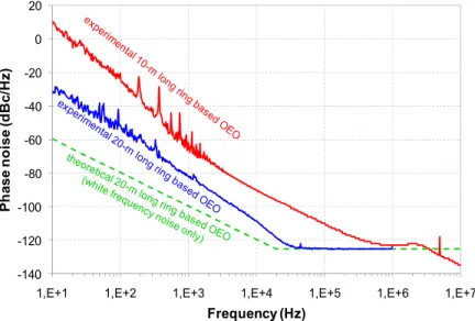
In our first OEO configuration, and in spite of a relatively good loaded quality factor of our first 10 meter fiber ring resonator, the OEO presented a high phase noise level (Fig. 3). This high phase noise level was firstly due to the losses through the resonator, which degrades the optical link noise to carrier ratio (NCR . The NCR influences directly the white frequency noise part of the oscillator phase noise spectrum (between 2 kHz and 500 kHz on the upper curve of figure 3. Reducing the transmission losses through the resonator is difficult, because this parameter is directly related to the coupling factor of the two optical couplers, and thus to the loaded quality factor. An increase of the coupling may degrade the Q factor and the phase noise.
Closer to the carrier, another noise component of high amplitude, this time of 1/fα type (α > 1), was also observed.
This 1/fα frequency noise may be due to the resonator itself or to the laser PDH stabilization loop, which was not
optimized for low noise operation.
However, for the white frequency noise part of the spectrum, the noise contributions can be more easily calculated as they are related to the noise to optical carrier ratio NCR. A theoretical study of the contribution of the optical resonator to the white frequency noise has thus been performed.
Figure 3. Phase noise measurements for the 10m-long fiber ring based OEO (in red), and the new 20m-long fiber ring based OEO (in blue). The green dashed curve shows the théoretical contribution of the white frequency noise of the 20m-long ring on the OEO
phase noise [7] ; measurements are performed on an Agilent E5052B signal source analyser. -140 -120 -100 -80 -60 -40 -20 0 20
1,E+1 1,E+2 1,E+3 1,E+4 1,E+5 1,E+6 1,E+7
P h a s e nois e (d Bc /Hz) Frequency (Hz)
3. OEO WHITE FREQUENCY NOISE OPTIMISATION
The theoretical study of the OEO occur in two steps: we had first modelled the resonator itself and then its influence on the oscillator phase noise [7].
3.1 ) Fiber Ring Resonator and OEO white frequency noise modeling
The fiber ring resonator was modelled in terms of electrical fields [8], and described through its length and optical couplers characteristics in terms of transmission (T), coupling (κ) and losses (p) coefficients. We also take into account the intrinsic losses (α) of the ring such as splicing losses (Fig. 1). With this model, we can predict the resonator FSR, the mode width and thus the optical quality factor of the resonator.
The OEO white frequency noise contribution, resulting from the optical noise to carrier ratio is then evaluated. Inside the OEO loop bandwidth, it depends on the offset frequency , the optical quality factor and the noise to carrier ratio NCR as shown in relation (2).
20. log
2. √2. . 10. log (2)
This model is of course only valid in the frequency range on which the phase noise is dominated by the white frequency noise contribution (additive noise effect).
3.2 ) Fiber Ring Resonator optimization and new OEO phase noise results
The factor of the fiber ring resonator and its contribution to the OEO phase noise are closely linked to the fiber length, the optical couplers residual losses and the intrinsic losses of the ring itself. A decrease of the fiber ring losses and of the coupling factors of the optical couplers will increase . However the decrease of the coupling factors will also degrade the carrier to noise ratio. Therefore, a trade-off has to be found between high loaded and low NCR to obtain the best results in terms of OEO phase noise using equation (2).
Thanks to this theoretical study [7], we have designed a new optimized fiber ring resonator of 20m long, using a couplers coupling ratio of 99/1 %. This resonator has been characterized using a measurement set-up described in [5]. A high spectral purity laser (Koheras) is firstly locked on the resonator with the PDH approach, and then the lateral resonant modes are studied using a microwave modulation of the laser signal using a Mach-Zehnder modulator. With this approach, it is easy to get the frequency response of the resonator with an extreme precision, as the analysis is performed using a microwave network analyser. With this technique, a mode width of 38 kHz has been measured on this new resonant device, and thus an optical quality factor of 5.1x10⁹ at 1.55 µm. With this measurement, and thanks to our
theoretical model, we have been able to estimate the splice losses to be 0.01 dB and the couplers residual losses to be 0.04 dB. Using these characteristics of the fiber ring resonator, the contribution of the white frequency noise is expected to reach a level of -120 dBc/Hz at 10 kHz from the carrier (Fig. 3), taking into account that a relatively low laser power has been used in this experiment in order to prevent any unwanted behaviour such as the starting up of Brillouin generation or of any nonlinear behaviour of this kind.
This new 20m long fiber ring resonator has been used to realize a new OEO at 10 GHz and the related phase noise has been measured (Fig. 3). We can observe that the phase noise level has effectively been improved with a level of -110 dBc/Hz at 10 kHz from the carrier, and about -30 dBc/Hz at a 10 Hz offset frequency. The corner frequency at the frontier between the white frequency noise and the phase noise floor confirms a RF quality factor of 2.5x10⁵ at 10 GHz
for the OEO. Compared to the previous result, the improvement is clear, both for white frequency noise or 1/f frequency noise. However, a clear to 1/f noise contribution is still observed inside the resonator bandwidth. Further improvements in phase noise will need a better understanding of this noise contribution.
3.3 ) Resonator and OEO simulation using ADS
The new experimental phase noise result has shown that the white frequency noise contribution is not predominant any more, as it is clearly demonstrated through the comparison of the computation based on the NCR model and the experimental data (Fig. 3). We have now to model the 1/f noise conversions in this system. This 1/f frequency noise
may come from the resonator (resonator frequency fluctuations) or may be due to the conversion process in the oscillating system, or even inside the resonator itself, of another source of 1/f noise. Our approach of this problem is based on an original method developed on ADS software (Agilent) [9]. Indeed, ADS is able to simulate the non-linear noise conversions between carriers at frequencies which are totally different, such as DC, RF carrier (ex : 10 GHz) and its harmonics and the optical carrier (194 THz). This software also includes system models of classical microwave devices, circuit modelling capabilities and the possibility to develop our own models of optical devices (even if it is not an optical simulator) using black box approach.
Using ADS, we are now able to simulate the optical and RF response of the optical fiber ring resonator. This model is based on a description of the resonator using ideal transmission lines (defined by their delay, losses…) and couplers models included in ADS. It has been compared to an analytical model developed on Matlab for these resonators [10], and also to experimental results. In both cases, the comparison has proven the efficiency of our approach on ADS software. It is a real improvement of our approach, because already at resonator level, it is much easier to simulate using ADS than on a specific model developed on Matlab. Indeed, ADS offers a modern circuit design interface which allows quick changes in the resonator configuration and the possibility to simulate complex resonators (such as coupled resonators for example).
The resonator model has then been included in an optical link model also developed using ADS [9]. The RF response of the resonator can thus be simulated in an open loop configuration (including some noise conversions). Then the optical link with the resonator has been included in a complete OEO system and the oscillating loop has been closed adding an element which allows the control of the phase, the gain, and which also filters the signal with the same Q factor as the dielectric resonator used in the real OEO experiment (Q ~ 2000, which is enough to select one mode of the resonator frequency comb).
Thanks to the resonator simulation approach, we have now a better understanding of some noise conversion phenomena. The laser noise can be converted in this type of resonators, and it could be the main problem in these systems. However, the results obtained on the whole system are not, up to now, totally in agreement with the experiment and we are still investigating on this modelling approach. The complete modelling approach of the OEO using ADS will thus be presented in a further paper.
4. FIBER RING RESONATOR AND OEO THERMAL STABILITY
One of the critical points in the use of OEOs is their thermal stability. Because the resonator is the frequency reference element in the OEO, the oscillator thermal stability is directly related to the resonator thermal stability. More precisely, it is the frequency stability of the modes spacing, rather than the absolute optical frequency, that has to be studied. We have thus investigated on this problem both theoretically and experimentally, and both on the resonator alone and on the whole OEO system.
4.1 ) Theoretical study
The mode spacing in the resonator frequency comb, FSR, is given by , where is the speed of light, is the optical fiber effective refractive index and is the fiber length. Thus, the mode spacing will depend on these two parameters of the optical fiber used in the resonator, n and L.
In our model, we have considered that the fiber encounters a temperature variation of . The variation of the effective refractive index with the temperature will be more important than that of the fiber length in a typical single mode silica fiber. It has a nearly linear dependence on temperature, [11], and it is given by:
∆ 9.2 10 ∆ (3)
The fiber length variation is related to the fiber expansion coefficient α, [11] [12], by:
α 1
L 0.5 10 (4)
Thus, the fiber length variation with the temperature will be given as follow:
∆ 0.5 10 L ∆ m (5) In a fiber ring resonator, the optical field phase delay, after propagating though the fiber loop [13], is given by:
φ 2π ϑ n L
c (6)
where ϑ is the optical frequency and the resonant frequency ϑ will be determined by: 2π ϑ n L
c 2kπ (7)
Thus ϑ will be as follow:
ϑ k c
nL k FSR (8) From (8), we can see that the optical resonant frequency is a multiple k of the resonator free spectral range.
When heating the fiber in the ring, and will change with , so that the optical signal will encounters an additional phase delay , given by :
∆φ 2п ϑ L ∆n n ∆L
c (9)
And the condition (6) will be replaced by:
φ 2π ϑ nL
c ∆φ (10)
The kth resonant frequency ϑ will then shift by ∆ϑ as follow:
∆ϑ c k L ∆n n ∆L
nL Hz K (11)
From (11), we can see that a first effect of the thermal variation in a fiber ring resonator will be a uniform shift of the frequency comb generated by the resonator. Together with this effect, the will also change, and this is the only variation in the optical domain that will be visible in the RF domain, because in a microwave application the photodiode output will be the resulting RF frequency of the beating between two optical modes of the frequency comb.
This variation is given by:
∆FSR c L ∆n n ∆L
nL Hz K (12)
From (11) and (12), we get:
∆ϑ k ∆FSR (13) The figure 4 shows a simple illustration of some relations mentioned above.
The calcu represented i
Figu
As we ca fiber ring len because in ou we will have get the globa
Thus, From (14 where, Figure 4. ulated FSR va in figure 5. ure 5. Théoretic an see from fi ngth, so that t ur RF applicat e to multiply th al FSR variatio 4) and (15) we Relation betw ariation, ∆FSR cal FSR variatio igure 5, the F the longer the tions we use t his result by a on, ΔFSRRF , ( e can conclude -3000 -2500 -2000 -1500 -1000 -500 0 0 Δ FSR (HzK -1) een frequency s R, for differen on with a total h SR variation e fiber ring is two modes of a number N of (Fig.4). This n N= ΔFSR e: ΔFSRRF =( 1 2 3 4 5 6 Fib shift and FSR v nt lengths of th heating of fiber versus tempe s, the more sta
the resonator, f the "optical" number N is g = (ϑb – ϑa) / FS RRF = N × ΔF (ϑb – ϑa) × ∆F 6 7 8 9 10 11 1
ber ring length (
variation in a he he fiber ring, ring resonators rature is very able it will be , (ϑa, ϑb), spac " FSRs that ex given by: SR FSR SR / FSR 12 13 14 15 16 17 (m)
eated fiber ring
with a temper s with different y small and in e versus the t ced by the RF xist between th 18 19 20 21 resonator. rature variatio lengths at a ΔT nversely propo temperature. H application fr hese two mod
on ΔT=1 K, is T=1K. ortional to the However, and frequency, fRF, des in order to (14) (15) (16) s e d , o
ΔfRF
fRF
∆FSR
FSR (17)
and these relative fluctuations are a constant which is equal to -6.8 ppm K-1.
Finally the global FSR variation, whatever the fiber ring length was, will be given by:
∆FSRRF fRF 6.8 10 Hz (18)
The relative frequency stability of the fiber ring resonator based OEO will thus be of -6.8 ppm K-1. This value can be
compared to the typical temperature stability value of a conventional microwave dielectric resonator oscillator (DRO) which is in the range of 3 ppm K-1 for commercial devices.
4.2 )Experimental results
The ring has been set up on the top of a heating plate, where 95 % of the 20m long fiber ring was in contact with the plate, such that the two optical couplers of the resonator were isolated from thermal variations, (Fig.6).
Figure 6. Fiber ring resonator heating on a hot plate, where the optical couplers were isolated.
For a ΔT=35 K and a microwave application frequency fRF =10.2 GHz, the theoretical study gives a ∆FSRRF= 2.4
MHz, which means a negative shift of the optical beating resulting RF frequency by 2.4 MHz. Experimentally we have found a frequency shift of 2.5 MHz, as shown in figure 7.
Figu
Finally, t result that pr has thus been
Heating t remains dete described ap temperature. Optical r they guarant However, the to be optimi resonators ar We have ratio NCR th resonator has this optimise limiting the O In this pa confirmed by stabilization, chosen for th Further in noise of the on a comme noise in a nea ure 7. RF frequ
the same test redict a same n experimenta the optical co ermined by the pproach, provi resonators allo tee relatively e OEOs refere ised in order re presented in shown that th hrough the res s been propos ed resonator. H OEO performa aper, a theoret y the experim , is determined he resonant loo nvestigations OEO. These i ercial microwa ar future. uency shift by 2
has been per thermal stabi ally verified.
ouplers will m e fiber loop le iding that the
ow the achiev low dimensio enced on such to get a goo n this paper. here is a trade-sonator, in ord sed and an imp
However, clos ance. tical study of t ment. The temp
d by the fiber op. are actually investigations ave software. -30 -27 -24 -21 -18 -15 -12 -9 -6 -3 0 3 6 9 10.19 Power (dB) 2.5 MHz in a 20 rformed on 75 ility for all res
modify their ength. Finally e temperature 5. C vement of rea ons. Among th h resonators ar d phase noise -off to find be der to get the b
portant impro se to the carri
the optical fib perature sensi temperature p performed fo s are based on The results o 999 10.2009 0m long fiber ri 5% of a one sonators lengt coupling fact y, the OEO tem
changes rem
CONCLUSI
ally high qual hose resonato re complex sy e performanc
etween the res best possible vement of the er and inside
ber ring resona itivity of this parameters, an or a better und n models of th of this model 10.2019 10.202 Frequency (G ing resonator w meter fiber ri ths at the sam
tor, but not to mperature sta main in a mod
ION
lity factors in ors, fiber ring ystems, in whi e. Various pa sonator loaded performance i e phase noise the resonator ator thermal s device, when nd is close to derstanding a he resonator an lling approach 9 10.2039 10 GHz) Reso Reso ith a ΔT=35 K ing resonator me application oo much the ability can be derate range a the microwa resonators ar ch the Q facto arameters of d Q factor and in terms of ad has effectivel bandwidth, a tability is also it is used on -6.8ppm K-1 w and reduction nd of the who h should allow 0.2049 onance at 20° onance at 55° and fRF =10.2 G to validate th n frequency fR resonant freq calculated us around the no ave frequency re easy to use or is not the on OEOs based d the optical n dditive noise. ly been demon a 1/f frequency o presented. T two modes fo whatever the f of the close ole OEO syste w us to reduc
GHz
he theoretical
RF. The theory
quency which ing the above ominal system y range, while e in a system. nly parameter on fiber ring oise to carrier An optimised nstrated using y noise is still
The results are for microwave fiber length is to carrier 1/f em developed ce this excess l y h e m e . r g r d g l e e s f d s
REFERENCES
[1] Maleki, L., Yao, S., Ji, Y., and Ilchenko, V., "New schemes for improved opto-electronic oscillator", International Topical Meeting on Microwave Photonics, vol. 1, pp. 177–180, (1999).
[2] Yao, X. S., and Maleki, L., "Progress in the optoelectronic oscillator - a ten year anniversary review", IEEE Microwave Theory and Tech. Symp. Digest, pp. 287-290, (2004).
[3] Savchenkov, A. A., Ilchenko, V. S., Matsko, A. B. and Maleki, L., "Kilohertz optical resonances in dielectric crystal cavities", Phys. Rev. A 70, 05804, (2004).
[4] Everard, J., "Low noise oscillators", Microwave Symposium Digest, IEEE MTT-S International, pp. 1077–1080 vol.2, (1992).
[5] Merrer, P. H., Bouchier, A., Brahimi, H., Llopis, O., and Cibiel, G., "High-Q Optical Resonators for Stabilization of High Spectral Purity Microwave Oscillators", proc. of the 2009 IEEE EFTF-IFCS, pp. 866–869, (2009).
[6] Drever, R. W. P., Hall, J. L., Kowalski, F. V., Hough, J., Ford, G. M., Munley, A. J. and Ward, H., "Laser phase and frequency stabilization using an optical-resonator", Appl. Phys. B., vol. 31, no. 2, pp. 97–105, (1983).
[7] Bouchier, A., Saleh, K., Merrer, P. H., Llopis, O. and Cibiel, G., "Theoretical and experimental study of the phase noise of opto-electronic oscillators based on high quality factor optical resonators", Proc. of the 2010 IEEE-IFCS, pp. 544-548, (2010).
[8] Yariv, A., "Critical coupling and its control in optical waveguide-ring resonator systems", IEEE Photon. Technol. Lett., vol. 14, no. 4, pp 483–485, (2002).
[9] Brahimi, H., Martinez-Reyes, H. L., Merrer, P. H., Bouchier, A. and Llopis, O., "A CAD approach of microwave optical systems including noise performance", Microwave Conference, 2009. EuMC 2009. European , vol., no., pp.1642-1645, (2009).
[10] Merrer, P. H., Llopis, O. and Cibiel, G., "Laser stabilization on a fiber ring resonator and application to RF filtering", IEEE Photonics Technology Letters, Vol.20, N°16, pp.1399-1401, (2008).
[11] Chang, S., Hsu, C. C., Huang, T. H., Chuang, W. C., Tsai, Y. S., Shieh, J. Y., and Leung, C. Y., "Heterodyne inteferometric measurement of the thermo-optic coefficient of single mode fiber", Chin. J. Phys. 38, 437-442, (2000). [12] Wynne, R., Daneu, J. L. and Yee Fan, T., "Thermal coefficients of the expansion and refractive index in YAG", Applied Optics, Vol. 38, No. 15, (1999).
[13] Sadot, D., "Ultra‐fast tunable fiber‐loop optical filters for dense WDM applications", WDM Technology and Applications IEE Colloquium, pp.13/1‐13/5, (1997).