Conceptual Design for a Hybrid Electric and Thermal Solar
(HEATS) Receiver for Efficient and Dispatchable Solar Electricity
The MIT Faculty has made this article openly available.
Please share
how this access benefits you. Your story matters.
Citation
Weinstein, Lee A., et al. "A Hybrid Electric and Thermal Solar
Receiver." Joule, 2, 5, (May 2018), 962-975
As Published
http://dx.doi.org/10.1016/j.joule.2018.02.009
Publisher
Elsevier BV
Version
Author's final manuscript
Citable link
https://hdl.handle.net/1721.1/125102
Terms of Use
Creative Commons Attribution-NonCommercial-NoDerivs License
Conceptual Design for a
Hybrid Electric And Thermal Solar (HEATS) Receiver
for Efficient and Dispatchable Solar Electricity
Lee A. Weinstein,1 Kenneth McEnaney,1 Elise Strobach,1 Sungwoo Yang,1
Bikram Bhatia,1 Lin Zhao,1 Yi Huang,1 James Loomis,1 Feng Cao,2 Svetlana V. Boriskina,1 Zhifeng Ren,2 Evelyn N. Wang,1 and Gang Chen*1
Summary
Growth of renewable electricity generation is critical to reducing the pace of global climate change. Solar energy offers a promising renewable energy source, however it is expensive to store electricity from photovoltaics (PV), the most widely deployed solar electricity technology. Solar thermal energy is another solar technology that can be paired with inexpensive thermal storage, increasing the dispatchability of the generated electricity, but solar thermal systems are more expensive overall. We have developed a solar receiver that combines PV and solar thermal to efficiently convert solar radiation to electricity (to be used immediately) and thermal energy (to be stored and converted to electricity on demand). This paper describes the Hybrid Electric And Thermal Solar (HEATS) receiver and models its performance. An idealized model indicates that the HEATS receiver is capable of achieving high solar to electricity efficiency (35.2%) with high dispatchability (44.2% of electricity from thermal energy) at an operating temperature of 775K. Modeling using measured performance values for the HEATS subcomponents predicts an efficiency of 26.8% with a dispatchability of 81% with a silicon PV cell and 28.5% efficiency and 76% dispatchability with a gallium arsenide PV cell, with both configurations using an operating temperature of 700K. Measured effective transmittance through a preliminary prototype HEATS receiver agrees well with modeled values, which demonstrates the feasibility of the concept.
Introduction
The amount of solar energy that reaches Earth is four orders of magnitude greater than human demand.1 Due to this abundance, solar energy is a promising renewable energy source that should play an important role in reducing further global climate change. The most heavily deployed solar electric conversion technology is single junction photovoltaics (PV), the great majority of which uses silicon.2 Single junction PV cells made of a single band-gap material are
1
Department of Mechanical Engineering, Massachusetts Institute of Technology, Cambridge, Massachusetts 02139, USA.
2
Department of Physics and TcSUH, University of Houston, Houston, Texas 77204, USA Email: gchen2@mit.edu
unable to convert a large portion of the energy in the broad solar spectrum to electricity: photons with lower energy than the band-gap are unusable and photons with energy much higher than the bandgap lose most of their energy to thermalization. These spectral losses, combined with radiative recombination losses, lead to the Shockley-Queisser efficiency limit of 32.2% for silicon at room temperature and under unconcentrated solar illumination.3,4 Another challenge for PV technologies is the associated expense to store electricity.5 Storage is necessary for solar generated electricity to be supplied during non-daylight hours or on days with overcast weather. Additionally, as the penetration of variable, unpredictable renewable energy sources into the grid increases, energy storage can greatly increase the value of subsequent renewable power plants.6,7
An alternative to PV is solar thermal energy, in which solar radiation is first converted to high temperature thermal energy and then subsequently converted to electricity.8 Solar thermal systems have some advantages over PV: since solar radiation is converted to thermal energy before being converted to electricity, the entire solar spectrum can be utilized. Additionally, it is much cheaper to store thermal energy than electricity, so solar thermal’s intermediate thermal step offers an inexpensive alternative to batteries.9,10 Solar thermal systems are not widely deployed because they are more expensive than PV overall.11
A third type of system takes advantage of the best of both PV and solar thermal: a “hybrid” system. A hybrid system contains both a PV cell and a thermal absorber. In such a system, photons converted most efficiently by the PV cell (photons in the “PV band”) are directed to the PV cell. Low energy (long-wavelength) photons which cannot be converted by the PV cell and high energy (short-wavelength) photons which would be converted inefficiently are directed to the thermal absorber instead. This approach improves overall system efficiency and leads to the collection of some thermal energy, which is cheaper to store than electricity.12,13 For these hybrid systems, "dispatchability" refers to the portion of electricity generated from the heat engine divided by the total electricity generated (from both the heat engine and PV), since heat is cheaper to store than electricity. Two main schemes have been proposed in the past for hybridized systems: dichroic mirror systems and hot PV cell systems. In a receiver using a dichroic mirror arrangement, the thermal collector is physically separate from the PV cell, and a dichroic mirror is used to split the solar spectrum between the PV cell and the thermal collector.14–16 In a hot PV cell arrangement, the thermal collector is in contact with the PV cell, so the PV cell must operate at the temperature of the collected thermal energy.17–19 Unfortunately, both dichroic mirror and hot PV systems face challenges. Dichroic mirror receivers are optically complicated, due to the multiple paths the incident solar light must traverse.20 While this difficulty can be addressed with relative ease in spectrally splitting PV systems,21–24 hybrid systems have the added challenge of collecting thermal energy efficiently at high temperatures.25–28 Hot PV cell systems face challenges in cell stability, as few materials can maintain efficient operation at the high temperatures required for solar thermal electricity generation.29,30 Some hot PV cell systems circumvent the stability challenge by operating at relatively low temperatures (~100 °C) which allow for co-generation of thermal energy, but are not sufficient to generate electricity from the thermal energy at high efficiency.31–34 Hybrid PV/solar thermal systems are therefore advantageous in theory, but existing hybrid schemes face practical challenges.
Results and discussion
Hybrid Electric And Thermal Solar (HEATS) receiver concept
The ideal hybrid receiver would have a single optical path but would also allow the PV cell to operate at low temperature. Here we report a novel receiver structure called the Hybrid Electric And Thermal Solar (HEATS) receiver that meets both of the desired characteristics. This synergistic combination is achieved by using a spectrally selective light pipe (SSLP) structure to absorb non PV-band photons (as thermal energy) while directing PV-band photons to a cold PV cell on the other side, as shown in Fig. 1. The light pipe does not need to be thermally in contact with the PV cell, so the PV can operate at low temperature. Thus, the HEATS receiver offers an alternative approach to hot PV cell receivers and dichroic mirror receivers for hybridizing PV and solar thermal systems.
Figure 1 Hybrid Electric And Thermal Solar (HEATS) receiver concept. a) Rendering of receiver concept with cutaway section to see internal receiver structure. The stacked structure consists of (in the order that the incident solar radiation reaches each layer) a glass cover, a thermally insulating aerogel layer, the spectrally selective light pipe (SSLP), another insulating aerogel layer, and finally the PV cell. The SSLP structure is formed from parallel fins covered by a spectrally selective coating. The fins are attached to pipes carrying heat transfer fluid which collect the thermal energy absorbed by the SSLP. Note that in a real implementation the sides of the receiver would be covered (e.g., by conventional insulation), a passive heat sink would be attached to the back of the PV cell, and side reflectors would be installed at the edges of the optically active region but these features are excluded here to focus on the critical components of the receiver. b) The SSLP absorbs high and low energy photons as thermal energy, while directing mid-energy photons to the PV cell on the other side. Transparent aerogel on each side of the SSLP allow the SSLP to operate at high temperature while the PV cell and glass cover remain at low temperature.
Using this “light pipe” configuration offers new opportunities and challenges in achieving efficient operation. The light pipe absorber offers more flexibility in receiver geometry than the traditional
systems, which essentially always use tubes as absorbers. The challenge in achieving efficient operation in a light pipe configuration arises from minimizing thermal losses, as the light pipe must be maintained at the elevated heat delivery temperature. The traditional solution for reducing thermal losses in solar thermal receivers is to evacuate the receiver to eliminate convection losses and use a spectrally selective coating which has low emittance at wavelengths longer than the solar spectrum (mid to far infrared) in order to reduce radiation losses.35 Unfortunately, the traditional strategy would not effectively reduce radiation losses for this arrangement because the light pipe’s walls have much greater surface area than its aperture. This configuration makes the light pipe look like a cavity for emitted radiation, and leads to high radiative losses even if the light pipe walls have low emittance in the mid to far infrared wavelengths.36 An alternative approach for the HEATS receiver is to cover the light pipe apertures with a transparent thermal insulator. If the chosen material is transparent in the solar spectrum, it will not affect the path of solar photons, and its low thermal conductivity can lead to a significantly reduced surface temperature. As thermal losses originate from the exposed receiver surface, lowering the surface temperature will significantly reduce convection and radiation losses.
Thus there are two key sub-components of the HEATS receiver not already used in solar energy conversion systems: the spectrally selective light pipe (SSLP), and the transparent thermal insulator. The SSLP can be fabricated by applying a thin-film multi-layer coating on a thermally conductive (e.g., copper) substrate. The desired properties of the transparent thermal insulator, that is, high solar transmittance (>90%) and low thermal conductivity (<0.1 W/m/K), are present in silica aerogel. Aerogels are porous materials which naturally exhibit low thermal conductivity due to a low volume fraction of solid.37 Silica aerogels in particular can be made transparent in the solar spectrum.38
In practice the HEATS receiver could take the stacked structure shown in Fig. 1a. The HEATS receiver would be used in conjunction with a solar concentrator, such as a parabolic trough or a linear Fresnel reflector, in order to increase the intensity of incident solar radiation. Concentrated solar radiation incident on a glass cover transmits through glass and aerogel to the SSLP. The SSLP absorbs low and high energy photons as thermal energy, conducting it to pipes carrying a heat transfer fluid. It should be noted that these pipes would lie outside the optically active region of the receiver, so they do not intercept sunlight directly. Sunlight would be contained with thin, specular reflectors on either side of the optically active region. The heat transfer fluid collects the high temperature thermal energy to deliver it to a heat engine for conversion to electricity or to be stored for later use. The mid-energy photons converted most efficiently by the PV cell are transmitted through the SSLP and through another layer of aerogel to the PV cell. The aerogel layers serve to thermally insulate the SSLP from the PV cell (in order to keep the PV cell cool) and from the environment (to minimize thermal losses). It should be noted that in a real implementation, the sides of the receiver would be covered by conventional insulation to reduce thermal losses and to protect the internal receiver components from environmental factors. As silica aerogel is mechanically fragile, the other internal components would be supported by rigid connections to the receiver external frame, while the aerogel slabs would sit on the layer below them. Due to aerogel's low density, the stresses from being supported by the thin SSLP fin edges would be low enough as to not damage the aerogel.
Thermal stresses due to the temperature gradient across the aerogel layers can be accommodated by the highly porous structure, and temperature gradients applied to aerogels in the process of characterizing thermal properties have not led to damage. To give a quantitative idea of the mechanical properties of silica aerogel, our fabricated samples have an approximate compressive strength of 3 MPa and an approximate flexural strength of 0.2 MPa, measured at room temperature using a uniaxial compression and 3-point bending test, respectively.39 While these values reflect the fragility of aerogel, we have found that with careful handling, aerogel samples can be placed in various device configurations (e.g., in order to measure their thermal and optical properties) without damaging them.
In addition to the prospect of higher efficiency than traditional vacuum tube receivers, the HEATS receiver also offers potential cost and reliability benefits. Since the HEATS receiver does not require vacuum operation, there is no need for high-precision bellows which maintain a vacuum seal throughout daily thermal expansion cycles. Additionally, vacuum tube receivers' performance degrade over time as gas permeates into the vacuum annulus, but this degradation mechanism would not impact the HEATS receiver.
Idealized model for HEATS receiver efficiency
The primary figure of merit for the HEATS receiver is its efficiency: how much solar radiation incident on the receiver is converted to useful energy. Defining efficiency for hybrid systems is not as simple as in purely PV or thermal systems, since the hybrid receiver delivers both electricity and heat. One metric which has been proposed for hybrid systems is exergetic efficiency, which is the exergy collected by the receiver divided by the incident solar radiation, where exergy is calculated as the sum of the electrical output of the receiver and the work potential of the thermal output of the receiver.12 This definition of efficiency puts a premium on thermal energy, which can never be converted at the efficiency of a Carnot engine in practice (valuing the full work potential implies conversion at Carnot efficiency), as an intentional and quantitative way to assign value to the higher dispatchability of electricity generated from thermal energy. Exergetic efficiency therefore intrinsically increases the value of dispatchable energy by the ratio of the Carnot efficiency to the real efficiency of the heat engine, and yields higher efficiency values than the efficiencies at which hybrid receivers are actually able to convert sunlight to electricity. Due to this shortcoming, in this paper we will use total electrical efficiency , which is the electricity delivered by the receiver divided by solar radiation incident on the receiver, assuming that the heat from the receiver can be converted to electricity at the endoreversible limit:
(1)
where is electrical power from the PV cell, is heat delivered by the receiver, and are the temperature of heat delivered to the heat engine (it is assumed that there is no temperature drop between the receiver and heat engine) and the cold-side reservoir that the heat engine can reject heat to, respectively, and is solar radiation incident on the receiver. Here the
endoreversible limit is used in place of the Carnot limit since it is much closer to the efficiency of heat engines achieved in practice.40 The endoreversible limit is a slight overestimate for dispatachable electricity due to losses associated with thermal storage, but very high (≥99%) round trip storage efficiencies can be achieved, so we will ignore those losses here.41 It should be noted that this total electrical efficiency includes both electricity generated directly via PV and electricity generated using the intermediate thermal step. It should also be made clear that this is a receiver efficiency (as opposed to a full system efficiency), denoting electrical power delivered divided by incident solar radiation on the receiver. Electrical efficiency does not include any information about the fraction of dispatchable electricity (that is, the portion which comes from heat rather than PV), so we will report this fraction explicitly alongside mentions of efficiency. In this case, the dispatchability ratio is given by:
(2)
which corresponds to the portion of electricity from the receiver that comes from thermal energy divided by the total electricity generated. While splitting exergetic efficiency into total electrical efficiency and dispatchability requires more numbers to describe receiver performance, we choose to use these metrics because total electrical efficiency is more easily compared to other systems, and in this approach the added value of dispatchability is not prescribed.
From equations (1) and (2), in order to determine the total electrical efficiency and dispatchability of the HEATS receiver, the fraction of solar radiation incident on the receiver which is converted to electricity by the PV cell as well as how much thermal energy can be collected from the SSLP for a given (where thermal energy collected is solar radiation absorbed minus thermal losses) must be determined. Efficiency also depends on , which is assumed to be 37 °C for this paper, a representative value for power plant cooling systems.12 To estimate the performance that could be achieved with the HEATS receiver, it is useful to consult a simple, idealized model. In our simplified model, the PV cell is assumed to have an external radiative efficiency of 1%, edge effects in the receiver are ignored (i.e., transport through the layers is treated as one dimensional), and thermal properties of the receiver do not vary with temperature. For this model, properties of the HEATS receiver subcomponents, such as aerogel transmittance, are prescribed directly and treated as constant within each spectral band. The details of how this idealized model is used to calculate the electrical and thermal output from the HEATS receiver are described in Supplemental Information section S1. The properties used for the idealized model are summarized in Table 1, and the definitions of these properties and justifications of these values are discussed in Supplemental Information section S1.
Table 1 Fixed HEATS receiver properties used in idealized model
Property Symbol Value
Incident solar radiation 30 kW/m2
Glass transmittance 0.96
Effective transmittance of PV band through SSLP 0.95 Effective absorptance of thermal bands in SSLP 0.95 Transmittance of thermal bands through one aerogel layer 0.97 Transmittance of PV band through both aerogel layers 0.97
Effective heat transfer coefficient through aerogel layer 3 W/m2/K
PV cell external radiative efficiency N/A 1%
Heat engine cold-side reservoir & ambient temperature 310 K
This model treats the PV properties and the temperature at which thermal energy is collected as inputs. Here the PV efficiency is given for a PV cell with an imposed bandgap energy, an external radiative efficiency of 1% (an achievable value for high-quality PV cells), and assuming the PV cell operates at and is exposed to 30× solar concentration.42,43 To determine the fraction of the solar spectrum which is directed to the PV cell ( ), the spectral efficiency of the PV cell is compared to the endoreversible efficiency of a heat engine at (as in Eqn. (1)), where spectral efficiency is given by:44
(3)
where is open circuit voltage of the cell, is the fill fraction of the cell, is short-circuit current density per unit wavelength at the given wavelength, and is spectral irradiance at the given wavelength. Wavelengths for which spectral efficiency is greater than the endoreversible heat engine efficiency are directed to the PV cell, while the rest of the solar spectrum is intended to be collected as thermal energy. Thus is chosen in order to maximize receiver total electrical efficiency, given in equation (1). For high performing PV cells, spectral efficiency increases approximately linearly with wavelength, until dropping sharply near the band gap. This means that wavelengths for which will be in a single
continuous band, as in Fig. 1b, and it is feasible to design an interference filter that reflects this single band.
Performance of the HEATS receiver is a strong function of operating temperature and PV cell bandgap, and with this simple model many different receiver configurations can be explored. Figure 3 shows receiver total electrical efficiency and dispatchability fraction for varying temperatures and PV cell bandgaps.
Figure 2 Receiver total electrical efficiency as a function of operating temperature and PV cell band gap. At each band gap and temperature pair, the PV window is optimized for maximum efficiency. Star denotes maximum efficiency of 35.2% at an operating temperature of 775 K and a bandgap of 0.89 µm b) Dispatchability fraction as a function of operating temperature and PV cell band gap. Star denotes maximum efficiency point, which corresponds to a dispatchable fraction of 44.2%.
The optimal bandgap for maximizing efficiency is around 0.7-0.9 µm, as shown in Fig. 2. This optimum arises because for large bandgaps only a small portion of the solar spectrum can be directed to the PV cell, but for small bandgaps most solar photons will have large thermalization losses when converted by the PV cell. Efficiency tends to increase with operating temperature as heat can be converted to electricity more efficiently at higher temperatures. At high enough temperatures, thermal losses outweigh the improvement to heat engine efficiency, which occurs at operating temperatures above 800K in this model. Dispatchability increases as more of the solar spectrum is absorbed as thermal energy rather than directed to the PV cell, which happens when the thermal energy can be converted to electricity more efficiently. Consequently, the dispatchability fraction is higher for higher operating temperatures, and when the PV cell bandgap is far from 0.7 - 0.9 µm.
The maximum total electrical efficiency of 35.2% occurs for an operating temperature of 775 K and a PV cell bandgap of 0.89 µm. This configuration corresponds to a dispatchable fraction of 44.2%, so high efficiency can be achieved with reasonable dispatchability. At present, silica aerogels are stable to around 900 K, and a fabricated SSLP coating has been tested up to 400 °C (673 K), so while operation of all sub-components up to 775 K is not demonstrated, it should be feasible.45 In practice, many receivers are limited in operating temperature due to the stability of the heat transfer fluid used to collect thermal energy from the receiver; most line focus solar
thermal systems limit operating temperature to around 700 K.8 If we only consider operating temperatures at or below 700 K, reasonably high efficiencies can still be achieved. The maximum efficiency in this case is 34.8% with a dispatchability fraction of 41% at 700 K and a bandgap of 0.9 µm.
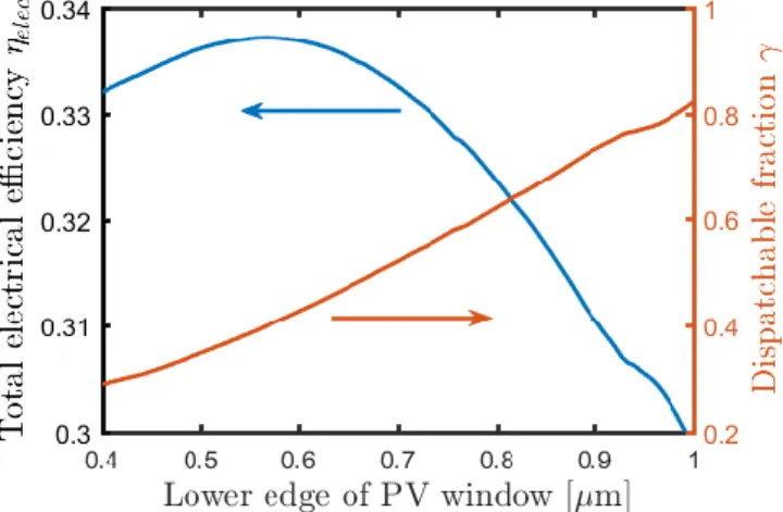
It should be noted that the results shown in Figure 2 are the result of choosing the fraction of the solar spectrum directed to the PV cell in order to maximize total electrical efficiency. At any operating point, dispatachability can be increased at the cost of efficiency by reducing . An example of this is shown in Fig. 3 for a HEATS receiver operating at 700 K using a PV cell with a bandgap of 1.1 µm (corresponding to silicon). At this operating point, the maximum efficiency is 33.7%, which occurs with a dispatchability fraction of 40.2%. The for this maximum efficiency point is 0.52, which corresponds to photons with wavelengths from 0.57 to 1.1 µm being directed to the PV cell. If this window is reduced and more of the solar spectrum is absorbed as thermal energy, the dispatchable fraction increases. For example, if photons with wavelengths from 0.8 to 1.1 µm are directed to the PV cell and the rest are absorbed as thermal energy, which corresponds to an of 0.24, the dispatchable fraction is increased to 62.2%, but efficiency drops to 32.4%. Thus, depending on the value of dispatchability, one might choose different values than those used to generate values in Fig. 2.
Figure 3 Total electrical efficiency (left axis, blue curve) and dispatchable fraction (right axis, red curve) for HEATS receiver as a function of PV window for a 1.1 µm bandgap cell and operating temperature of 700 K. Portion of solar spectrum directed to the PV cell goes from the edge of the PV window to the band gap, so larger PV window edge values correspond to smaller . Efficiency peaks for a PV window edge
around 0.57 µm, after which efficiency can be sacrificed to increase dispatchability fraction.
Modeling receiver performance with measured sub-component properties
In this section, we employ a more sophisticated model for determining HEATS receiver performance which uses measured sub-component properties rather than prescribing simplified metrics. Details on the SSLP and aerogel measurements are provided in Supplemental Information section S2 and some measurements are also published in separate papers,45,46 including spectrally resolved radiative properties and temperature dependent aerogel effective thermal conductivity, which are important to the following modeling and results. The best measured SSLP coatings to date have shown a solar weighted reflectance of 89% in the PV
band (725 - 1100 nm), and a solar weighted reflectance of 25% in the rest of the solar spectrum.45 Transparent silica aerogels with a solar weighted transmittance as high as 96% through a 9.5 mm thick sample have been demonstrated while achieving an effective thermal conductivity of 0.055 W/m/K between 400 °C and 50 °C for the same sample thickness.46,47 For the HEATS receiver, electricity generated by the PV cell and thermal energy collected by the SSLP depend on the temperature distribution and spectral radiation distribution in the receiver, which are coupled. We model the temperature and radiation distribution in the aerogel portions of the receiver by using the equation of radiative transfer (ERT) coupled to the heat equation. The ERT describes the change in radiation intensity for a particular wavelength through a participating medium (in this case aerogel),48 while the heat equation describes the temperature distribution in a solid. Details on how the temperature and radiation distributions are calculated through the HEATS receiver, as well as details on the particular receiver parameters used, are provided in Supplemental Information section S3. Properties used in this model are summarized in Table 2. It should be noted that many of these parameters are wavelength and temperature dependent, in which case the tabulated values are not direct inputs to the model, but averaged values calculated from the modeled conditions. Further details and justifications for these values are discussed in Supplemental Information section S3.
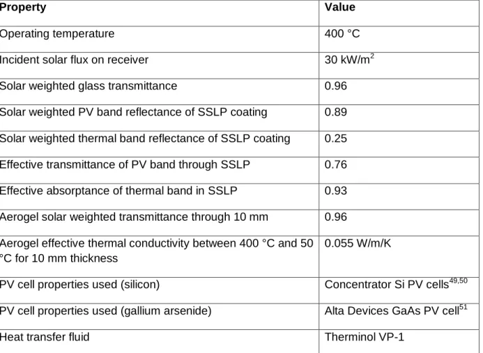
Table 2 Fixed HEATS receiver properties used in sophisticated model
Property Value
Operating temperature 400 °C
Incident solar flux on receiver 30 kW/m2
Solar weighted glass transmittance 0.96
Solar weighted PV band reflectance of SSLP coating 0.89 Solar weighted thermal band reflectance of SSLP coating 0.25 Effective transmittance of PV band through SSLP 0.76 Effective absorptance of thermal band in SSLP 0.93 Aerogel solar weighted transmittance through 10 mm 0.96 Aerogel effective thermal conductivity between 400 °C and 50 °C for 10 mm thickness
0.055 W/m/K
PV cell properties used (silicon) Concentrator Si PV cells49,50 PV cell properties used (gallium arsenide) Alta Devices GaAs PV cell51
Heat engine cold-side reservoir 37 °C
Ambient temperature 25 °C
Effective convection coefficient of heat sink 300 W/m2/K
In order to establish the feasibility of the concept and demonstrate different sub-components working in tandem, we built a small "prototype" HEATS receiver, shown in Fig. 4a. This small prototype consists of two metal fins with spectrally selective coatings aligned at a 45 ° angle to incident light (so that they form a spectrally selective light pipe) with a layer of transparent aerogel on each side. The prototype aerogel layers are approximately 3 mm thick, which is thinner than would be used in a full-scale receiver, because they were the best transparent aerogel samples on hand when the prototype was fabricated. The effective transmittance of the prototype HEATS receiver was measured using a Cary 5000 UV-Vis-NIR spectrophotometer for wavelengths between 0.28 - 2.5 μm, shown in Fig. 4b (solid red curve). Figure 4b also shows the aerogel transmittance values and SSLP coating reflectance values (solid blue curves) from the best demonstrated sub-components to date, which are described in detail in Supplemental Information section S2. The HEATS model solves the equation of radiative transfer for discrete wavelength bands, assuming constant properties within each band. These solar-weighted, band averaged values are also shown in Fig. 4b (dash-dotted curves) for the measured prototype as well as the values that would correspond to the modeled properties (accounting for the thinner aerogel layers). There is good agreement between the measured and modeled effective transmittance, indicating that the aerogel and spectrally selective light pipe work together as expected and providing some evidence towards the accuracy of the modeled results. The measured effective transmittance of the prototype is a bit higher than the modeled transmittance (10 - 15% absolute) for wavelengths shorter than 0.45 μm and longer than 2 μm, however this disparity would not have a large effect on the results, as those wavelengths represent the tails of the solar spectrum.
Figure 4 a) Photograph of the prototype receiver, with labels indicating the location of the fins with spectrally selective coatings and the aerogel layers. Red arrows indicate the path that light takes through the receiver. b) Sub-component properties: aerogel transmittance and SSLP coating reflectance (solid
blue curves), measured effective transmittance of HEATS prototype (solid red curve), and solar-weighted band averaged values used in the model (blue dash-dotted curve) and from the measured prototype (red dash-dotted curve).
Using the best measured performance to date of subcomponents in the HEATS receiver with a silicon PV cell leads to a total electrical efficiency of 26.8% and a dispatchability of 81%. This is notable as the predicted efficiency is higher than if the HEATS receiver was replaced with a PV only or thermal only receiver, corresponding to efficiencies of about 23.5% and 25.2% respectively. It should be noted that the PV efficiency reported here is lower than values given in the reference due to the high cell operating temperature in the PV only configuration. With the same passive cooling used in the HEATS receiver, a PV only configuration leads to cell temperatures greater than 70 °C, while the PV cell remains below 50 °C when integrated into the HEATS receiver. The hybrid receiver achieves this improved efficiency while still preserving high dispatchability, as the majority of the generated electricity comes from thermal energy. Performance can be improved by using a GaAs PV cell rather than silicon, as the higher band gap allows relevant photons to be converted to electricity more efficiently. In the GaAs configuration, we assume that demonstrated SSLP properties could be maintained while shifting the PV window to a more appropriate range (550 – 850 nm). With GaAs, the HEATS receiver achieves a total electrical efficiency of 28.5% with a dispatchability of 76% (a GaAs PV cell in place of the hybrid receiver would achieve 27.8% efficiency).
The potential performance of the HEATS receiver can further be explored as a function of subcomponent properties. Figure 5 shows total electrical efficiency and dispatchability contour plots of the HEATS receiver as a function of the SSLP fin coatings, with the solar weighted reflectance of the PV band varying between 85% and 97%, and the solar weighted reflectance of the thermal band varying between 10% and 28%. Figure 5a shows that a modest increase in efficiency can be achieved, on the order of tenths of a percent in absolute efficiency, if the SSLP coatings can be improved to reflect more of the PV band and less of the thermal band when a Si PV cell is used. Efficiency is more sensitive to the thermal band reflectance than the PV band reflectance, suggesting that improving the thermal band should be a higher priority. This is reinforced by the effect of SSLP performance on dispatchability, shown in Fig. 5b. Improving the PV reflectance band improves efficiency, but it decreases dispatchability as it leads to less incident solar radiation being absorbed as thermal energy. Subfigures 5c and 5d show the efficiency and dispatchability, respectively, of a HEATS receiver that uses a GaAs PV cell, and show similar trends to the Si HEATS receiver. The most notable difference is that efficiency in the GaAs case is about equally sensitive to the thermal and PV band reflectances. The GaAs HEATS receiver is more sensitive to the PV band reflectance because GaAs has a higher spectral efficiency in the range of photons being directed to it, so there is a larger benefit from converting those photons to electricity at the PV cell rather than thermal energy at the SSLP.
Figure 5 Contour plots showing HEATS receiver performance with varying SSLP coating properties. Blue open circles mark values obtained from the best measured SSLP properties to date. a) Electrical efficiency (%) for HEATS receiver with Si PV cell; b) dispatchability (%) for HEATS receiver with Si PV cell; c) electric efficiency (%) for HEATS receiver with GaAs PV cell; d) dispatchability (%) for HEATS receiver with GaAs PV cell.
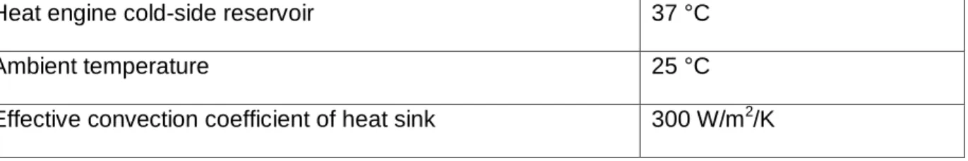
Modifying aerogel transmittance and thermal conductivity will also impact HEATS receiver performance. Figure 6 shows the effect of varying aerogel solar weighted transmittance and thermal conductivity on the HEATS receiver total electrical efficiency for both the Si and GaAs PV cell configurations. For results shown here, the solar weighted transmittance is varied by scaling the extinction coefficient for wavelengths shorter than 2.5 µm, while thermal conductivity is varied by scaling the extinction coefficient for wavelengths longer than 2.5 µm. The values for both solar weighted transmittance and effective thermal conductivity correspond to a 10 mm thick sample. As shown in Fig. 6, there is room for improvement to efficiency of about 1% absolute if aerogel properties can be further improved. Efficiency is sensitive to both transmittance and thermal conductivity, so improving either would lead to valuable increases in efficiency. Dispatchability is not a strong function of aerogel properties, varying less than 5% over the range of interest plotted in Fig. 6, and as such has not been included here.
Figure 6 Contour plots of HEATS receiver electric efficiency [%] as a function of aerogel solar weighted transmittance through 10 mm and effective thermal conductivity through 10 mm for a a) Si HEATS receiver and a b) GaAs HEATS receiver. The open circles mark the best measured aerogel properties to date.
In most solar thermal systems, higher concentration ratios lead to higher efficiency, and the results reported here are for the case of a geometric concentration ratio of 35×. Lower concentrations also lead to worse performance in this case, however a concentration of 20× leads to only a moderate drop in total electrical efficiency of about 1% (absolute). Efficiency is more sensitive to lowering concentration for values less than 20×. Increasing the concentration ratio above 35× leads to only minor gains, as without active cooling of the PV cell the elevated cell temperatures begin to degrade PV performance. Thus the chosen value of 35× strikes an effective balance: it is high enough to allow efficient thermal operation without overheating the PV cell.
While the efficiency predicted in the HEATS system using the best measured values to date is not ground breaking in its own right, the receiver is still shown to be a capable platform, as it achieves higher efficiency than a PV only or thermal only receiver used in its place. Modest gains in efficiency could be achieved by improving the subcomponents of the HEATS receiver, but there is more room for improvement in the HEATS receiver as progress is made in PV and solar thermal technologies. Efficiency could be pushed higher if there were heat transfer fluids compatible with line focus solar thermal systems that were stable above 400 °C.13 Additionally, the HEATS receiver could achieve higher efficiency if there were production ready PV cells better suited for spectral splitting. Production silicon cells typically have a peak spectral conversion efficiency around 40% - not substantially higher than the efficiency at which heat at 400 °C can be converted to electricity.27 Gallium arsenide cells could provide a better option if the SSLP coatings can be demonstrated with reflectance bands appropriate to GaAs.
Concluding remarks
The proposed HEATS receiver efficiently converts solar radiation to both thermal energy and electricity through use of a spectrally selective light pipe and transparent thermally insulating aerogel layers. An idealized model predicts that 35.2% total electrical efficiency should be
possible by using such an arrangement, with over 40% of the electricity being generated from thermal energy, and therefore dispatchable. When considering measured sub-component properties, modeling indicates that the HEATS receiver can achieve an total electrical efficiency of 26.8% when a Si PV cell is used and 28.5% when a GaAs PV cell is used, with over 75% dispatchability in both cases. Notably, these efficiencies are higher than if the HEATS receiver was replaced with just a PV cell or a purely thermal receiver. Moderate improvement in properties could be achieved if the aerogel and SSLP properties can be improved further, and more significant improvements could be achieved as progress in solar thermal technologies allow operation at higher temperature and production PV cells become available that are more suited for spectral splitting in this application. The HEATS receiver offers a new direction for solar energy that can achieve both high electrical efficiency and high dispatchability.
Acknowledgements
This work was primarily supported by ARPA-E and the Department of Energy under contract DE-AR0000471 (for system conception, aerogel and modelling). We also acknowledge support for the development of spectrally selective surfaces from the S3TEC Center, an Energy Frontier Research Center funded by the Department of Energy, Office of Science, Basic Energy Sciences under Award # DE-FG02-09ER46577 (for selective surface fabrication). We thank Dr. Nenad Miljkovic for early work on the hybrid receiver concept and Dr. Xiaopeng Huang for assistance in developing the aerogel thermal conductivity measurement setup.
Author contributions
Conceptualization, all co-authors; Methodology, L.A.W., K.M., E.S., and J.L.; Software, L.A.W., K.M., E.S., and J.L.; Investigation, L.A.W., E.S., B.B., L.Z., and Y.H.; Resources, E.S., S.Y., B.B., L.Z., and F.C.; Writing – Original Draft, L.A.W.; Writing – Review & Editing, all co-authors; Visualization, L.A.W.; Funding Acquisition, K.M., S.V.B., Z.R., E.N.W., and G.C.; Supervision, S.V.B., Z.R., E.N.W. and G.C.
References
1. Crabtree, G.W., and Lewis, N.S. (2007). Solar energy conversion. Phys. Today 60, 37– 42.
2. REN21 (2016). Renewables 2016 Global Status Report (Paris).
3. Shockley, W., and Queisser, H.J. (1961). Detailed Balance Limit of Efficiency of p-n Junction Solar Cells. J. Appl. Phys. 32, 510.
4. Rühle, S. (2016). Tabulated values of the Shockley–Queisser limit for single junction solar cells. Sol. Energy 130, 139–147.
5. Dunn, B., Kamath, H., and Tarascon, J.-M. (2011). Electrical Energy Storage for the Grid: A Battery of Choices. Science (80-. ). 334, 928–935.
6. Denholm, P., and Mehos, M. (2011). Enabling Greater Penetration of Solar Power via the Use of CSP with Thermal Energy Storage.
7. Jorgenson, J., Denholm, P., and Mehos, M. (2014). Estimating the Value of Utility-Scale Solar Technologies in California Under a 40% Renewable Portfolio Standard (Golden, CO (United States)).
8. Weinstein, L.A., Loomis, J., Bhatia, B., Bierman, D.M., Wang, E.N., and Chen, G. (2015). Concentrating Solar Power. Chem. Rev. 115, 12797–12838.
9. Bauer, T., Steinmann, W.-D., Laing, D., and Tamme, R. (2012). THERMAL ENERGY STORAGE MATERIALS AND SYSTEMS. Annu. Rev. Heat Transf. 15, 131–177.
10. IBRAHIM, H., ILINCA, A., and PERRON, J. (2008). Energy storage systems— Characteristics and comparisons. Renew. Sustain. Energy Rev. 12, 1221–1250.
11. Hernández-Moro, J., and Martínez-Duart, J.M. (2013). Analytical model for solar PV and CSP electricity costs: Present LCOE values and their future evolution. Renew. Sustain. Energy Rev. 20, 119–132.
12. Branz, H.M., Regan, W., Gerst, K.J., Borak, J.B., and Santori, E.A. (2015). Hybrid solar converters for maximum exergy and inexpensive dispatchable electricity. Energy Environ. Sci. 8, 3083–3091.
13. Bermel, P., Yazawa, K., Gray, J.L., Xu, X., and Shakouri, A. (2016). Hybrid strategies and technologies for full spectrum solar conversion. Energy Environ. Sci. 3, 2123.
14. Imenes, A.G., Buie, D., and McKenzie, D. (2006). The design of broadband, wide-angle interference filters for solar concentrating systems. Sol. Energy Mater. Sol. Cells 90, 1579–1606.
15. Crisostomo, F., Taylor, R.A., Surjadi, D., Mojiri, A., Rosengarten, G., and Hawkes, E.R. (2015). Spectral splitting strategy and optical model for the development of a concentrating hybrid PV/T collector. Appl. Energy 141, 238–246.
16. Otanicar, T.P., Theisen, S., Norman, T., Tyagi, H., and Taylor, R.A. (2015). Envisioning advanced solar electricity generation: Parametric studies of CPV/T systems with spectral filtering and high temperature PV. Appl. Energy 140, 224–233.
17. Luque, A., and art , A. (1999). Limiting efficiency of coupled thermal and photovoltaic converters. Sol. Energy Mater. Sol. Cells 58, 147–165.
18. Vorobiev, Y., González-Hernández, J., Vorobiev, P., and Bulat, L. (2006). Thermal-photovoltaic solar hybrid system for efficient solar energy conversion. Sol. Energy 80, 170–176.
19. Sharaf, O.Z., and Orhan, M.F. (2015). Concentrated photovoltaic thermal (CPVT) solar collector systems: Part I – Fundamentals, design considerations and current technologies. Renew. Sustain. Energy Rev. 50, 1500–1565.
20. Mojiri, A., Taylor, R., Thomsen, E., and Rosengarten, G. (2013). Spectral beam splitting for efficient conversion of solar energy—A review. Renew. Sustain. Energy Rev. 28, 654– 663.
21. McCambridge, J.D., Steiner, M.A., Unger, B.L., Emery, K.A., Christensen, E.L., Wanlass, M.W., Gray, A.L., Takacs, L., Buelow, R., McCollum, T.A., et al. (2011). Compact spectrum splitting photovoltaic module with high efficiency. Prog. Photovoltaics Res.
Appl. 19, 352–360.
22. Zhao, Y., Sheng, M.-Y., Zhou, W.-X., Shen, Y., Hu, E.-T., Chen, J.-B., Xu, M., Zheng, Y.-X., Lee, Y.-P., Lynch, D.W., et al. (2012). A solar photovoltaic system with ideal efficiency close to the theoretical limit. Opt. Express 20, A28.
23. Eisler, C.N., Kosten, E.D., Warmann, E.C., and Atwater, H.A. (2013). Polyhedral specular reflector design for ultra high spectrum splitting solar module efficiencies (>50%). In, A. P. Plesniak, ed. (International Society for Optics and Photonics), p. 88210B.
24. Lloyd, J. V., Kosten, E.D., Warmann, E.C., Flowers, C.A., and Atwater, H.A. (2014). Ray trace optimization of a light trapping filtered concentrator for spectrum splitting photovoltaics. In 2014 IEEE 40th Photovoltaic Specialist Conference (PVSC) (IEEE), pp. 2249–2252.
25. Jiang, S., Hu, P., Mo, S., and Chen, Z. (2010). Optical modeling for a two-stage parabolic trough concentrating photovoltaic/thermal system using spectral beam splitting technology. Sol. Energy Mater. Sol. Cells 94, 1686–1696.
26. Saroha, S., Mittal, T., Modi, P.J., Bhalla, V., Khullar, V., Tyagi, H., Taylor, R.A., and Otanicar, T.P. (2015). Theoretical Analysis and Testing of Nanofluids-Based Solar Photovoltaic/Thermal Hybrid Collector. J. Heat Transfer 137, 91015.
27. Yu, Z.J., Fisher, K.C., Wheelwright, B.M., Angel, R.P., and Holman, Z.C. (2015). PVMirror: A New Concept for Tandem Solar Cells and Hybrid Solar Converters. IEEE J. Photovoltaics 5, 1791–1799.
28. Cygan, D., Abbasi, H., Kozlov, A., Pondo, J., Winston, R., Widyolar, B., Jiang, L., Abdelhamid, M., Kirk, A.P., Drees, M., et al. (2016). Full Spectrum Solar System: Hybrid Concentrated Photovoltaic/Concentrated Solar Power (CPV-CSP). MRS Adv., 1–6. 29. Landis, G., Merritt, D., Raffaelle, R., and Scheiman, D. (2005). High-temperature solar
cell development.
30. Singh, P., and Ravindra, N.M. (2012). Temperature dependence of solar cell performance—an analysis. Sol. Energy Mater. Sol. Cells 101, 36–45.
31. Kribus, A., Kaftori, D., Mittelman, G., Hirshfeld, A., Flitsanov, Y., and Dayan, A. (2006). A miniature concentrating photovoltaic and thermal system. Energy Convers. Manag. 47, 3582–3590.
32. Chow, T.T. (2010). A review on photovoltaic/thermal hybrid solar technology. Appl. Energy 87, 365–379.
33. Paredes, S., Burg, B.R., Ruch, P., Lortscher, E., Malnati, F., Cucinelli, M., Bonfrate, D., Mocker, A., Bernard, A., Ambrosetti, G., et al. (2015). Receiver-module-integrated thermal management of high-concentration photovoltaic thermal systems. In 2015 IEEE 42nd Photovoltaic Specialist Conference (PVSC) (IEEE), pp. 1–6.
34. Wang, N., Han, L., He, H., Park, N.-H., Koumoto, K., Nazeeruddin, M.K., Grätzel, M., Wang, P., Zakeeruddin, S.M., and Grätzel, M. (2011). A novel high-performance photovoltaic–thermoelectric hybrid device. Energy Environ. Sci. 4, 3676.
Solar Absorbers. In Annual Review of Heat Transfer Vol. 15 (Begell House), pp. 231– 254.
36. Bedford, R.E., and Ma, C.K. (1974). Emissivities of diffuse cavities: Isothermal and nonisothermal cones and cylinders. J. Opt. Soc. Am. 64, 339.
37. Soleimani Dorcheh, A., and Abbasi, M.H. (2008). Silica aerogel; synthesis, properties and characterization. J. Mater. Process. Technol. 199, 10–26.
38. Tillotson, T.M., and Hrubesh, L.W. (1992). Transparent ultralow-density silica aerogels prepared by a two-step sol-gel process. J. Non. Cryst. Solids 145, 44–50.
39. Alaoui, A.H., Woignier, T., Scherer, G.W., and Phalippou, J. (2008). Comparison between flexural and uniaxial compression tests to measure the elastic modulus of silica aerogel. J. Non. Cryst. Solids 354, 4556–4561.
40. Bejan, A. (1996). Entropy generation minimization: The new thermodynamics of finite-size devices and finite-time processes. J. Appl. Phys. 79, 1191.
41. Mehos, M., Turchi, C., Jorgenson, J., Denholm, P., Ho, C., and Armijo, K. (2016). On the Path to SunShot. Advancing Concentrating Solar Power Technology, Performance, and Dispatchability (Golden, CO (United States)).
42. Miller, O.D., Yablonovitch, E., and Kurtz, S.R. (2012). Strong Internal and External Luminescence as Solar Cells Approach the Shockley–Queisser Limit. IEEE J. Photovoltaics 2, 303–311.
43. Green, M.A. (2012). Radiative efficiency of state-of-the-art photovoltaic cells. Prog. Photovoltaics Res. Appl. 20, 472–476.
44. Yu, Z. (Jason), Leilaeioun, M., and Holman, Z. (2016). Selecting tandem partners for silicon solar cells. Nat. Energy 1, 16137.
45. Cao, F., Huang, Y., Tang, L., Sun, T., Boriskina, S. V., Chen, G., and Ren, Z. (2016). Toward a High-Efficient Utilization of Solar Radiation by Quad-Band Solar Spectral Splitting. Adv. Mater. 28, 10659–10663.
46. Strobach, E., Bhatia, B., Yang, S., Zhao, L., and Wang, E.N. (2017). High temperature annealing for structural optimization of silica aerogels in solar thermal applications. J. Non. Cryst. Solids 462, 72–77.
47. Bhatia, B., Yang, S., Zhao, L., Strobach, E., and Wang, E.N. Silica Aerogels for Concentrating Solar Power Applications. Prep.
48. Modest, M.F. (2013). Radiative Heat Transfer Third. (Academic Press).
49. Sinton, R.A., Young Kwark, Gan, J.Y., and Swanson, R.M. (1986). 27.5-percent silicon concentrator solar cells. IEEE Electron Device Lett. 7, 567–569.
50. Slade, A., and Garboushian, V. (2005). 27.6% efficient silicon concentrator solar cells for mass production. Tech. Dig. 15th Int.
51. Kayes, B.M., Nie, H., Twist, R., Spruytte, S.G., Reinhardt, F., Kizilyalli, I.C., and Higashi, G.S. (2011). 27.6% Conversion efficiency, a new record for single-junction solar cells
under 1 sun illumination. In 2011 37th IEEE Photovoltaic Specialists Conference (IEEE), pp. 000004–000008.
Supplemental Information
S1 – Details of idealized model for HEATS receiver performance
The idealized model for calculating HEATS receiver performance assumes a PV cell with an external radiative efficiency of 1%, ignores edge effects in the receiver (i.e., transport through the layers is treated as one dimensional), and thermal properties of the receiver do not vary with temperature. For this model, properties of the HEATS receiver subcomponents, such as aerogel transmittance, are prescribed directly and treated as constant within each spectral band. This model is shown schematically in Fig. S1, showing how properties of the receiver subcomponents relate to Eqs. (S1) and (S2) for calculating generated electricity and collected thermal energy.
Figure S1 Diagram illustrating idealized model. Arrows show energy flows through receiver for different bands of
solar spectrum, with collected thermal energy on right, generated electricity on bottom, and lost energy terminating at black crosses. The layers of the HEATS receiver are labeled on the left, along with their corresponding terms in Eqs. (3) and (4). The terms for all layers except for the spectrally selective light pipe (SSLP) correspond to the portion of energy that is retained through that layer. The SSLP efficiency corresponds to the portion of energy that is successful absorbed as thermal energy (for the thermal bands) or transmitted towards the PV cell (for the PV band).
In this model the electricity generated from the PV cell comes from two sources: solar radiation in the PV band and solar radiation in the thermal bands that leaks through the SSLP. The equation for this generated electricity is:
(S1)
where is glass cover transmittance, is transmittance of the portion of the solar spectrum being directed to the PV cell through one aerogel layer (this term is squared as it is assumed in this model that the two aerogel layers have equal transmittance), is the fraction of the solar spectrum directed to the PV cell, is PV cell efficiency for the spectrum intended to be converted by PV, is effective transmittance of the SSLP in the part of the spectrum being directed towards the PV cell,
is transmittance of the portion of the solar spectrum to be absorbed as thermal energy through one aerogel layer, is PV cell efficiency for the spectrum intended to be absorbed as thermal
energy, and is effective absorptance of the SSLP in the portion of the solar spectrum to be absorbed as thermal energy. The first term inside the square brackets corresponds to electricity generated from the portion of the solar spectrum intended to be sent to the PV cell, while the second term corresponds to electricity generated from the portion of the spectrum intended to be collected as thermal energy.
The thermal energy collected by the receiver consists of two sources: solar radiation in the thermal bands and solar radiation in the PV band that is inadvertently absorbed by the SSLP. The thermal energy collected by the receiver is given by the sum of these two sources minus thermal losses to the ambient environment:
(S2)
where is effective heat transfer coefficient of one aerogel layer, is the Stefan-Boltzmann constant, and is the blackbody emissive fraction function.1 The first term in this equation corresponds to solar radiation absorbed by the light pipe. The first term inside the square brackets corresponds to thermal energy from solar radiation in the thermal bands, as is the effective light pipe absorptance for the thermal bands. The second term in the brackets corresponds to thermal energy from solar radiation in the PV band absorbed inadvertently, as is the effective light pipe absorptance for the PV band. The last two terms correspond to thermal losses from the light pipe (operating at ) through the aerogel layers on both sides. The first thermal loss term (with ) includes conduction through the aerogel and radiation through the aerogel for wavelengths longer than 2 μm. The second thermal loss term considers the radiation losses through the aerogel at wavelengths shorter than 2 μm (for which wavelengths the aerogel is assumed to be completely transparent), which are required for the aerogel to have a high solar weighted transmittance of 95%.
In this model, , the glass and aerogel transmittances, the optical properties of the SSLP, and the heat transfer coefficient of the aerogel are given as inputs. For the results reported, we have used = 30 kW/m2, a typical value for line focus solar thermal systems, and = 0.96, a solar weighted glass transmittance which is achieved in commercial systems.2,3 Additionally, for the light pipe we use 0.95, and for the aerogel we use 0.97, and = 3 W/m2/K. For the purpose of radiative thermal losses, the aerogel is considered to be transparent for wavelengths shorter than 2 μm. These values were chosen because they represent high performing sub-components that should be possible with further development. Coatings for the SSLP could follow a similar trajectory to traditional solar absorber coatings, which have achieved spectral transitions in absorption from above 95% to below 5%.4 Silica aerogels have been reported with solar weighted transmittance values above 95% for 1 cm thick samples,5 and doped silica aerogels have been reported with thermal conductivities below 0.03 W/m/K (corresponding to an effective heat transfer coefficient of 3 W/m2/K for a 1 cm thick sample) at elevated temperatures.6 Further efforts could feasibly achieve both these transmittance and thermal conductivity values in a silica aerogel.
S2 - Measured properties of HEATS sub-components
To get a more accurate estimate for the performance that could be achieved with a HEATS receiver today, measured component properties should be used. While the SSLP and transparent aerogel are not currently used in the solar thermal industry, transparent aerogels and SSLP coatings have been fabricated, characterized and reported in scientific literature.7–9 After reviewing the demonstrated properties of these sub-components, a more sophisticated model can be used to predict the performance of a HEATS receiver that should be achievable at present. While the optimistic results from the simple model show great potential for the HEATS receiver, using measured properties is an important first step to proving near-term viability of the HEATS receiver.
S2.1 - Spectrally Selective Light Pipe (SSLP) coating
The SSLP coatings should reflect photons converted most efficiently by PV while absorbing the rest of the solar spectrum. The physical design of the SSLP is such that reflected photons will be directed to the PV cell. To more precisely understand the ideal spectral properties of the SSLP coating, it is helpful to first look at traditional solar thermal coatings. A traditional spectrally selective absorber has high absorptance in the solar spectrum, but high reflectance (and therefore low emittance) at longer wavelengths. An absorber with these properties can effectively absorb solar radiation, but has minimal radiative losses. The ideal SSLP coating is similar, but has a high reflectance band in the middle of the solar spectrum in order to direct photons which are converted most efficiently by PV to the PV cell (the wavelength band we used to maximize total electrical efficiency with real silicon PV cells was 725 – 1100 nm).10 This leads to four distinct bands in the spectral reflectance profile: high reflectance in the PV band and for mid to far infrared wavelengths, with high absorptance in solar wavelengths outside the PV band, as shown in Fig. S2a. For the HEATS receiver, having high reflectance at long wavelengths may not be critical, as the thermal insulator should block thermal losses, however having high reflectance in this wavelength range will still reduce thermal losses, even if only by a small amount.
Figure S2. Performance of a fabricated SSLP coating from Cao, et al.7 a) Spectral reflectance of fabricated SSLP coating for various angles of incidence. The coating is designed to reflect photons converted efficiently by silicon PV (725 – 1100 nm, the “PV band”), absorb the rest of the solar spectrum, and have low emittance at longer wavelengths b) AM1.5D solar-weighted reflectance within the PV band (blue markers) and in the rest of the solar spectrum (red markers) as a function of incidence angle
In practice, these spectral properties can be achieved by depositing a thin-film multi-layer stack (thereby forming an interference filter)11 on top of a traditional cermet absorber.7 The reflection band can be tuned by changing the thicknesses of alternating layers of high and low index of refraction materials. Details of the quad-band coatings have been reported by some of this paper’s co-authors.7 Using a SiO2/TiOx filter deposited on a W-Ni-SiO2 cermet spectrally selective absorber achieved the properties
shown in Fig. S2. The AM1.5D solar-weighted reflectance within the PV band is about 89%, although it is slightly lower at larger incidence angles, while the solar-weighted reflectance outside the PV band is about 25%.
S2.2 - Transparent aerogel
The transparent insulator should allow solar radiation to pass through unimpeded, while also insulating the SSLP to minimize thermal losses. We propose silica aerogel as the transparent insulator material, which is an extremely low density nanoporous network of silica particles which can be fabricated through a simple sol-gel process.12,13 The ideal radiative properties of the aerogel are simpler than the SSLP, with only two bands: the aerogel should be transparent in the solar spectrum and opaque at longer wavelengths to block thermal radiation losses. The aerogel should also insulate against conductive and convective thermal losses.
In terms of radiative properties, significant work has been done to increase the solar and visible transmittance of silica aerogels. Structurally, the key to achieving high visible transmittance is small, uniform pores. Scattering is the dominant extinction mechanism in aerogels at visible wavelengths, and the observed behavior is characteristic of Rayleigh scattering, which increases drastically with increased scatterer size (in this case, the aerogel pore).14 Transmittance has been controlled by changing the pH of the solution in the sol-gel process, using a two-step sol-gel process, heat treatment, and alternative drying techniques.5,15–18 Absorption is the dominant extinction mechanism for longer solar wavelengths, however those wavelengths do not contribute as significantly to losses in solar-weighted transmission due to absorption peaks being aligned with dips in the AM1.5 solar spectrum (see Fig. S3a). As such, reducing absorption is not critical to achieving high aerogel transmittance.
Figure S3. Performance of fabricated transparent aerogel samples from Bhatia, et al.9 a) Spectral transmittance for a 9.5 mm thick aerogel sample, along with solar spectral irradiance and blackbody irradiance spectrum at 400 °C. Aerogel is highly transparent in the solar spectrum, but is absorbing in the blackbody spectrum at 400 °C. Solar weighted transmittance of this sample is 96%. b) Absorption (red) and scattering (blue) coefficients inferred from measurements for fabricated aerogel sample. Scattering dominates for short solar wavelengths, while absorption dominates for longer wavelengths. c) Measured (blue open markers) and modeled (dashed black curve) thermal conductivity of a transparent aerogel sample in vacuum. Error bars for measured results come primarily from uncertainty in aerogel sample thickness.
Aerogel samples with a solar-weighted transmittance of 96% through 9.5 mm designed for solar thermal applications have recently been reported by some of this paper’s co-authors.8,9 The spectral transmittance for a high performing sample is plotted in Fig. S3a, along with the solar spectrum and the blackbody spectrum for a surface at 400 °C. While the aerogel has high transmittance in the solar spectrum, it blocks radiation at the longer wavelengths characteristic of radiative heat transfer for solar thermal receivers operating near 400 °C. By measuring both the transmittance and reflectance of the sample, one can also infer the intrinsic radiative properties (scattering and absorption coefficients) of the aerogel,14 which are plotted in Fig. S3b. Scattering coefficient values are fit to a Rayleigh scattering model based on measured values, while absorption coefficient values are reported based on directly measured values.
Thermal conductivity in the aerogel has three components: conduction through the silica network, conduction through the air, and radiation.19 Radiation has the most significant impact at high temperatures, and as previously mentioned, high absorptance at long photon wavelengths can reduce the radiative component of thermal conductivity.20 Achieving low thermal conductivity is therefore also closely tied to the radiative properties of the aerogel. Increasing infrared absorption in the aerogel can be accomplished by fabricating denser aerogels or including adsorbed species in the aerogel (e.g., water).21
Thermal conductivities of the reported aerogel samples were measured using a heater bridge setup, where a temperature difference across the sample is maintained through power input to a heater.9 The temperature difference is modulated and the corresponding change in required heater input power is measured. Measured thermal conductivity is given by the following equation, which assumes one-dimensional thermal transport through the sample:22
(S3)
where is sample thickness, is the sample cross sectional area, is change in heater input power, and is change in temperature difference across the sample. The measured thermal conductivity value can also be compared to a modeled value which uses the infrared absorption coefficients as input (the modeling method is described in detail in the following section) to verify the results. Thermal conductivity is strongly temperature dependent: measured effective thermal conductivities range from 0.02 to 0.07 W/m/K in vacuum for operating temperatures of 200 °C to 400 °C, with strong agreement between measured and modeled values (see Fig. S3c).
S3 - Details on sophisticated model for HEATS receiver performance
In this model, which uses measured aerogel and SSLP surface properties rather than simple prescribed properties, total electrical efficiency is also determined from the thermal energy collected from the SSLP and electricity collected from the PV cell. We model the temperature and radiation distribution in the aerogel portions of the receiver by using the equation of radiative transfer (ERT) coupled to the heat equation. The ERT describes the change in radiation intensity for a particular wavelength through a participating medium (in this case aerogel): 1
(S4)
where is radiation intensity in the direction , is the angle between (The direction of interest through the aerogel) and , is the extinction coefficient, is the absorption coefficient, is blackbody radiation intensity for the local aerogel temperature, is the scattering coefficient, and is the scattering phase function (with all of these values corresponding to the wavelength that the ERT is being solved for). More intuitively, the left hand side of the ERT is the change in radiative intensity through the aerogel in the direction , the first term on the right hand side is a decrease in radiative intensity due to absorption and scattering into different directions, the second term is an increase in
intensity due to emission from the aerogel, and the third term is an increase in intensity due to scattering from other directions into the current direction. In practice, some simplifications must be made to the ERT in order to solve for the radiation distribution in the aerogel layers. First, the scattering phase function is assumed to be isotropic.23 Additionally, It is intractable to solve the ERT at every wavelength; instead the relevant spectrum (from about 300 nm as the shortest solar wavelength to about 50 µm as the longest relevant infrared wavelength) is broken into bands, over which the material properties are averaged and treated as constant.20,24 Thus, for radiation within a band , the ERT becomes:
(S5)
where is radiation intensity in the direction within the band , and the other symbols with an subscript similarly denote properties averaged over the band . The blackbody intensity within the band is given by:25
(S6)
where is the index of refraction of the aerogel (taken as the volume weighted average between air and silica, and therefore close to 1), is the Stefan-Boltzmann constant, is the temperature of the aerogel at the position , is a constant equal to 0.01439 m K, and the band spans the wavelengths from to . For each band, the heat flux in the direction of interest is given by:
(S7)
The heat equation describes the temperature distribution in a solid, and for the steady-state case (which we assume for the HEATS receiver) the heat equation is:
(S8)
where is temperature, is volumetric heat generation/absorption in the solid, and is (non-radiative) thermal conductivity of the solid. It should be noted that since the aerogel samples were measured in vacuum conditions, a constant air contribution of 0.01 W/m/K is included in this when modeling the receiver, which operates at ambient pressure.19 More explicitly for an aerogel layer in the HEATS receiver, the heat equation can be written:
(S9)
Thus, in the aerogel portion of the HEATS receiver, the ERT and heat equation are coupled through two terms: the blackbody radiation intensity and volumetric heat generation/absorption . These terms lead to coupling because depends on the local aerogel temperature and volumetric heat generation/absorption comes from the net radiative flux at a point in the aerogel being non-zero (e.g.,


![Figure 6 Contour plots of HEATS receiver electric efficiency [%] as a function of aerogel solar weighted transmittance through 10 mm and effective thermal conductivity through 10 mm for a a) Si HEATS receiver and a b) GaAs HEATS receiver](https://thumb-eu.123doks.com/thumbv2/123doknet/14448680.518219/16.918.114.809.107.391/contour-receiver-electric-efficiency-function-transmittance-effective-conductivity.webp)


