Developing a Contactless Bankcard Fare Engine for Transport for London by
Peter S. C. Lau
B.S. Electrical Engineering and Computer Sciences University of California, Berkeley, 2007
SUBMITTED TO THE DEPARTMENT OF CIVIL AND
ENVIRONMENTAL ENGINEERING IN PARTIAL FULFILLMENT OF THE REQUIREMENTS FOR THE DEGREE OF
MASTER OF SCIENCE IN TRANSPORTATION AT THE
MASSACHUSETTS INSTITUTE OF TECHNOLOGY JUNE 2009
MASSACHUSETTS INSTITUTE OF TECHNOLOGY
JUL
10 2009
LIBRARIES
©2009 Massachusetts Institute of Technology. All rights reserved.Signature of Author:
Department of Civil and Environmental Engineering May 21, 2009
Certified by:
George Kocur Senior Lecturer of Civil and Environmental Engineering Thesis Supervisor
Certified by:
Nigel H. M. Wilson Professor of Civil and Environmental Engineering Director, Master of Science in Tra rtation
Daniele Veneziano Professor of Civil and Environmental Engineering Chairman, Departmental Committee for Graduate Students Accepted by:
Developing a Contactless Bankcard Fare Engine for Transport for London by
Peter S. C. Lau
Submitted to the Department of Civil and Environmental Engineering on May 21, 2009 in Partial Fulfillment of the Requirements for
the Degree of Master of Science in Transportation
ABSTRACT
This thesis investigates the design of a fare engine which operates within the constraints of using contactless bankcards as a fare instrument, while satisfying the complex current and future fare requirements of Transport for London (TfL). A fare engine is a system which transforms user transactions at fare gates and validators into chargeable fares. Contactless bankcard fare payment differs from current fare smartcard systems by requiring a centralized fare engine.
The proposed fare engine utilizes a data structure which maintains each user's journey history in three successive tiers of linked objects. This structure enables transactions to be correctly sequenced without a guarantee of in-order arrival of gate and validator transactions. A cleanup routine prevents the data structure from growing without bound as journey history accumulates. A dynamic journey linking mechanism allows the effect of inserted transactions to be propagated throughout the data structure and reflected in the affected journeys with near-constant time complexity. This ensures scalability while providing real-time feedback for customer service and payment authorization needs.
A solution is devised for the coupling of arbitrary origin-destination fares with zonal period tickets. The paradigm of automatic ticket selection is introduced, overcoming the limitations of the existing capping algorithm used by TfL. Through the tracking of parallel fare scenarios, passengers are guaranteed a total fare no higher than if they had purchased the optimal period ticket for their usage profile.
With the solutions proposed in this thesis, a contactless bankcard fare engine for TfL appears feasible.
Thesis Supervisor: George Kocur
Acknowledgements
I would like to express my thanks to my advisor, George Kocur, who never failed to provide gems of expertise and timely insight. My appreciation also goes to Professor Nigel Wilson and John
Attanucci for their guidance and advice throughout the course of this degree.
This research is funded by Transport for London as part of its collaboration with MIT. I would like to acknowledge Will Judge and Shashi Verma of TfL for the support they have lent to this project, as well as the staff of Fares and Ticketing - Brian Dobson, Ian Thomley, Behdad Haddadien, Peter Svensson and Andrew Gaitskell for their assistance and feedback.
I want thank all of my colleagues in the MST program for their support and in particular, Michael Frumin and Candace Brakewood for their help in the area of fare payment. I am also grateful to Ginny Siggia, whose hard work has kept this program running smoothly.
Finally I owe the deepest appreciation to my parents and to Sara, who has given me endless encouragement and the strength to see this thesis through to completion from its uncertain beginnings.
Table of Contents
Acknowledgements ... 4
Table of C ontents ... 5
1 Introduction and Background ... 13
1.1 Traditional Electronic Fare Payment Technologies ... ... 13
1.1.1 M agnetic F arecards... 13
1.1.2 Transit Sm artcards ... 14
1.1.3 C om m on C hallenges... ... 15
1.2 Overview of Contactless Bankcards ... 16
1.2.1 Contactless Smartcard as a Financial Instrument ... ... 16
1.2.2 State of the Technology in the US... 16
1.2.3 State of the Technology in UK and Europe ... ... 17
1.2.4 Bankcard Payment Process ... 18
1.3 Direct Fare Payment with Contactless Bankcards... ... 20
1.3.1 Earlier Attempts at Transit-Contactless Bankcard Integration ... ... 20
1.3.2 Benefits of Direct Fare Payment with Contactless Bankcards ... ... 21
1.3.3 Issues and Challenges ... ... ... 22
2 Research Question and Framework ... ... 26
2.1 D efinitions... . ... ... ... ... ... 26
2.1.1 What is a Fare Collection System? ... .. .. . . .. .. . .. .. .. .. .. . . . 26
2.1.2 W hat is a Fare Engine? ... .. .. . . . ... . .. . .. .. .. . .. .. .. .. .. .. . .. .. .. .. .. . .. .. .. .. . .27
2.1.3 Example of a Simple Fare Collection System ... ... 27
2.2 Research Q uestion... ... ... 29
2.3 Investigative Process ... 29
2.4 Developm ent Considerations ... 30
3 Current TfL Fare Structure ... ... 31
3.1 Fare D escription ... ... 3 1 3.1.1 Lateral Consistency ... ... ... 31
3.2 General Fare Structures ... ... ... 32
3.2.2 Fare structure Evolution ... ... ... 33
3.2.2.1 Conceptual Fare Structure ... 33
3.2.2.2 Parameterized Fare Structure ... 34
3.2.2.3 Domain-defined Fare Structure ... 34
3.2.2.4 Initialized Fare Structure ... 35
3.2.3 Applying a Fare Structure.. ... ... ..36
3.2.4 Normalization of Fare Variation... ... ... 36
3.2.5 Fare Structure Implementation ... 37
3.2.6 Limitations of a Matrix Based Fare Structure ... 38
3.3 Organization of a TfL Fare Structure ... 38
3.3.1 Product Spheres ... ... ... 38
3.3.2 H ybrid and B ridging Features ... 39
3.4 Single Products ... ... 39
3.4.1 Tier Definition and Structural Domain ... 40
3.4.1.1 Fare M edium ... ... 42 3.4.1.2 D iscount G roup ... ... 42 3.4.1.3 T im e Band ... ... 42 3.4.2 Charge Code ... ... 43 3.4.2.1 T fL Z ones ... ... ... 44 3.4.2.2 Z onal Pairs... ... ... 44 3.4.2.3 Special C ases ... ... 45
3.4.2.4 Charge Code Lookup... ... ... 46
3.4.2.5 Charge code Optim izations ... ... 47
3.4.2.5.1 Type 1 Optimization ... 47
3.4.2.5.2 Type 2 O ptim ization ... ... 48
3.4.2.6 Charge Code Exam ple ... 48
3.4.2.7 C harge C ode Sum m ary... 5 1 3.4.3 Bus Journeys... ... 51
3.4.4 Matrix Utilization and Treatment of Null Fields ... 52
3.4.5 Example M aster M atrix ... ... 53
3.5 Period Products ... ... ... ... 55
3.5.1 Tier Definition and Structural Argum ents ... ... 55
3 .5.1.1 A pp lication C ontext ... 55
3.5.1.2 D iscount G roups ... ... 57
3.5.1.3 Validity Periods ... 57
3.5.2 C harge C ode ... ... ... ... 59
3.5.3 M atrix Utilization ... ... ... 62
3.6 Interchanges ... ... 63
3.6.1 Out-of-Station Interchange ... ... ... 63
3.6.2 Bus-Rail Interchange ... ... 63
3.6.3 N ational Rail Interchange ... 64
3.7 PAYG Capping ... ... ... 64
3.7.1 Peak and Off-peak Caps ... ... ... 65
3.7.2 Oyster Implementation ... ... ... 66
3.7.3 Running Total Example ... 67
3.7.4 W orked Exam ple ... 68
3.7.5 Capping Lim itations ... ... ... 70
3.7.5.1 Zonal O verextension ... 71
3.7.5.2 Cross-band Zonal Interference ... 72
3.7.5.3 Non-contiguous Zonal Overextension ... ... 73
3.7.5.4 Capping with Pre-existing Tickets ... ... 74
3.7.6 Capping and Buses ... ... ... 75
3.8 Other Services ... 75
3.9 M otivations for a Fare Structure ... 77
3.9.1 M otivation vis a vis Oyster... 77
3.9.2 The User Experience Motivation ... ... 78
3.9.3 The Next Generation Fare Engine Motivation ... 79
4 Fare Engine Requirem ents ... 80
4.1 Travel Services... ... ... 80 4.2 Product Spheres... 81 4 .3 F are M edia ... ... 8 1 4.4 User Identification... ... 81 4.5 Modes Supported ... 81 4 .6 Single Products ... ... 82 4.6.1 Fare C alculation... ... 82 4.6.2 Tim e Bands... ... . . . 83 4.6.3 Discount Groups ... ... ... 84 4.7 Journey Properties ... ... 85
4.8 Journey Linking ... ... ... ... 86
4.8.1 Definition of a Linked Journey ... ... 86
4.8.2 Journey Segments ... 87
4.8.3 Journey Linking Criteria... 87
4.8.4 Out-of-station interchange (OSI)... 88
4.8.5 Intermediate Validation ... 89 4.8.6 Cross-mode Interchange ... 90 4.9 Period Products ... 92 4.9.1 Best V alue ... ... ... 92 4.9.2 Modes ... ... 93 4 .9 .3 T im e ban ds ... ... 93 4.9.4 D iscount G roups... ... 94 4.9.5 Zonal Validity ... ... 94 4.10 O ther Services... ... ... ... ... .94
5 TfL Future Ticketing Architecture ... 96
5.1 F inancial E ntities... ... ... 97 5.1.1 C ontactless B ankcard ... ... 97 5.1.2 Merchant Acquirer... 98 5.1.3 C ard Issuer ... 98 5.2 Customer Interfaces ... 98 5.2 .1 Point of service ... ... 98 5.2.2 Website/Kiosk ... 99 5.3 Internal Subsystem s ... ... ... ... 99 5.3.1 D evice M anager... ... ... ... ... . 99 5.3.2 R isk M anager... ... 100 5.3.3 A ccount M anager ... ... 100 5.3.4 Billing Engine... ... ... 101 5.3.5 Fare Engine... ... ... 102
6 Fare Engine Design ... 103
6 .1 D esign C riteria ... ... 103
6.2 Fare Engine O rganization ... 103
6.3 Fare Engine D ata Flow s ... ... 104 6 .3 .1 T ap ... ... 10 5
6.3.2 LinkedJourney ... 107
6.3.2.1 JourneySegm ent ... 107
6 .3 .3 B illin g Item ... 10 9 6.4 Fare Engine M odels ... 111
6.4.1 Oyster Card - Stateless Fare Engine ... 111
6.4.1.1 Transaction Sequencing... 112
6.4.2 Contactless Bankcard - Batch processing ... 113
6.4.3 Contactless Bankcard - Dynamic Object Oriented Data Structure ... 113
6.4.4 Comparison of Fare Engine Models ... ... ... ... 115
7 Journey Processor ... 118
7.1 Internal Journey Processor Objects ... 118
7.1.1 JPTap ... ... ... 118
7.1.1.1 Station Areas ... ... ... 120
7.1.1.2 Tap Types ... 120
7.1.2 JPJourneySegm ent... ... 122
7.1.3 JPLinkedJourney ... ... ... 123
7.1.4 Exam ple configurations ... 124
7.2 User M anagement ... ... ... 126
7.2.1 Implications for Load Balancing ... 126
7.3 Journey Processor W orkflow ... ... ... 127
7.4 T ap O perations ... ... 129
7.4.1 Tap Insertion... ... ... ... ... 129
7.4.2 Eligibility Test ... ... 130
7.4.2.1 Syntactic and Semantic Patterns ... ... ... ... 131
7.4.2.2 Semantic Pattern Variability... ... ... 131
7.4.2.3 Typical Semantic Patterns ... 133
7.5 Journey Segm ent Operations... 138
7.5.1 Journey Segment Operators ... 138
7.5.1.1 Adjacency .. ... ... 138
7.5.1.2 Linking ... ... ... 139
7.5.1.3 T erm inator ... ... ... 14 1 7.5.1.4 Type... ... . . ... 142
7.5.2 Journey Segment Linking Control... ... 142
7.6.1 Linked Journey Operators ... 145
7 .6 .1.1 A djacency ... 14 5 7.6.1.2 B illability... .. ... 145
7.6.2 Linked Journey Linking Control ... 146
7.6.2.1 General Linkability Test ... ... ... 146
7.6.2.2 Environm ent Scenarios... 149
7.6.3 A lternative A pproach ... ... 154
7.6.4 Posting and De-posting ... 155
7.7 C leanup R outine ... 157
7.7.1 Cleanup Cycle ... ... 160
7.7.1.1 R olling and Fixed C leanup ... ... 160
7.7.2 Multi-threading Considerations ... 162
7.7.2.1 B atch C leanup ... ... 162
7.7.2.2 U ser Level Locking ... 162
7.7.2.3 Journey Level Locking ... ... 164
7.7.2.4 Recommended Solution... 164
8 Fare Processor ... 165
8.1 System O verview ... ... 165
8.2 Inputs and Outputs ... ... ... 165
8.3 Fare Structure Assumptions ... ... 166
8.3 .1 B us Journ eys... ... 167
8.4 F are C alculator ... ... ... 167
8.4.1 H andling of Fare Zones ... ... ... 168
8.4.1.1 Zonal Reducible Fare ... ... 169
8.4.1.2 Non-Reducible Fare ... ... 172
8.4.2 OXNR Matrix Control System (MCS) ... 174
8.4.2.1 Adapting MCS for the Contactless Bankcard Fare Processing ... 175
8.4.2.2 Prototype Implementation ... 176
8.4.3 Automatic Ticket Selection Unit ... 176
8.4.3.1 Daily Best Value ... ... ... 177
8.4.3.2 W orked Exam ple ... ... ... ... ... 178
8.4.3.3 W eekly B est V alue ... 183
8.4.3.4 Best Value with Pre-purchased Ticket ... 185
8.5 Summary of Research Process ... 187
8.6 Identified Challenges and Solutions ... 188
8.7 Further Work... 191
R eferences ... 192
A ppendices ... 194
A. Current Oyster Fare Structure Hierarchy ... 194
B. Matrix Control System Sample Output ... 197
C. System Maps ... 202
1 Introduction and Background
This thesis formulates the design of a contactless bankcard fare engine for Transport for London (TfL). The first chapter provides an introduction to the current state of the art in fare payment. We examine the drawbacks of current fare payment systems and why contactless bankcards are an
attractive alternative to existing technologies.
In chapter 2, we frame the thesis question inside the context of a fare collection system. We define a fare engine, and the goals to be met along the way as we design one. In chapter 3, we examine TfL's current fare structure model and frame it in a systematic fare structure which we develop. In chapter 4, the requirements of the contactless bankcard fare engine are laid out, based on the fare structure
constructed in chapter 3, as well as the expected future needs of TfL. We also review ongoing plans for the future ticketing fare collection system. This is the infrastructure that TfL is planning to support contactless bankcard fare payment. We define the role of the fare engine within this system. Chapters 5 to 7 are devoted to the design of the fare engine. In chapter 5, we outline the two major modules that constitute the fare engine, the fare processor and the journey processor. We describe the data flows that connect the fare engine to other systems within the fare collection system and the data flow that connects the journey processor and the fare processor within the fare engine. Chapter 6 is an in depth discussion of the journey processor where we describe a solution to the problem of tap
sequencing without guaranteed in-order arrival and a mechanism for dynamic journey linking. In chapter 7, we give a detailed treatment of the fare processor, including approaches for implementing National Rail support and true best value.
1.1 Traditional Electronic Fare Payment Technologies
Prevailing electronic fare payment technologies in use today fall into two categories - magnetic farecards and smartcards.
1.1.1 Magnetic Farecards
Magnetic farecards are produced from either a paper or polyester base material and contain a longitudinal magnetic stripe which is read-write capable. This technology dates from the 1960s, having first been introduced in London and on the Long Island Railroad of New York. Subsequent deployments on the Bay Area Rapid Transit (BART) system of San Francisco in 1972 and
Washington DC Metro (WMATA) in 1976 are more sophisticated and are capable of distance based fares [ 11].
The strengths of magnetic farecards include the low cost of the fare medium (as low as $0.02 per card as of 2003) and automation in vending (by means of Ticket Vending Machines or TVMs) and entry/exit control (by means of automatic fare gates). Finally, the discarding of farecards with small residual value by customers becomes an additional revenue stream for the transit agency in offsetting the cost of the system's operation. Both the Chicago Transit Authority (CTA) and WMATA
experience unused fares of more than $3 million per year [12].
However, magnetic fare cards have limited data capacity, restricting the agencies' ability to implement multi-ride and fare pass options. Interoperability between transit systems is weak. The fare processing equipment (both TVMs and fare gates) for magnetic farecards is expensive and requires considerable maintenance due to the number of moving parts involved. Attempts to reduce these costs by using swipe readers, such as New York City Transit (NYCT) has done, have resulted in an unreliable user experience [12]. Finally, magnetic tickets generally have weak or no security features beyond the inaccessibility of card reading equipment; in other words, they rely on security from obscurity, which is unadvisable. Magnetic farecards are subject to exploitation and
counterfeiting by individuals possessing the necessary equipment and technical knowledge.
1.1.2 Transit Smartcards
Unlike magnetic fare cards, smartcards are intended to be reusable over a long period. They are usually made of rigid plastic and conform to standardized credit card dimensions. ID-1 of the ISO/IEC 7810 standard defines this to be 85.60mm x 53.98 mm. Modern smartcards contain a microprocessor capable of basic data processing and substantial storage compared to magnetic farecards. The card communicates with the reader through either a contact interface, which consists of a set of small metallic contacts on the face of the card, or through a contactless interface. A contactless interface consists of an antenna coil embedded inside the plastic of the card that serves both to collect power to operate the microprocessor and to transmit and receive data from the reader. The technology used to implement contactless smartcards is known as Radio Frequency
Identification (RFID). The radio frequency and transmission protocol used in RFID have been standardized into several standards, one of which is ISO 14443, a popular standard for both transit and financial applications.
A pilot study in contactless transit smartcards took place in London as early as 1990. Since then, this technology has been introduced in over fifty transit systems worldwide [12]. The first widespread deployment was the multi-modal Octopus Card in Hong Kong in 1996. The first US deployment was
launched by WMATA in 2000, while London Transport (now Transport for London) introduced the current form of its smartcard system, the Oyster Card, in 2003.
Smartcards have some notable advantages as a transit fare technology. Durable and reusable smartcards eliminate the waste associated with disposable magnetic farecards, and reduce ongoing costs. In particular, contactless reader devices have no openings or moving parts, enabling them to be completely sealed against environmental factors and vandalism. They have significantly lower acquisition and maintenance costs compared to traditional technologies. For this reason smartcard deployments in transit have largely gravitated toward contactless interfaces. The data capacity and processing capabilities of smartcards support advanced applications, including a combination of passes and stored value and business logic for implementing and tracking complex fare structures. Finally, contactless smartcards are extremely easy and intuitive to use. Reduced user interaction time has increased passenger throughput on both rail and bus systems.
One former disadvantage of transit smartcards is the high unit cost of each card. However this is becoming less of an issue today as the unit cost has dropped from over $10 in 1994 to less than $1 [12]. This cost is often passed directly onto the user in the form of a purchase price or deposit, impacting the take-up of the technology. Although many systems have been designed with regional participation, a multitude of competing transit smartcards standards still proliferate. Inter-regional interoperability is weak.
1.1.3 Common Challenges
The two electronic fare technologies each have their pros and cons. However, they share a common drawback. As currently implemented, most transit fare payment systems are solely-owned and custom-designed [7]. Each system is tailor designed for the transit property using it, often at great cost and with limited opportunities to leverage economies of scale. Transit agencies must set up and maintain the infrastructure necessary to support their fare payment system. This infrastructure must support:
* Card lifecycle management - This includes the procurement, distribution (issuing), tracking, replacement and disposal of farecards or smartcards. For example, a network of ticket/reload machines is required. This is in turn associated with high acquisition, maintenance, and cash handling costs. Another cost is the payment of commissions to distribution and reload vendors (such as convenience stores).
* Revenue allocation - If the fare payment technology is shared among multiple agencies, a
settlement clearinghouse must be established for distributing funds among the participating agencies.
* Customer service - A complete customer service system, including sales, inquiries, dispute resolution and fraud protection must be implemented. Staff must be trained to use specialized fare processing and diagnostic equipment.
As the existing generation of fare payment systems mature and their replacement becomes a concern on the horizon, many agencies are seeking to reduce their role as an issuer of closed fare payment media. Contactless bankcards are gaining traction as a viable alternative to existing fare payment technologies.
1.2 Overview of Contactless Bankcards
1.2.1 Contactless Smartcard as a Financial Instrument
We have discussed the value of contactless smartcards as fare payment medium. The value of contactless technology has also been recognized by the financial industry. The term contactless bankcard (CLBC) covers the application of RFID technology to credit, debit and prepaid cards. In particular, we use the term to refer to credit, debit and prepaid cards that are compatible with one of the major payment networks. The three largest networks of interest, in no particular order, are Visa, MasterCard and American Express.
1.2.2 State of the Technology in the US
As of 2007, 35 million contactless bankcards are in circulation in the US, up from 19 million in 2006 and 13 million in 2005. In other words, up to nine percent of the US population now holds a
satisfaction with contactless bankcards [7, 16]. In 2005, contactless payment was accepted in over 32,000 merchant locations, a number likely to have since increased [7]. Contactless bankcards are now issued in the US by most major banks and all three payment networks. Well known national merchants, such as McDonald's, 7-Eleven, CVS Pharmacy and AMC Theater now accept contactless payments. Contactless bankcard readers are beginning to be seen on soft-drink vending machines and at smaller local merchants. The rapid introduction of contactless bankcards in the US is aided by the relative simplicity of the US bankcard requirements. Traditional US bankcards employ an
unencrypted magnetic stripe which stores the bankcard number. Weak card security is backed up by real-time verification of the transaction against the bankcard issuer (online authorization) where available, and to a lesser extent, signature request. Duplication of this functionality over a contactless interface is relatively straightforward. From both a merchant's and a customer's perspective,
contactless payment in the US is simply another way to present a bankcard to the point-of-sale system with little distinction between the functionality of the contactless payment card and the standard magnetic stripe card [7].
Payment Network Contactless Bankcard Product
Visa PayWave
MasterCard PayPass
American Express ExpressPay
Figure 1.1 - Major bankcard payment networks.
1.2.3 State of the Technology in UK and Europe
In the UK and Europe, however, contactless bankcards have yet to gain traction owing to the more complex bankcard technology currently in use. UK and Europe bankcards conform to the Europay-MasterCard-Visa (EMV) standard which utilizes a contact smartcard. EMV bankcards are capable of both online and offline transactions. Online transactions are authorized against the card issuer in a similar fashion to what happens with US cards. In offline transactions, the EMV bankcard authorizes the transaction by itself without any communication with a remote entity.
These features are enabled by the intrinsic high security of an EMV card. Unlike US bankcards, an EMV card is able to authenticate itself as being genuine (in other words, it is very difficult to clone a usable EMV card). Furthermore, EMV cards can securely store and verify the PIN number that the user must enter to complete the transaction. In the UK, EMV bankcards are known as Chip-and-Pin
cards, referring to the microchip embedded inside the smartcard and prominent role of PIN numbers in transactions.
The security features of EMV have significantly reduced bankcard fraud. On the other hand, it has also slowed the introduction of contactless bankcards in regions, such as the UK, where the standard has been adopted. Development of a contactless version of EMV has been complicated by the complexity of the handshaking needed to authenticate a card, which involves a much higher volume of data transfer than the simpler US-style transaction. Another consideration has been the complex business requirements associated with offline transactions. For example, a transaction floor mechanism has been implemented in which contactless transactions are allowed until a floor limit, say £20 is reached, at which point the card must be used in a PIN-verified or online transaction to reset the limit. However these difficulties have been resolved. EMV compliant PayPass and
PayWave cards were introduced in London in 2007 and are being offered by major UK banks, such as HSBC.
1.2.4 Bankcard Payment Process
As we have seen, contactless technology has brought significant changes to how customers use their bankcards, as well as the bankcards themselves and the customer-facing infrastructure for supporting them. However, the merchant-side services have remained largely similar to what a traditional bankcard transaction requires. In either case, the following entities are involved [10]:
* Card Holder - The customer.
* Merchant - This is the company or organization that the card holder is purchasing from. E.g. McDonalds or TfL.
* Merchant Acquirer - The merchant acquirer is a financial institution responsible for a merchant's transactions with the network. It accepts bankcard charges on the merchant's behalf and deposits funds into a bank account held in the merchant's name (either with the merchant acquirer or a different bank). In the case of member-structure based payment
networks such as Visa and MasterCard, the merchant acquirer is typically either a bank that is a member of a payment network, or a consortium involving such a bank. An example of a
* Issuing Bank (Issuer) - Issuers are financial institutions that give the bankcards to customers and are ultimately responsible for the purchases they make. When a bankcard charge arrives at the issuer, the amount of the transaction is either posted to the user's credit account, or debited from the user's bank balance. The funds are then sent to the merchant acquirer. An issuer must also belong to a payment network. Examples of issuers include Citibank and HSBC.
* Payment Network - The payment network is the connection between the merchant acquirer and the issuer. The payment network forwards a charge from the merchant acquirer to the correct issuer. For this to happen, the merchant acquirer and issuer must belong to the same network. In practice, most merchant acquirers and issuing banks belong to both Visa and MasterCard, providing most bankcard users with a seamless and transparent experience. Note that some payment networks do not follow this model exactly. For example American
Express, a payment network, is also itself a bank which performs merchant acquiring functions.
Below we will describe the processes involved in a typical bankcard transaction, as they apply to both traditional and contactless bankcard payments [7].
1. The merchant equipment, also known as the point-of-sale (POS) sends an authorization request to the merchant acquirer with the transaction amount and the card number.
2. The merchant acquirer may forward the authorization request through the payment network to the issuing bank of the card; it may check a shared database of credit card status without
going to the issuing bank; or it may apply other rules, such as floor limits to authorize the transaction.
3. The issuing bank, if contacted, verifies the validity of the card (e.g. whether it has been marked stolen) and performs other checks to determine whether to accept or deny the charge. Tests may include whether there is a suspicious pattern of transactions and size of the
transaction as it relates to the user's current credit balance and his credit limit. Once a decision is made it is passed back to the merchant acquirer, again via the payment network.
4. The merchant acquirer transmits the result back to the merchant, where it is displayed on the POS terminal.
The above authorization sequence occurs within a short interval (typically in the order of seconds) after the user's card has been swiped at the terminal. Bear in mind that this sequence of events is only to authorize a purchase. No charges are actually made until the end of each day, when the day's transactions are bundled together (captured) by the merchant, and sent to the merchant acquirer, who distributes the charges to the appropriate issuing banks. In return, funds are transmitted from issuing banks back to the merchant acquirers owed them, again routed though the payment network. This process is called settlement.
Authorization Request Authorization Request Authorization
Settlement Message
Figure 1.2 - Bankcard payment processes. Source: Smart Card Alliance/Booz Allen Hamilton [7]
1.3
Direct Fare Payment with Contactless Bankcards
1.3.1 Earlier Attempts at Transit-Contactless Bankcard Integration
Existing electronic fare payment systems are expensive to maintain. This has motivated the consideration of direct fare payment with contactless bankcards as an alternative to existing proprietary, closed-loop systems. Direct fare payment with contactless bankcards is not to be confused with the following similar, but indirect applications of contactless bankcards to fare payment.
* Accepting contactless bankcards for fare product purchases - This means enabling ticket vending machines and sales windows to accept contactless bankcards for fare purchases. This is not a true contactless bankcard fare payment system as the existing fare payment technology is still maintained. Under this scenario, a contactless bankcard is simply
used to buy a fare instrument, which in turn is used by the passenger to access the
transportation system. However, the increased speed of a contactless bankcard transaction compared to conventional bankcard or cash transactions could alleviate crowding and lines at ticket machines, a major source of delay for many customers.
* Co-branded multi-application contactless cards - These are specially designed
contactless cards that are compatible with both bankcard and fare card standards. While this provides users with a comparable experience to true contactless bankcard fare payment, it does nothing for the transit agency. The transit agency must still maintain its current system and distribute contactless fare cards to users not equipped with a special multi-application card. In effect, a co-branded multi-application card is the same result as a contactless farecard and a contactless bankcard taped together back-to-back. An example of a co-branded multi-application contactless card is the Barclaycard Onepulse product, which is a combination of a standard Oyster card with a Visa PayWave card.
1.3.2 Benefits of Direct Fare Payment with Contactless Bankcards
A true contactless bankcard fare payment system offers users walk-up accessibility to transit services using a standard contactless bankcard belonging to one of the major bankcard networks. Users have the ability to enter a gated rail system by presenting their contactless bankcard at the fare gate, or
board a bus by presenting the bankcard to a reader on the bus. They are able to do so without first purchasing a different fare medium and without obtaining a special 'transit enabled' bankcard. In
subsequent discussion we will assume any discussion of contactless bankcard fare payment refers to direct fare payment with these features.
There are many benefits for both users and transit agencies if such a system could be effectively implemented [7]:
* Customers would be able to use an existing contactless bankcard issued by the financial institution which they already have an existing relationship. This means fewer pieces of plastic to carry and manage.
* If support for contactless bankcard fare payment became widespread among agencies, users would be able to use the same bankcard on different systems in different cities. De-facto interoperability would be achieved without agencies having to collaborate on a shared fare technology, an often cumbersome and rarely successful process.
* Transit agencies may no longer need to issue their own fare media to most or all of their riders, depending on the ultimate solution for unbanked riders. This has the potential for bringing significant cost savings to an agency, reducing cash handling, TVM
maintenance, customer service and other farecard lifecycle costs.
* Customers would treat their transit fare as any other purchase made with a bankcard. Disputes, funds management, theft protection, initial issuance and reissuance of lost cards would be dealt with by the bankcard issuer, not the transit agency.
* Card issuers would be able to participate in co-branding and other promotional programs based on standard contactless bankcards, for example, in a similar fashion to airline loyalty credit cards.
1.3.3 Issues and Challenges
The premise of contactless bankcard fare payment seems attractive enough. However, many
challenges, both institutional and technical stand in the way of seamless transit contactless bankcard integration. Identifying and solving these challenges is an active area of research at this current point in time. Some of these challenges are listed below:
Institutional Challenges
Fee structure for micropayments - Merchants are charged a per-transaction fee, known as
a discount rate. This discount rate includes an interchange fee charged by the payment network, as well as processing fees levied by the merchant acquirer and the issuer. The discount rate may contain a fixed component, making it uneconomical for transit agencies to
charge numerous small value transactions, or micropayments that correspond to single journeys. Negotiating a favorable fee structure is one way this issue can be solved. Another
approach is a technological one. In a process called aggregation, the transit agency may opt to buffer and combine multiple fares into a single lumped amount before presenting it to the merchant acquirer. Negotiations between the bank card associations and transit agencies are ongoing to determine the rules under which aggregation may be done, including the
resolution of the risks of nonpayment.
* Double-ended fares - Many transit agencies, such as TfL implement distance based or zonal based fares where fares are charged depending on the entry and exit locations. These are what we will call double-ended fares, as opposed to single ended fares which involve a fixed charge at the point of entry. With double ended fares the system has no way of
knowing at the time of entry what the eventual fare will be. Whether it deals with this by not authorizing at all until the actual fare is known upon exit, authorizing a zero-pound fare at entry, authorizing a maximum fare at entry, or some other way is dependent entirely on the transit agency's choice of policy. Each alternative carries with it a different risk that needs to be assessed.
* Unbanked users - A significant portion of the population either does not have access to bankcards or chooses not to use one from personal preference. For reasons of equity, public transportation must be accessible to all. A transit agency implementing contactless bankcard fare payment must also cater to these users. It may do so by maintaining an existing farecard or cash payment system in parallel; however this would severely diminish the cost savings of moving to a contactless bankcard system to begin with. Pre-paid bankcards have been proposed as a means of tackling this problem; negotiations are ongoing in this arena also. If third-party issued prepaid cards are used, a major issue is how the fees of the prepaid cards are assessed, to the user or the agency. Alternatively, an agency could create its own prepaid card program, using bankcard standards; the costs could be lower than a transit-specific card because many services could be shared with the bank card payment stream or outsourced to the payment industry.
Technical Challenges
1. Transaction speed - Existing farecard technologies are gauged against a 300ms litmus test
for performance. This has been found to be the threshold of allowable time for a farecard transaction that does not hamper customer throughput [7]. This transaction speed
requirement means it would be difficult to authorize transactions online in real time.
Transactions could be authorized online subsequent to boarding or entry, but this carries risk implications for the transit agency. Transactions could be undertaken in the offline mode of the bankcard, if it is supported, as in the case of contactless EMV bankcards. However offline contactless EMV processing carries additional complications with regard to a charge floor and Chip-and-Pin re-enablement, as described in section 1.2.3. Double ended fares must also be considered.
2. Lack of on-card scratch pad - Although this matter is still in negotiation, for a number of reasons it is unlikely that transit agencies will gain the ability to write to contactless
bankcards presented to them. The lack of such writable space or scratch pad means a contactless bankcard fare payment system cannot implement the decentralized stored-value model used by most existing farecard and smartcard systems. Transactions must be
transmitted to a server and processed in a centralized fashion. The next three challenges below are corollaries of this fact.
3. Bus-based transactions - A reliable communication link must be in place to allow bus based transactions to be transmitted to the centralized server, if near-real time authorization and fare processing is to be achieved. The need has to be met by existing radio and cellular technologies.
4. Fare inspection - Fare inspection becomes an issue as fare inspectors are not able to determine whether a passenger has validated their entry into the system by inspecting data on their bankcard. Inspectors must have some means of determining whether the read-only bankcard has been validated, for example, through access to a central server.
5. Fare processing engine - A system needs to be in place on a centralized server that takes bankcard transactions transmitted from gates and validators throughout the system and
assembles them into chargeable fares in a fashion consistent with the fare structure of the agency. This last point leads us to a discussion on the specific purpose of this thesis.
2 Research Question and Framework
2.1
Definitions
Before we can frame the research question, we will formalize two important definitions.
2.1.1 What is a Fare Collection System?
In the broadest sense, a system is an "assemblage or combination of elements or parts forming a complex or unitary whole" [17]. Therefore we define a fare collection system as a collection of components which allows revenue to be generated from passengers who pass through a public transportation system in the form of collected fares. Note that when we refer to a fare collection
system, we are restricting ourselves to automatic fare collection systems which are self sufficient with human interaction limited only to mechanical tasks, such as maintenance, cash handling and replenishment of consumables.
A system for fare collection is composed of both tangible customer-facing hardware such as the fare medium, devices that process the fare medium (e.g. gates, reader and vending machines), as well as
infrastructural elements such as communication links, distribution and sales networks, data servers and databases. A high level sketch of a fare collection system is presented in Figure 2.1. A lower level sketch of a very simple hypothetical magnetic stripe fare collection system will be discussed in this chapter.
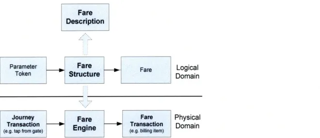
2.1.2 What is a Fare Engine?
A fare engine is the part of an automatic fare collection system that physically implements the fare structure of a transit agency. As such, the input and outputs of a fare engine are consistent with the logical representation of a fare structure. The parallelism between a fare engine and a fare structure is shown in the diagram below. In chapter 3 we will examine what constitutes a fare structure and create a model for TfL's fare structure.
Fare Description
Parameter Fare Fare Logical
Token Structure Domain
Journey Fare Fare Physical
Transaction Enine Transaction Domain
(e.g. tap from gate) ng item)
Figure 2.2 - Generic view of a fare engine as the physical manifestation of a fare structure within an automatic fare collection system.
2.1.3 Example of a Simple Fare Collection System
Below is an example of a very simple bus-only agency which uses a magnetic-stripe based fare collection system. The purpose of this example is to demonstrate the components of Figure 2.2 in a concrete context and show how they fit together.
Fare Description
The fare description is a simple statement explaining fares and rules. "Every boarding costs $1.50. There are no transfers or concessions." Fare Structure
Following the model for fare structures defined in chapter 3.2.1, the fare structure is a matrix with only one tier, labeled 'Fixed Fare'
Fixed Fare $1.50
Figure 2.3 - Fare structure for our very simple fare collection system.
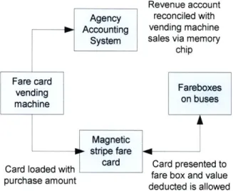
Fare Collection System
The fare collection system is summarized in the diagram below.
Revenue account reconciled with vending machine sales via memory
chip
Card loaded with card Card presented to purchase fare box and valueamount
purchase amount deducted is allowed
Figure 2.4 - Simple magnetic stripe fare collection system.
Fare Engine
Start (Accept Card)
ReadCardValue
[Value >= $1.50] [Value < $1.50]
Subtract $1.50 Card Value? from Value Deduct Fare
Accept Boarding Reject Boarding
Green Light, Red Light,
Sound 'Ding' / Sound 'Beep'
Terminate
In this example, the fare engine resides in a fare box mounted inside each bus near the entrance door. These fare boxes are electro-mechanical devices with a mechanism to ingest, read, write and eject fare cards. The extreme simplicity of this example allows us to express the fare engine as a simple activity diagram. However, in a real-world fare collection system with a more complicated fare structure (no less TfL, which has an extremely complex fare structure), the fare engine is itself a system and will in turn be composed of multiple functional elements.
2.2
Research Question
The research question addressed by this thesis is:
Is it feasible to develop afare engine capable of accepting and processing contactless bankcards as a fare instrument on the TL network while satisfying current and future fare structure and performance requirements?
Information infrastructure is a key component for TfL's Future Ticketing strategy of bringing bankcards as a fare instrument to the London public transportation network. While contactless
bankcard technology is similar to the existing Oyster system in many respects, it also brings new data paradigms, such as a centralized data model, as well as new features and limitations. A fare engine
capable of reconciling these differences with the business requirements inherent in TfL's complex fare structure is a critical component in any future contactless bankcard based fare collection system.
2.3
Investigative Process
In this thesis we seek to produce a functional design of a fare engine for contactless bankcards. In the course this design process, we will develop solutions for challenges arising from both the
characteristics of contactless bankcard technology and the complexity of TfL's fare requirements. The sequential steps of this investigative process as it relates to the structure of the thesis are
summarized below.
1. Identify and formalize the existing TfL fare structure.
2. Formulate a set of system requirements for a contactless bankcards on the basis of the current structure and future needs of TfL.
3. Design a system architecture for a fare engine which satisfies the established requirements. 4. Develop system design details, including data structures and algorithms with a view of
achieving performance requirements.
5. Consider issues surrounding the implementation of the system, or a subset as a demonstrative prototype.
2.4
Development Considerations
Throughout the process of developing a fare engine, and particularly in the system design steps (steps 3 and 4) we are constantly mindful of the following considerations.
* How well can the system cope with expected features and demands of a future fare structure? * Can the system handle high transaction volumes, tight transaction time limits and complex
journey, tap and fare rules?
* Can off-the-shelf software, such as a commercial rules engine, meet the requirements? * If not, can custom software be designed and developed to meet the requirements at an
acceptable level of complexity?
* What are likely the system and hardware requirements of this software?
3 Current TfL Fare Structure
3.1 Fare Description
We define a fare description to be documentation listing fares charged and a corresponding set of rules that apply to these fares. A fare description may be published in any convenient form.
At TfL, fares are published periodically for public information in a series of pamphlets, such as the TfL Guide to Fares and Tickets [1 & 2]. For the use of its staff, TfL publishes the same information in greater detail as a manual, the Staff Guide to Fares. A simplified explanation of fares is also provided on the TfL website [3]. Together, this body of documentation constitutes the de-factofare description for TfL. It describes the fare products which are available to the public in the form of fare tables, and elucidates the rules surrounding the application of these fares.
The fare description is augmented by an incomplete set of internal design documents for the Oyster system. These documents have proven useful for clarifying lesser known rules and fare services, however they are by no means definitive and can only be interpreted judiciously.
3.1.1 Lateral Consistency
TfL's fare description is thus operationally defined by pamphlets produced for passenger and staff information. As such, the fare description is stated in terms of use cases for these different target audiences. Although a use-case presentation is adequate for the purpose of user information, from an analytical perspective, a property we will call lateral consistency is desirable.
To clarify what we mean by 'lateral consistency', let us consider the organization of the 2009 edition of the Guide to Fares and Tickets, an outline of which is attached as Appendix 1. This document is differentiated at the root level into 'Adult', 'Discount', 'Visitor', 'River Rover' and '3 Day
Travelcards'. It is not difficult to see that '3 Day Travelcard' does not belong in the root tier, and has presumably been attached there only as an afterthought; this is an example of lateral inconsistency. As another example, consider the Discount root branch. It is first broken down by ticket type (single or period), and then by mode, and then by discount groups, and last by fare media. Contrast this with 'Adult' fares which are broken down by ticket type and mode, and then immediately by fare media.
The consequence of this discrepancy is that the same attribute, fare medium, is 4 levels deep in the Adult branch but 5 levels deep in the Discount branch.
Note that some single products are available in peak and off-peak formats (e.g. Adult single), while others come in only one variety (Child single). A similar observation is that some discount groups enjoy I-Day products in both Travelcard and capping formats, while others (such as 16+) can only access 1-Day products in the capping format.
Finally, longer-range period products are available as 'Travelcards' only. Capping does not exist for periods longer than one day. Yet, longer duration Travelcards are frequently loaded onto an Oyster card, something that is not possible to do with a 1 -Day Travelcard. The notion of a 'Travelcard' is a blurred one and the term itself is overloaded with multiple meanings.
The above is a partial and informal survey of TfL fare documentation; however it already reveals how the TfL fare description does not clearly indicate the factors that affect fare and how they interrelate.
3.2
General Fare Structures
3.2.1 What is a Fare Structure?Based on the examples above, we recognize that the current articulation of TfL's fare description is difficult to apply systematically. In order to engineer a fare engine for contactless bankcards that assesses fare accurately for trips made by its users, we must first develop a more consistent
understanding of how fares work at TfL, and synthesize this understanding into an applicable framework. We call this framework a fare structure.
Let a fare structure be defined as a representation of fares that can applied systematically and implemented programmatically. We want the fare structure to be a procedure into which we can input known facts about a user's travel, and in turn obtain the price to charge. Examples that would satisfy this requirement include trees, flow diagrams, lookup tables, and multi-dimensional matrices. After a close reading of documents making up TfL's fare description, one could in fact construct a tailor made flow chart (or software logic) that accurately models the fare description, with all its peculiarities. By our definition so far, this would indeed constitute a legitimate fare structure in that
it can be applied systematically. However, such a piece of logic would contain all of the
inconsistencies listed in section 3.1.1, and suffer corresponding drawbacks. For example, a decision tree with the same property represented at different levels would be hard to maintain against even a minor reorganization of fare-impacting properties.
3.2.2 Fare structure Evolution
To refine the concept of a fare structure, let us first pose two fundamental questions relating to what we want to achieve with a fare structure.
* What factors affect the fare?
* How do these factors affect the fare?
To answer these questions, let us lay out some essential nomenclature. This nomenclature is
necessary as we find the term fare structure easily overloaded with conflicting meanings in multiple contexts.
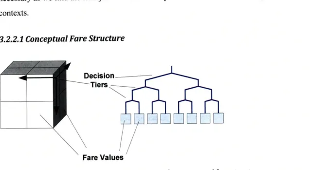
3.2.2.1 Conceptual Fare Structure
Decision
Tiers
Fare Values
Figure 3.1 - Matrix and full tree representations of a conceptual fare structure.
Previously we stipulated a fare structure to be a procedure for fares that can be systematically applied and programmatically implemented. Now we add an additional stipulation, that this fare structure is a multi-dimensional matrix. We call this a conceptual fare structure. Note that conceptual fare
structure is simply the notion of describing fares in a multi-dimensional matrix. It does not specify what this matrix should look like, how many dimensions there are in the matrix, or what these dimensions should stand for. A conceptual fare structure can be equivalently represented as a matrix
or a full' tree, as shown in the figure below. In the matrix representation, the decision tiers are the axes of the matrix while the fare values are the cells of the matrix. In the tree representation, the decision tiers are the non-leaf nodes of the tree, while the fare values are the bottom leaf nodes.
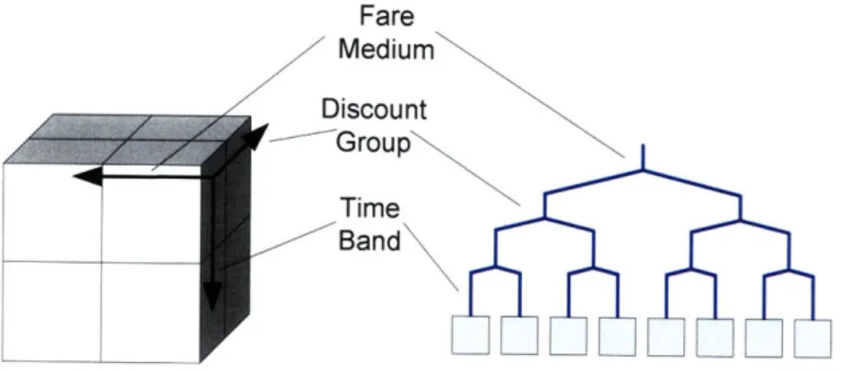
3.2.2.2 Parameterized Fare Structure
The conceptual fare structure is extended into a parameterizedfare structure by specifying what the decision tiers are. In the matrix representation, this means defining the number of dimensions there are in the matrix and the names of these dimensions, or what they stand for. Under the full tree representation, this means specifying the number of levels in the tree and the names of each of these levels. We will call the set of names for the tiers of a parameterized fare structure the fare structure's tier definition. Contextually, a parameterized fare structure describes what properties affect the fare, but not the specific values these properties may take.
Fare Medium Discount Group Time Band
Figure 3.2 - Matrix and full tree representations of a parameterized fare structure.
From now on, the terms tier and dimension will be used interchangeably. Note that although the matrix structure implies no specific order in which dimensions are evaluated, we may nonetheless specify a preferred customary order based on practical considerations.
3.2.2.3 Domain-defined Fare Structure
We define the set of possible values for each tier of a parameterized fare structure to be the tier's tier domain. Furthermore the set of tier domains for the an entire parameterized fare structure is the
A full tree is one in all leaf (terminal) nodes are at the same depth and same level. Furthermore, all possible leaf nodes are defined (the bottom level is complete and has no gaps).
structural domain of the parameterized fare structure. This is akin to defining the input domain of a mathematical function. In a tree representation, these are the labels of the branches at each level. The end result of assigning the structural domain of a parameterized fare structure is a domain-defined fare structure.
When fare structure is spoken of without a qualifying adjective in the remainder of this chapter, a domain-defined fare structure is assumed.
Oyster Cash
Child Adult
Oyster Cash
Peak
Adult Child Adult Child
PO P0 O P0 P0 PO Off-Peak
Figure 3.3 - Matrix and full tree representation of a domain-defined fare structure.
3.2.2.4 Initialized Fare Structure
A domain-defined fare structure gives us a lot of information about how fares work; however it is not a complete specification of fares. The actual fare values need to be loaded into the structure. In the matrix representation, this means filling in the body of the matrix. In a full tree representation, this means populating the leaf or terminal nodes with fare values. We call the product of this step an initialized fare structure. Now the fare structure is ready for direct application.
Oyster Cash
Child Adult
Oyster Cash
Peak £2.20 £2.50
Adult Child Adult Child
Off-Peak £1.20 1.50 P
22 1.2 1.0 0.5 2.5 1 2.0 1.0
3.2.3 Applying a Fare Structure
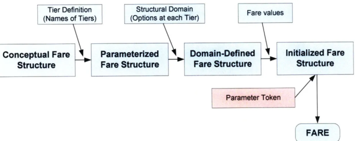
A fully initialized fare structure categorizes fares using a well defined set of parameters. These are parameters that pertain to the properties of the user and the geographic and temporal aspects of the user's journey. In the case of period products2, the parameters pertain to the nature of the ticket and the geographic and temporal aspects of its validity. Parameters are presented to the fare structure as a
unit called a fare parameter token. The number of parameters in a token should be consistent with the tier definition as described in section 3.2.2.2. The value of each parameter should be consistent with the structural domain as described in section 3.2.2.3.
Tier Definition Structural Domain Fare values
(Names of Tiers) (Options at each Tier)
Conceptual Fare Parameterize Domain-Defined Initialized Fare
Structure Fr S c F Stuttrtur
FARE
Figure 3.5 - A fare structure is built up through successive definition with agency-specific information.
3.2.4 Normalization of Fare Variation
Different fares are charged for different journeys. These fares are chosen from a set of fare values which are set arbitrarily. For example, the fare differential between a ticket for travel between
stations A and B and one for travel between stations A and C may be determined by economic and operational factors of the agency. Similarly the amount of discount offered to certain subsections of the population, such as children, the elderly or the unemployed may stem from political
considerations. This variation lies outside the scope of the fare structure to explain. From the perspective of the fare structure, the values are set exogenously.
2 Examples of period products include daily, weekly and monthly tickets. The term period product is defined in
As a guiding principle, the goal of a good fare structure is to explain all possible fares using the smallest number of exogenously defined fare values. Consider the extreme case of a fare structure where all fare variation is exogenous -an unmetered gypsy cab where every fare could be different.
The fare could vary based on the driver's perception of the passenger's willingness to pay or how much he feels a particular trip is worth making for him at that given instant. In either case, any apparent regularity would merely be coincidental.
Clearly, such a system is unsustainable for public transportation. We can inject order into this structure by stipulating that the fare is a function of the passenger's demographic. Let us call this 'passenger class'. This is a 1 -tier definition, indicating that the fare structure can be represented by a 1-dimension matrix. Furthermore we stipulate which classes a passenger must belong to; for
example, PassengerClass e {Adult, Child, Handicapped}. This is our structural domain. Finally, we instantiate the fare structure with fares for each passenger class. Note that we have now moved from one extreme of supplying an infinite number of fare values exogenously (the gypsy cab example), to the other extreme of supplying only 3 possible fares values. A single tier fare structure like this is in
fact an accurate fare structure for many transit agencies. However in other cases greater sophistication is required.
3.2.5 Fare Structure Implementation
We note that the fare structure is a logical product which does not imply an implementation. The fare structure can be implemented in many physical forms, for example, as a printed ticket guide (a fare description). It can be implemented as a piece of software logic (a fare engine) inside a smartcard reader or a ticket vending machine. To support contactless bankcards, we will need to implement the fare structure as a fare engine on a central server. An implementation may only support a subset of the fare structure; for example, an Oyster reader only needs to support the part of the fare structure that pertains to Oyster based products.
Furthermore, an implementation of a fare structure need only provide functional equivalence, and does not have to bear any data model resemblance to the fare structure on which it is based. Our fare structure defined as a multi-dimensional matrix may in fact be evaluated in real-time from a smaller set of data. For example, a fare structure may define adult and child fares as two distinct branches, but in practice the child fare could simply be computed as one half of the adult fare, which is stored.
3.2.6 Limitations of a Matrix Based Fare Structure
Many intricacies of fare cannot be expressed fully using only the multidimensional structure proposed here. For example, TfL fares between origins and destinations are largely distilled into a system of fare zones. Yet there exist many exceptions to the zonal system that prevents the
straightforward use of a zonal origin-destination (OD) matrix. Likewise, out-of-station interchange and capping are peculiarities that defy framing into a matrix. These features can only be described algorithmically.
In this chapter we will explore how fare matrices can be augmented with helper logic and reference tables in order to convey the full complexity of the TfL fare structure.
3.3
Organization of a TfL Fare Structure
Based on the above discussion of the properties of fare structures, we now construct a fare structure for TfL that is consistent with its fare description.
Oyster Based
- - - ---
---Magnetic
Cash Single Extension Stripe
FaresBased
Single Products Period Products
Figure 3.6 - TfL fare structure overview. The two product spheres are shown.
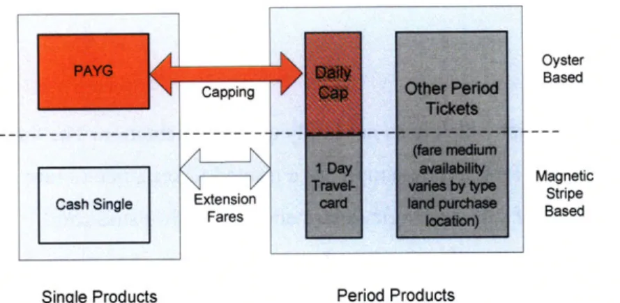
3.3.1 Product Spheres
We define a product sphere to be a set of products or services that can be organized into one multi-dimensional matrix. Using this definition, we can divide the TfL fare structure into two distinct
product spheres. These are single products and period products. Single products encompass Oyster
Pay-As-You-Go (PAYG), as well as cash single (one-way) fares. These are fares which are charged on a trip-by-trip basis. On the other hand, period products represent those products which give
necessary because single products and period products are fundamentally different enough that they cannot be selected using the same set of parameters.
3.3.2 Hybrid and Bridging Features
The Oyster daily cap is a feature that does not fit easily into this dichotomous structure. On the one hand, the daily cap is an integral part of Oyster PAYG, which resides in the single products sphere. On the other hand, it is functionally similar to a period product and has a pricing structure analogous to that of a 1-Day Travelcard. For the latter reason we have classified the daily cap into the period sphere, recognizing however that it is really a hybrid. This is illustrated in Figure 3.6. In the remainder of this document the daily cap will be discussed as a period product.
The two main bridging mechanisms of Figure 3.6 are capping and extension fares. By a bridging mechanism it is meant that these features provide a linkage between the two product spheres. Capping, for example, is the mechanism that offers the period benefits of a daily cap to users of PAYG. This feature is available only for PAYG (not cash singles) and applies only on a daily basis; hence it is represented as an arrow connecting the internal boxes of PAYG and Daily Cap in the diagram. The rules of capping will be discussed in greater detail.
Extension fares, the second bridging mechanism, allow holders of period products to travel outside their zonal validity by purchasing a single product to extend their preexisting ticket. It is another mechanism that connects the two product spheres. In this case, because extension fares can be purchased both by holders of paper tickets, as well as by users of Oyster (in which case, it is applied
automatically), the arrow representing the feature bridges the outer boxes encapsulating an entire sphere.
3.4
Single Products
The payment of single or one-way fares via a prepaid balance deposited on an Oyster card is known as Pay-As-You-Go (PAYG). Individual trips can also be paid for via magnetic stripe based "cash singles". As the fare structures for these two payment methods are very similar, they are considered under the same umbrella sphere of single products.
![Figure 1.2 - Bankcard payment processes. Source: Smart Card Alliance/Booz Allen Hamilton [7]](https://thumb-eu.123doks.com/thumbv2/123doknet/14725909.571766/20.918.89.797.433.741/figure-bankcard-payment-processes-source-smart-alliance-hamilton.webp)