HAL Id: hal-02485073
https://hal.archives-ouvertes.fr/hal-02485073
Submitted on 25 Feb 2020
HAL is a multi-disciplinary open access archive for the deposit and dissemination of sci-entific research documents, whether they are pub-lished or not. The documents may come from teaching and research institutions in France or abroad, or from public or private research centers.
L’archive ouverte pluridisciplinaire HAL, est destinée au dépôt et à la diffusion de documents scientifiques de niveau recherche, publiés ou non, émanant des établissements d’enseignement et de recherche français ou étrangers, des laboratoires publics ou privés.
Stable control for mixed-mode concrete fracture
A. Carpiuc, C Jailin, M. Poncelet, K. Kazymyrenko, F. Hild
To cite this version:
A. Carpiuc, C Jailin, M. Poncelet, K. Kazymyrenko, F. Hild. Stable control for mixed-mode concrete fracture. Technological Innovations in Nuclear Civil Engineering (TINCE), Sep 2016, Paris, France. �hal-02485073�
Full paper Submission, TINCE-2016
Paris (France), September 5
th–9
th, 2016
Stable control for mixed-mode concrete fracture A. Carpiuc1, C. Jailin2, M. Poncelet3, K. Kazymyrenko1, F. Hild4 1Research Engineer, EDF Lab, Palaiseau, France ([email protected]) 2PhD Student, LMT-Cachan, ENS Cachan/CNRS, Cachan, France
3Assistant professor, LMT-Cachan, ENS Cachan/CNRS, Cachan, France 4Professor, LMT-Cachan, ENS Cachan/CNRS, Cachan, France
Introduction
The knowledge of the concrete behavior is essential when analyzing the aging and leak-age phenomena of production facilities. On the industrial level the concrete fracture characteri-zation is currently performed through standard experimental tests that are not sufficiently rich to determine in an optimized manner all the corresponding characteristics. First there is a general lack of mixed mode loading experiments that produce non trivial crack paths. Moreover, even for some well defined material properties (as for example critical shear stress) the corresponding loading tests are not sufficiently developed, as the results are too dependent on aggregate dis-tribution and specimen sizes. It means that we are still not able to locally reproduce some specif-ic mechanspecif-ical stresses distribution and repeatedly check it in order to attain necessary accuracy. Therefore an improvement in corresponding measurement technique is still needed.
When studying concrete fracture behavior the main difficulty is related to instable crack propagation. In the past some relevant works in mixed mode fracture were conducted by Nooru-Mohamed [NOO92]. More recently the work was extended employing an up-to-date full-field measurement technique [CAR15].
In this work, we develop a stable crack path control technique that allows “customized” cracking tests creation for the characterization of various materials. Using this technique well instrumented and discriminating mixed–mode crack propagation tests performed on VERCORS concrete samples are presented. Finally we discuss the relevance of these tests for various pa-rameters identification and some possible extension of stable crack path control technique. Eigen stresses loading history map
When analyzing experimental data some common characteristics are usually deter-mined, as for example, force-displacement curves and crack pattern evolution. While crack pat-tern has clear physical meaning force-displacement curves interpretation is trickier as they could be numerous. For a simple experiment as three point flexure a single force-displacement curve is generated and it could be easily analyzed even by non specialist. For more complex experi-ments, for instance, a typical Nooru-Mohamed test, the number of possible force-displacement curves explodes and it becomes much more difficult to conclude which kind of loading was really applied during the test. In order to simplify this analysis we introduce an eigen stresses loading
3rd Conference on Technological Innovations in Nuclear Civil Engineering
TINCE 2016, Paris 5th to 9th September
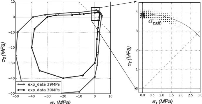
ment is completed we perform its finite elements simulation using a non local damage model. On each loading step the stress field of each Gauss point of the structure subjected to damage evo-lution is recoded. All these data could then be represented on either 2D or 3D eigen stresses maps. We find out that the simplest way is to filter values close to the initial elastic domain and then to plot obtained subset on 2D plane (plane stress or plane strain depending on the experi-ment). For example for three point beam flexure it clearly indicates that during the whole loading mode I stress component (𝜎𝑐𝑟𝑖𝑡 = 3.8 𝑀𝑃𝑎) were probed in priority (𝜎1, 𝜎2) ≈ (0, 𝜎𝑐𝑟𝑖𝑡)
.
Figure 1. Left: two typical initial elastic domains for different concrete types. Right: Eigen stress-es loading history (dots) for three point beam flexure in the bitensile quadrant loading domain. Stable crack control
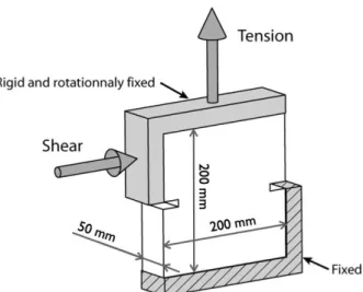
Mixed mode crack propagation could be either generated by the non trivial sample geome-try [BRO96], [WIN01] or by non trivial loading itself. As our main goal is to conduct multiple dif-ferent fracture tests the last approach is more suitable: the easiest Nooru-Mohamed type geom-etry is chosen with the rectangular notched concrete sample mechanically loaded by two rigid steel slabs (Figure 2).
In general flat crack (2D) propagation path control needs the continuous adjustment of at least 2 degrees of freedom: one for uniaxial charging and the second one for crack orientation changing. For the experiments where the loading is applied to the sample through rigid slabs one additional in-plane rigid body motion degree of freedom is also available.
To the extension of the classical Nooru-Mohamed tensile and shear translations we use in our experiments the loading slab’s rotation. The last one serves to apply the supplementary ten-sion-compression gradient loading in front of the crack tip. At our preliminary validation tests the lack of rotation control was clearly identified as an important issue for the crack stability control.
Figure 2. Classical Nooru-Mohamed experiment. The loading is applied to the sample trough two rigid steel slabs using two translational degrees of freedom: tension and shear.
The first option for crack control is a manual change of loading composition on some relevant crack positions. The empirical operator decision based strategy is already non trivial, as one should first be able to measure crack tip position during the experiment and second somehow identify these relevant crack positions. Even so in this article we present two tests that are pre-cisely based on the last strategy, we propose to go further and describe more advanced crack control technique allowing precise crack control. The reason for that is that we have recently realized this kind of tests, but the results are too raw to be presented in the current paper.
Let’s illustrate how the crack orientation could be controlled using Linear Elastic Fracture Mechanics (LEFM) principles. If our system is resorted to just two translational degrees of free-dom (𝑈𝐼and 𝑈𝐼𝐼) then they are linearly related to the couple of stress intensity factors𝐾𝐼, 𝐾𝐼𝐼:
I II I I I I I II II II II II
K
K
K
U
K
K
K
U
Equation 1At each loading step we need to create a finite elements mesh corresponding to the real crack propagation. Then the four elements of the sensitivity matrix are identified using stress intensity factor calculations for two virtual unitary loading:
1
0
and
0
1
I I II II I II I I I I I I I I II II I II II II II II II IIK
K
K
K
K
K
K
K
K
K
K
K
Equation 2The value of stress intensity factors (SIF) are fixed by two previously mentioned criteria: crack initiation at 𝐾𝐼, ≤ 𝐾𝐼𝑐and crack orientation angle fixed by the maximal normal stress condition:
Equation 3
General stable crack control technique follows the same idea of crack reorientation devel-oped just above, taking into account this new stability condition. For each new experiment a
dif-3rd Conference on Technological Innovations in Nuclear Civil Engineering
TINCE 2016, Paris 5th to 9th September
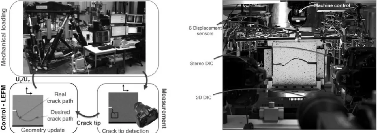
vancement. The testing machine, a hexapod [NIE12], serves to apply three rigid body motions for in-plane loadings, namely, tension, shear and in-plane rotation. High resolution cameras reg-ister full displacement field on both sides of the sample in order get exact crack position at each loading time step. With the proposed experimental setup a new set of benchmark tests for differ-ent loading histories have been obtained. We presdiffer-ented here two of the advanced tests (Figure 4): during the evolution of the crack path, the orientation of the crack were redirected on multiple occasions in certain key positions of the crack tip.
Experimental techniques
Performing more complex tests with crack patterns that present several reorientations or/and bifurcations is made possible by the evolution of the experimental techniques. Combining the use of multiaxial testing machine with 6-axes load-cells and with Digital Image Correlation (DIC) measurements permits to predict the behavior of materials and structures under complex generalized loading conditions. The development of multiaxial loading machines is rather recent, even though these machines have the advantage of applying boundary conditions (controlled in displacement or force) very close to the real-life cases, and also various loading types on the same specimen geometry.
Figure 3
. The 6-axis testing machine. The real setup (left) and the CAD representation (right): (1) base, (2) actuators, (3) moving platform, (4) upper end-effector, (5) room for specimen, (6) optical setup in closed configuration with two cameras, (7) passive hexapodFor the present work a Gough-Stewart platform, a hexapod (Figure 3), is used to perform mixed-mode fracture tests on concrete specimens [NIE12]. The 6-axes loading machine assures both the stable crack propagations and the control of the crack orientation with only three de-grees of freedom, nevertheless the extra loading axes are used to ensure zero displacement along the other directions.
An important experimental challenge is generated by the stiffness of the specimen, the dif-ference of orders of magnitude between the size of the specimen (i.e., 200 mm) and the charac-teristic displacement at failure (i.e., ~20 μm) while the applied loading force goes up to 20 kN. To overcome this challenge and to ensure the required accuracy complex measurements and a specific control of the machine were developed. The 3D control of the machine is assured by a non-contact optical full field measurement technique [FLO14]. Thus a digital image correlation algorithm is used to measure the 3D displacements of the upper-end effector (labeled 4 in Fig-ure 3) and to correct in real time the displacements applied to the specimen.
Another important aspect when performing rich and discriminating mixed-mode crack propagation tests is the use of the Digital Image Correlation (DIC) technique. The displacement fields on each face of the sample, assessed by DIC, give access to the crack pattern, and also to the actual boundary conditions that are crucial for a faithful numerical analysis of the test. Moreover, DIC computations can be performed during the tests to determine the propagation of the crack and adjust the boundary conditions accordingly. This technique was extensively used in this work, and the instrumentation of tests will be presented in the following.
Figure 4.Hybridtest principle (left) and the experimental setup (right).
Instrumentation
In order to have the complete description of the 3D mechanical behavior of the specimen, a 6-axes load-cell (labeled 7 in Figure 3) is used to measure both the applied forces and tor-ques. The cracking state is analyzed on each face of the sample using in plane DIC and the out-of-plane motions are determined using stereo DIC (Figure 4). The displacement fields on each face of the sample give access to the crack pattern, and also to the actual boundary conditions that are crucial for a faithful numerical analysis of the test. Considering the particular control of the machine, by the 3D optical displacement loop, a second measurement setup composed of 6 displacement sensors (Figure 4) to check the applied boundary conditions is installed.
3rd Conference on Technological Innovations in Nuclear Civil Engineering
TINCE 2016, Paris 5th to 9th September
and complex crack patterns are obtained. The shear direction is closely related to the orientation of the crack, the tensile load is responsible for the actual propagation and the rotation increases the stable propagation period by generating a tension/compression stress gradient. Therefore using a multiaxial testing machine coupled with DIC measurements several cases of stable propagation are studied to illustrate phenomena like crack reorientation, crack branching, suc-cessive crack initiations, crack coalescence, crack closure and mode III crack propagation.
In the following, the results of two interactive tests are presented in a succinct manner only to give a hint of the capacity of the developed experimental setup, nevertheless their detailed description is given in [CAR15], all the experimental data and the material characteristics are available. Applied boundary conditions and both tests’ descriptions could be equally downloaded from Code_Aster website (www.code-aster.org, test ssnp168).
The tests are performed on 50x200x200 mm mortar specimens. Depending on the test, two notches (5x40 mm) or only one (5x25 mm) are sawed at mid height of the specimen (Figure 5)
Figure 5. The geometry types: single notch (a), and doublenotches (b)
For the I1 test the loading path is chosen to generate several reorientations and the branching of the crack. It consists of a series of tension, rotation and shear steps (
Figure 6
a) that leads to initiation, propagation and reorientation of a crack following a zigzagged path (Figure
6
b).(a) (b)
Figure 6.
(a) The three elementary loading paths: ‘tension’ (1), ‘shear’ (2) and ‘rotation’ (3),(b)The expected crack path
The crack evolution is controlled by DIC, images are taken every 5 seconds and a DIC computa-tion is performed every 10 images to detect the advancement of the crack. When the crack is
40 40 25 (b) (a) 20 0 10 0 200
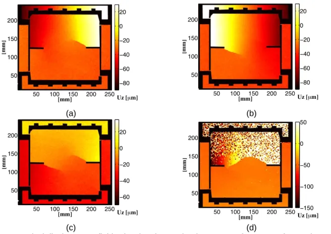
considered sufficiently propagated the loading is changed to reorient/branch the crack. The evo-lution of the crack at the end of each propagation step is given in Figure 7. It is also important to note that the test is quasi-static (i.e., the test lasts more than 10 h with a stable crack propaga-tion during the whole time) so only the final unstable crack propagapropaga-tion is a dynamic event.
(a) (b)
(c) (d)
Figure 7 . Vertical displacement fields showing the crack advancement for test I1 after each propagation step
Test I2 addresses phenomena such as successive crack initiation and propagation, crack clo-sure and friction and crack coalescence. The chosen geometry for the I2 test is the one with two notches (Figure 5b). The test can be divided into four loading steps composed of combinations of elementary loading paths like tension, shear and in-plane rotation (Figure 6a). More in detail the test starts by applying positive in-plane rotation combined with a positive shear force (la-beled 2 in Figure 6(a) to initiate and propagate a crack upward. Afterward, the system is unload-ed and reloadunload-ed by coupling a negative in-plane rotation with a positive shear force leading to the closure of the crack and the initiation of a second crack on the opposite notch. After a sec-ond unloading, the final step is a proportional tensile - negative shear loading that reorients both cracks and joins them. Each combination of loadings is carefully chosen to obtain the aforemen-tioned phenomena (i.e., successive crack initiation and propagation, closure, friction and coales-cence). The evolution of the crack after each propagation step in given in Figure 8.
[mm] [m m ] Uy [mm] Y Z 50 100 150 200 250 50 100 150 200 250 −200 −150 −100 −50 0 [mm] [m m ] Uz [mm] 50 100 150 200 250 50 100 150 200 250 −60 −40 −20 0 20 40 60 [mm] [m m ] Uy [mm] Y Z 50 100 150 200 250 50 100 150 200 250 −200 −150 −100 −50 0 [mm] [m m ] Uz [mm] 50 100 150 200 250 50 100 150 200 250 −100 −50 0 50 100 [mm] [m m ] Uy [mm] Y Z 50 100 150 200 250 50 100 150 200 250 −200 −150 −100 −50 0 [mm] [m m ] Uz [mm] 50 100 150 200 250 50 100 150 200 250 −100 −50 0 50 100 [mm] [m m ] Uy [mm] Y Z 50 100 150 200 250 50 100 150 200 250 −200 −150 −100 −50 0 [mm] [m m ] Uz [mm] 50 100 150 200 250 50 100 150 200 250 −100 −50 0 50 100 150
3rd Conference on Technological Innovations in Nuclear Civil Engineering
TINCE 2016, Paris 5th to 9th September
(a) (b)
(c) (d)
Figure 8Vertical displacement fields showing the crack advancement for test I2 after each prop-agation step.
Finally all experimental tests are represented using earlier introduced eigen stresses loading history map:
Figure 9. Bitensile quadrant zoom of the eigen stresses loading history maps for (from left to right): 3 point flexure, proportional Nooru-Mohamed test, sequential rotation test (I2) and zigzag
type test (I1).
While there seems to be no difference between proportional Nooru-Mohamed test and sequen-tial rotation test, it is clearly seen that zigzag type interactive test (I2) is covering the inisequen-tial elastic yield surface in the most complete way; the last one is also complementary to the 3 point flexure test.
Toward a new kind of custom-made experiments
Path control technique is not always relevant when studying some specific material prop-erty. For example as could be seen from (Figure 9) I2 (sequential rotation test) is not richer than standard Nooru-Mohamed test if one needs just to probe the elastic-domain shape: both have reasonably similar results. Instead of controlling crack path orientation, which is equivalent to stress intensity factor ratio control, another possible way of producing new experiments could be based on the repeated realization of the needed local mechanical loading within the single ex-periment. All three rigid body motion slab’s degrees of freedom are then adjusted in order to reproduce locally (close to the crack tip) some fixed in advance stress distribution just before crack propagation to the next loading step. Thanks to this new approach material property identi-fication accuracy could be refined to obtain necessary precision within a single test.
Conclusion
We propose a new database for concrete fracture analysis of the VERCORS mock-up building. Some most discriminate tests were obtained relying on the developed crack path con-trol technique. By analyzing eigen stresses loading history map we confirm the mixed-mode na-ture of these tests. Their relevance for different mechanical parameters identification is dis-cussed.
References
[NOO92]Nooru-Mohamed, M.B. (1992). “Mixed-mode fracture of concrete: an experimental ap-proach”. PhD thesis, Technische Universteit Delft
[NIE12] Nierenberger, M., Poncelet, M., Pattofatto, S., Hamouche, A., Raka, B., Virely, J. M. (2012). “Multiaxial testing of materials using a Stewart platform: Case study of the Nooru- Mohamed test”, Experimental Techniques 38 (2), 74–83.
[FLO14] Le Flohic, J., Parpoil, V., Bouissou, S., Poncelet, M. and Leclerc, H. (2014). “A 3D dis-placement control by digital image correlation for the multiaxial testing of materials with a Stewart platform”. Experimental Mechanics, 54(5), 817-828.
[WIN01] Winkler, B. (2001). “Traglast untersuchungen von unbewehrten und bewehrten Be-tonstrukturen”, Ph.D. thesis, University of Innsbruck.
[CAR15] Carpiuc, A. (2015). “Innovative tests for characterizingmixed-mode fracture of concrete: from pre-defined to interactive and hybrid tests”. PhD thesis, University of Paris-Saclay.
[BRO96] Brokenshire, D., “Torsional fracture tests” (1996). Ph.D. thesis, Cardiff University.
Please fill in the blanks at the end of this extended full paper (the additional blue lines and potential page it may generate are not accounted in the number of pages)
Preference: � Poster ⊠ Oral
Topic:
⊠
1 - Advanced Materials � 2 - Design and Hazard Assessment� 3 - Civil Works Construction � 4 - Long Term Operation & Maintenance � 5 - Dismantling of civil works & Civil Works in Hostile Environment