Distributed Estimation and Control Technologies
for Formation Flying Spacecraft
by
Philip Andrew Ferguson
Bachelor of Applied Science
-
Aerospace Engineering
University of Toronto, June 2000
Submitted to the Department of Aeronautics and Astronautics
in partial fulfillment of the requirements for the degree of M
Master of Science
at the
MASSACHUSETTS INSTITUTE OF TECHNOLOGY
January 2003
@
Massachusetts Institute of Technology 2003. All rights reserved.
Author ...
...
...
Department of Aeronautics and Astronautics
January 29, 2003
Certified by ...
...
Jonathan P. How
Associate Professor
Thesis Supervisor
Accepted by
. . . .Edward M. Greitzer
H.N. Slater Professor
Chairman, Department Committee on Graduate Students
ASSACHUSETTS INSTITUTE OF TECHNOLOGY
SEP
1 0 2003
Distributed Estimation and Control Technologies for
Formation Flying Spacecraft
by
Philip Andrew Ferguson
Submitted to the Department of Aeronautics and Astronautics on January 29, 2003, in partial fulfillment of the
requirements for the degree of Master of Science
Abstract
Many future space missions, such as space-based radar, earth mapping, and inter-ferometry, will require formation flying of multiple spacecraft to achieve their very advanced science objectives. While formation flying offers many performance and op-erational advantages, there are several challenges that must be addressed, including navigation, control, autonomy, distributed data management, efficient inter-vehicle communication, and robustness. One of the key issues with formation flying of large fleets is selecting the overall system architecture, because it drives the distribution of the various algorithms and the extent to which data must be transmitted.
These challenges are particularly evident with the relative navigation. While carrier-phase differential GPS can be used as a highly accurate sensor for LEO for-mations, it is not sufficient as the sole sensor for missions beyond LEO. If local ranges and range rates are used to augment or replace the GPS measurements, precise es-timation can continue into MEO and beyond. However these new measurements complicate the estimator decentralization by coupling the vehicles' state estimates.
This thesis explores solutions to many of these challenges within the context of the Orion microsatellite formation flying mission. It also presents the Formation
Fly-ing Information Technology testbed, developed to evaluate the communication and
computational requirements associated with various system architectures when using augmented GPS. Several architectures and their associated estimation algorithms are also analyzed and compared in terms of performance, computation, and communica-tion requirements. This analysis clearly shows that the decentralized reduced-order filters provide near optimal estimation without excessive communication or computa-tion requirements. Embedding these reduced-order estimators within the hierarchic architecture presented should also permit scaling of the relative navigation to very large fleets.
Thesis Supervisor: Jonathan P. How Title: Associate Professor
Acknowledgments
In carrying out the research that went into this Master's thesis, there were several key individuals that played large roles in helping me make it to the end. This was a long and difficult road at times and I thank everyone whole-heartedly for their kindness and support over the past two years.
Firstly, I would like to thank my advisor, Professor Jonathan P. How for directing and guiding me through this research. Professor How's strong will and drive for excellence kept me on track, studying new and exciting topics along the way. Professor How taught me the keys to effective research, and for that, I thank him. I also thank Professor How and the NASA Goddard Spaceflight Center for their continued funding through this research project (funded in part under Air Force grant F49620-99-1-0095,
NASA grant NAG5-10719 and NASA grant NAG5-10440).
Next, I would like to thank my research colleagues, among them, Franz Busse, Chanwoo Park, Nick Pohlman, Arthur Richards, John Bellingham, Louis Breger, Ian Garcia, Ellis King and Megan Mitchell. Thanks also to my friend and Professor How's administrative assistant, Margaret Yoon for her support throughout this time. Their help and guidance along the way was completely invaluable to me. They of-fered everything from editing help, to technical and moral support (sometimes over a civilized pint). Thanks all for making this job easier on me.
Throughout my entire life and especially through this time, my parents and brother and sister have always played an important role in supporting me and keeping my spirits up when things get low. Thank you to Mom, Dad, Matthew and Catherine (LYP).
Finally, I would like to thank my beautiful, loving wife, Ally. Her love and support has been absolutely unending through this and every endeavor I take. She has put up with me in the best of moods when everything is working and in the worst of moods when things work less than perfectly. She is my everything and without her, none of what I do would be possible. Thank you Ally. I love you.
Contents
1 Introduction 1.1 Challenges . . . . 1.2 Existing Technologies . . . . 1.3 New Contributions . . . . 1.4 Thesis Outline . . . .2 Orion Hardware and Software Design
2.1 Overview . . . .
2.2 Mission Description
2.2.1 M odes . . . . 2.2.2 Stages . . . .
2.2.3 Resource Budgets . . . .
2.3 The Orion Spacecraft . . . .
2.3.1 Structure . . . .
2.3.2 Propulsion . . . .
2.3.3 Position and Attitude Determination
2.3.4 Attitude Control System . . . .
2.3.5 Command and Data Handling CPU
2.3.6 Communications . . . .
2.3.7 Data Bus . . . .
2.3.8 Power Subsystem . . . .
2.3.9 Science Computer and GPS Interface
2.3.10 Software . . . . 2.3.11 Orion Payload Architecture . . . . .
2.4 M ission Status . . . . . . . . 23 . . . . 25 . . . . 3 1 . . . . 35 . . . . 36 . . . . 3 6 System . . . . 36 . . . . 39 . . . . 4 0 . . . . 40 . . . . 4 0 . . . . 4 1 . . . . 4 2 . . . . 4 6 . . . . 4 8 . . . . 5 0 15 15 18 19 19 21 21 . . . . 2 3
3 The Formation Flying Information Technology Testbed 3.1 Introduction . . . .. . . . . 3.2 Architectures . . . . 3.3 A lgorithm s . . . . 3.3.1 Estimation Algorithms . . . . 3.3.2 Coordination Algorithms . . . . 3.3.3 Formation-keeping Control . . . .
3.3.4 Thrust Mapping and Fault Detection . . . .
3.3.5 Autonomous Task Allocation . . . .
3.4 Example Architectures . . . .
3.4.1 Example Architecture 1 - Centralized Estimator with
uted Controller . . . . 3.4.2 Example Architecture 2 - Decentralized Estimator w"
tributed Controller . . . .
3.5 FFIT Testbed . . . . 3.6 Simulation Results . . . .
3.7 Conclusions . . . .
4 Decentralized Estimation Techniques
4.1 Introduction . . . .
4.2 Centralized Architectures . . . .
4.2.1 Kalman Filter . . . .
4.2.2 Information Filter . . . .
4.3 Decentralized Architectures . . . .
4.3.1 Full Order Decentralized Filters . . . .
4.3.2 Reduced-Order Decentralized Filters . . . .
4.4 Hierarchic Clustering . . . .
4.5 A nalysis . . . .
4.5.1 Two-Vehicle, Two Dimensional Covariance Analysis
4.5.2 Multi-Vehicle Simulation Results . . . .
4.5.3 Data Flow Performance Validation . . . .
4.6 Conclusions . . . . Distrib-ith Dis-5 Conclusions 5.1 Orion 51 51 53 54 55 57 58 60 61 62 62 64 65 69 73 77 . . . . 77 . . . . 79 . . . . 79 . . . . 81 . . . . 82 . . . . 82 . . . . 86 . . . . 89 . . . . 92 92 . . . . 96 . . . . 102 . . . . 108 111 111
5.2 Distributed GNC Architectures . . . . 112
5.3 Decentralized Estimation Using GPS Augmented with Local Ranging 112
5.4 Future W ork . . . 113 5.5 Closing Rem arks . . . . 114
List of Figures
1-1 Algorithmic Structure for Formation Flying . . . . 16
2-1 Orion Mission Timeline . . . . 25
2-2 Orion-Emerald Launch Sequence . . . . 26
2-3 Orion and Emerald on MSDS . . . . 27
2-4 Battery Capacity . . . . 33
2-5 Current Input . . . . 33
2-6 Orion Spacecraft Propulsion . . . . 37
2-7 Orion Spacecraft Avionics . . . . 38
2-8 Orion GPS Receiver . . . . 39
2-9 Orion Science Computer . . . . 41
2-10 Token Bus Electronics . . . . 43
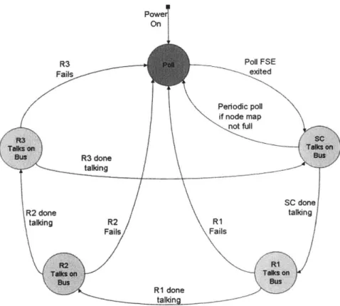
2-11 Token Bus Finite State Machine . . . . 44
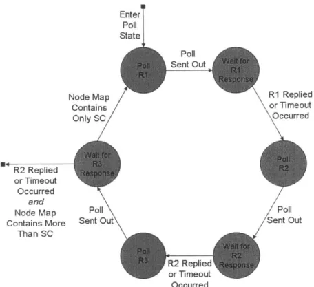
2-12 Polling Finite State Machine . . . . 45
2-13 Orion Software Architecture . . . . 47
2-14 Orion Payload Architecture . . . . 49
3-1 Formation-keeping Control of a Satellite . . . . 59
3-2 Example Architecture 1 . . . . 63
3-3 Example Architecture 2 . . . . 64
3-4 Physical Architecture of the FFIT Testbed . . . . 66
3-5 FFIT Testbed Photo . . . . 67
3-6 Relative GPS Position and Velocity Errors. . . . . 69
3-7 FLOP Profiles for Basic Estimation . . . . 70
3-8 Effect of a Thruster Failure . . . . 71
3-9 FLOP History without using Task Allocation . . . . 72
3-11 3-12 4-1 4-2 4-3 4-4 4-5 4-6 4-7 4-8 4-9 4-10 4-11 4-12 4-13 4-14 74 74 Typical Slave FLOP Profiles . . . .
Bytes Sent from Master . . . .
GPS Estimation with Local Ranging Augmentation
Centralized Algorithmic Flow . . . .
Information Filter Linearization Effect . . . .
Cascade Algorithmic Flow . . . . Hierarchic Clustering Topology . . . .
Two Dimensional Problem Geometry . . . .
Error Ellipse Analysis . . . .
Two-Dimensional Vehicle Motion . . . .
Decentralized Methods Position Error Comparison .
Estimation Error vs. Computation . . . .
Estimation Error vs. Communication . . . .
Estimation Error vs. Solution Time . . . . Scaling Trends for N = 4 . . . . Scaling Trends for N
>
4 . . . .. . . . 78 . . . . 80 . . . . 84 . . . . 85 . . . . 90 . . . . 93 . . . . 94 . . . . 98 . . . . 101 . . . . 102 . . . . 103 . . . . 104 . . . . 106 . . . . 107
List of Tables
2.1 Orion Power Budget . . . . 29
2.2 Orion M ass Budget . . . . 35
Chapter 1
Introduction
The concept of autonomous formation flying of satellite clusters has been identified as an enabling technology for many future NASA and the U.S. Air Force missions [1, 2, 3, 4]. Examples include the Earth Orbiter-1 (EO-1) mission that is currently on-orbit [1, 5], StarLight (ST-3) [6], the Nanosat Constellation Trailblazer mission [7], the Air Force TechSat-21 [8] distributed SAR and the Orion Formation Flying mission [9]. The use of fleets of smaller satellites instead of one monolithic satellite will improve the science return since it provides:
* Coordinated observations from different perspectives.
* Time synchronous observations from spatially distributed instruments.
" Multiple spacecraft to operate as a single instrument.
" Redundancy and reconfigurability in the event of a single vehicle failure.
If the ground operations can also be replaced with autonomous onboard control, this
fleet approach should also decrease the mission cost.
1.1
Challenges
There are many challenges to be resolved before the ambitious objectives described above can be achieved, including modeling fleet orbital dynamics, design of fuel ef-ficient controllers, and development of onboard fleet-level autonomy. Relative nav-igation will also play a crucial role in achieving these mission goals because it will provide the information necessary to perform closed-loop real-time control and the (potentially much more precise) off-line determination of the vehicle relative states for post-processing of the science data.
Local Sensor Data RwSno
Remote Sensor Data Dt
Abolute & Relative State Serial
Data a Ta hruster ^-Handling Inputs
Controller Cont ands
Thrste L - *- High-Level Fleet Co m ad
inputs, Uplink
Down li nk &Crosslink
& Crosslink
I
Data e ce Fleet MonitoringData Monitortn Data Data
__Comm.
IThrusters
SystemCoilsToground and other fleet vehicles
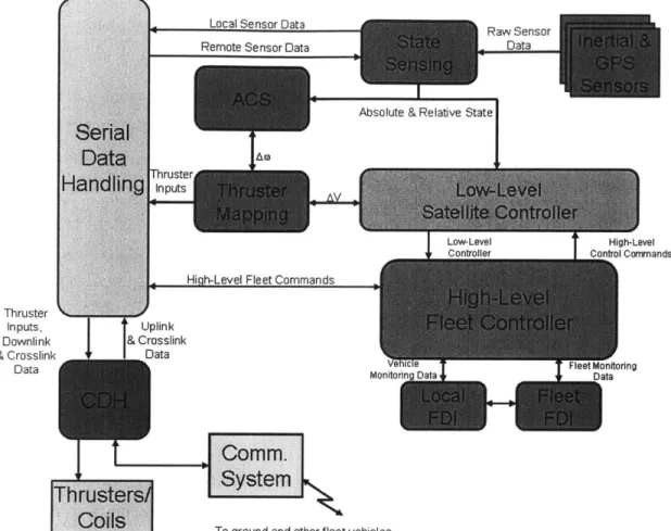
Fig. 1-1: Algorithmic Connectivity Required for Typical Formation Flying Missions.
Future formation flying missions have been proposed at LEO, GEO, in highly elliptical Earth orbits, at L2, and in deep space. While some missions consist of a pair of vehicles (e.g., GRACE and Starlight), others have been proposed with as many as 34 spacecraft (e.g., MAXIM), and some future plans call for missions with as many as 100 spacecraft (e.g., Stellar Imager). Relative navigation for these missions will be challenging because:
1. GPS (a typical "baseline" solution [10]) will not be available at the higher
altitude orbits.
2. Carrier-differential GPS (CDGPS) might not provide sufficiently accurate mea-surements for the science data.
3. The large number of vehicles in the fleet will significantly complicate the
esti-mator design for the relative navigation.
In addition to the the estimation challenges, formation flying is inherently a dis-tributed problem, and achieving the mission goals requires the tight integration of
various algorithms. Figure 1-1 shows the complicated information flow between the various estimation, coordination, and control algorithms for a typical formation flying control system [11]. Several of these algorithms can naturally be decentralized, but others require combined or fleet information, and thus must be performed within a
centralized or hierarchic architecture.
These architectures differ by the degree to which the algorithms are distributed. The raw measurement data for estimation and control is typically collected in a decentralized manner (i. e., each vehicle takes measurements that pertain only to its own state), strongly suggesting decentralized estimators and/or controllers to handle the data. Dividing estimation, coordination, or control algorithms for distribution across the fleet can provide benefits such as improved robustness, increased flexibility, reduced computation time, and improved autonomy. Parallel processing, if scaled properly, could dramatically reduce the computation time compared to a completely centralized architecture. Also, the modularity inherent in distributed architectures usually lends itself easily to expansion.
These benefits of distributed architectures, however, must be weighed against the disadvantages, such as increased inter-spacecraft communications, possible non-determinacy of solutions (synchronization), and higher mission risk stemming from the increase in overall architectural complexity. They key issue here is information management, as significant communication of both raw data (e.g., GPS carrier phase measurements) and solutions (e.g., estimated positions and velocities, coordination requirements) must be shared.
While the issues described above apply to all types of formation flying missions, some of the key challenges to many current and proposed formation flying missions are a result of the mission constraints imposed by the nano- or microsatellites spacecraft designs [9]. The decision to build and fly nanosatellies as part of a formation flying mission is common to many universities, government and military organizations due to their low manufacture cost, ease of operation and small mass (which translates into relatively inexpensive launch costs). However, along with these benefits come the drawbacks of limited power, mass, cost and size restraints. All of these constraints impose restrictions on the bandwidth, communication distance and computational capacity (among others) that can be achieved. While the work presented in this thesis is applicable to control and estimation archictectures for fleets of many different types of spacecraft, the primary focus will be on fleets of nanosatellites, as inspired by the
Orion formation flying mission [9].
1.2
Existing Technologies
The field of formation flying technologies is a very rich one indeed, lending itself to a great many research topics and papers [12, 13]. Work is being done at MIT, Cornell and other universities on navigation and control to prevent collisions, plume impingement and excessive fuel usage. Research is ongoing to invent fault detec-tion and isoladetec-tion routines that can sense failures and reconfigure systems to regain functionality [14, 15]. In addition, highly accurate GPS estimators have been devel-oped to estimate the relative positions and velocities to within 1 cm and 0.5 mm/s
[16, 17, 18]. However, what has yet to be studied is the intricate interactions between
all of the different algorithms required to execute a successful formation flying mis-sion. Furthermore, much of the research to date has focussed on missions in LEO with relatively small fleets (i.e., less than 4 vehicles).
Several testbeds have been developed to focus on demonstrations of the basic formation flying concepts [19, 20, 21], testing the implementation of the real-time code [22] and integrating actual flight hardware in the loop [23, 24]. However, none of these testbeds directly address the inter-spacecraft communication expected on future formation flying missions, which could be a key factor in comparing control and estimation architectures due to the cost, power, mass and expandability issues that arise when choosing inter-spacecraft communication systems for small and cheap microsatellites.
Other formation flying navigation research has focused on augmenting GPS mea-surements with local ranging devices [25, 26, 27, 28, 29]. While useful for extending fleet estimation beyond LEO, the nonlinear measurements, by definition, couple the state estimates of each vehicle, complicating the algorithmic decentralization possi-ble in Ref. [26, 16]. A method for approximating the decentralization was presented in Ref. [26], but its application was limited to ranging devices with accuracy that was similar to CDGPS. Furthermore, the algorithm required multiple iteration steps across the fleet making the method less attractive for large fleets. Other methods of algorithmic decentralization have been explored using information filters [30, 31]. These methods provide solutions identical to the centralized solutions, but require substantial amounts of communication and computation throughout the fleet.
1.3
New Contributions
The work presented in this thesis develops the tools and insight required to verify, test, demonstrate and, in the case of sensing, extend the formation flying technology toolset into a flexible, decentralized framework. This thesis presents the basic requirements of a formation flying mission using Orion as the primary example. A software framework for supporting the autonomous formation flying algorithms is presented along with a description of the key hardware components.
Following a discussion of the required algorithms, a testbed is presented that provides a unique set of capabilities. The Formation Flying Information Technology (FFIT) testbed is shown to be a valuable tool for evaluating the communication and computational aspects of various estimation and control architectures.
The last part of this thesis focuses directly on the problem of estimator decen-tralization in the presence of local ranging augmentation. Several different types of decentralized estimators are compared using the FFIT testbed, including a reduced-order decentralized estimator based on the Schmidt-Kalman filter [32]. Results from the FFIT testbed are presented that indicate the Schmidt-Kalman filter (and its variants) provides the best combination of estimator accuracy, communication and computation. Futhermore, these estimators are shown to be scalable to large fleets using hierarchic architectures.
This research has advanced the field of formation flying by creating an autonomous software framework for the Orion Formation Flying mission, building a testbed to analyze the data flow interactions between the required formation flying algorithms and augmenting the decentralized estimation technologies to make them applicable to future mission scenarios beyond LEO. With the insight gained from the research presented in this thesis, mission designers will be able to better construct control and estimation architectures for large fleets of vehicles in and beyond the range of GPS.
1.4
Thesis Outline
Chapter 2 introduces the Orion Mission in the context of other current and proposed formation flying missions. The Orion timeline and associated activities are presented. Following this discussion, the Orion hardware is presented along with a detailed de-scription of the work done on the software design for the mission.
flying control and estimation architectures from a data flow point of view. Following a discussion of the motivation for and technical description of the testbed, some results are presented from one particular estimation and control architecture to illustrate the usefulness of the FFIT testbed.
The estimation algorithm used to demonstrate the FFIT testbed in Chapter 3 is extended to include local ranging data to augment the measurements in Chapter 4. Several iterative decentralized estimators are proposed that attempt to account for the coupling effect of the nonlinear local ranging measurements and produce estimates that approach the centralized performance. The FFIT testbed is used to analyze the algorithms from a computation and communication standpoint. Chapter 5 concludes this thesis with a summary of my contributions.
Chapter 2
Orion Hardware and Software
Design
The Orion mission was designed to be the first on-orbit demonstration of precise, autonomous, formation flying using Carrier-Phase Differential GPS. Accomplishing this mission using a microsatellite requires a careful design of the hardware, mission plans and associated software. This chapter outlines the status of the Orion spacecraft and mission, as it stood in the summer of 2001, both from a hardware and software design standpoint. However, it should be noted that the Orion mission is still a work in progress and many aspects of the mission are currently undergoing modifications. For the latest developments on the Orion formation flying mission, please consult Ref. [33]. Throughout this chapter, remarks will be inserted to indicate how the latest modifications of the Orion mission may impact the analysis presented here. For the most part, however, much of the analysis is still applicable and only minor changes will be required. The single largest modification to the Orion mission since the writing of this chapter was the replacement of both Emerald spacecraft with a second identical Orion. As will be seen throughout this chapter, this modification primarily impacts the launch sequence and fuel usage.
2.1
Overview
A key step in precise formation flying is developing a sensor and associated estimation
algorithms that can be used to accurately measure the relative positions and veloci-ties of the vehicles in the fleet. GPS can be used to perform these relative navigation
measurements. In fact, using the Carrier-differential Phase GPS (CDGPS), the rel-ative position and velocity measurements can be determined to within 2-5 cm and
1 cm/s in real-time1. One of the primary goals of the Orion mission is to demonstrate this technology on-orbit. Note that several spacecraft formation flying missions have already demonstrated the relative navigation capability using the code-based differen-tial GPS. For example, a GPS receiver was installed on the ORFEUS-SPAS [34] satel-lite that was deployed from the Space Shuttle. A second GPS receiver was mounted on the Shuttle and raw GPS phase measurements were collected by these two re-ceivers. In this mission, 10-50m relative positioning accuracy and meter/sec-level relative velocity accuracy were achieved by post-processing the data. Surrey Space Center [35] has also demonstrated GPS sensing for a formation flying experiment with two spacecraft, SNAP-1 and Tsinghua-1. These two spacecraft carried GPS receivers and demonstrated meter-level positioning capabilities using pseudoranging. However, these two spacecraft computed their absolute positions independently, and relative po-sitioning capability using differential GPS was not demonstrated. NASDA (National Space development Agency of Japan) successfully performed the autonomous ren-dezvous and docking mission of the ETS-VII [36] using code-based differential GPS. They achieved relative position and velocity errors of less than 10m and lcm/sec, respectively. However, the code-based differential GPS was only used in the coarse approach phase due to its relatively poor accuracy. A laser radar and a proximity image sensor were used in the final approach and docking phases. While these results are impressive, the goal of the Orion mission is to extend them by demonstrating the use of CDGPS as the sensing system for very precise relative navigation and formation flying control in real-time.
To accomplish this goal, we have developed, in conjunction with NASA GSFC, a custom GPS receiver that has been tested extensively in various ground testbeds (blimps, robots, racecars) and GPS simulators. This sensing data is then passed to a series of fleet coordination and control algorithms that determine where the vehicles should be located in the fleet and what control commands should be applied to perform the station-keeping. These control decisions will be performed autonomously onboard the Orion spacecraft. Furthermore, we have designed and built a three-vehicle fleet (one Orion and two Emerald spacecraft) to demonstrate formation flying
lThese measurements can then be filtered over longer periods of time to obtain better estimates
on-orbit. This mission was originally conceived in 1996 and has been described in several papers since that time [37, 38, 23, 39, 40].
The first part of this chapter gives a detailed account of the Orion-Emerald mission timeline as well as a description of the analysis to support the mission plan. The second part of the chapter describes some of the key hardware being used on the satellites.
2.2
Mission Description
The mission operations must be carefully planned to meet the goals for the Orion-Emerald mission within the power and fuel constraints. This section presents the mission operation plan, including the mission timeline, from launch to de-orbit. Spe-cial attention is given to the activity of the spacecraft through the mission life, so that resources (such as power and fuel) can be budgeted for the mission. These budgets are given in the next section.
Throughout this discussion, it is important to distinguish between stages, modes, and cycles. Stages refer to distinct segments of the timeline. Modes describe what the satellite is doing at any given time, and may be repeated several times during a stage, or occur during different stages. Cycles refer specifically to a series of modes that will be repeated in a set order. The following discusses the various spacecraft modes and stages of the Orion-Emerald formation flying mission.
2.2.1
Modes
Various modes of operation determine the activity and power usage of the Orion satellite on-orbit. A power usage number is given at the end of each section. These power values were measured on engineering models of the hardware to be flown, so they are known with a high degree of confidence. The modes of operation are:
* Cruise
* Communicate * Active Control * Computing * Stabilizing
The Cruise mode will be employed primarily for recharging the batteries. Many subsystems will be turned off, or set in a low power state. This will allow the solar
cells to trickle charge the batteries. During this time, there will be minimal contact with the Emerald satellites. A single GPS receiver will remain active to provide only absolute state navigation. Power budget: 340mA, 4130mW
The Communicate mode involves the exchange of information with the ground, so it is only active during periods when there is ground station coverage (generally, this will be a brief interruption of another mode.) During this mode, commands can be sent to the formation and telemetry (vehicle and system status) can be downlinked. Also, during the experiment stage, raw data will be sent to the ground for post-processing. This is critical for validation and verification; performance measurement, and to determine mission success. Power budget: 720mA, 8590mW
The Active Control mode is entered any time the propulsion system is used for attitude or translational control. This includes large maneuvers and formation keep-ing. The full GPS suite is required during active control mode since proper thruster usage requires accurate attitude knowledge. Data will continue to be crosslinked be-tween the Emeralds and Orion to allow relative navigation. The Science Computer is also required to perform the computations required for attitude determination, for-mation planning, position control, and thruster mapping. Significant power will be drawn during this mode for thruster activation. Since the active control mode is the most power intensive mode, ground communications mode will not be entered when operating in this mode. Power budget: 2740 mA, 32800 mW
Stabilization mode will occur when the satellite first powers up, or when it is reset for any reason. In this mode the satellite's primary objective is gaining GPS navigation fix, by tracking the required number of GPS signals. This mode will use the magnetometer and magnetic torque coils to de-tumble the satellite (as necessary), thereby enabling the acquisition of GPS signal lock. The ground team will ensure that the GPS fix is acquired before turning the attitude control over to the propulsion subsystem from the magnetic coil subsystem. Power budget: 640 mA, 7630 mW
During the Computing mode, the Science Computer will carry out most of its computationally intensive tasks. Minimal GPS navigation will be employed (no atti-tude), and there is no ground communication. During this mode, optimal trajectory planning will be performed as well as other computationally intensive processes such as data analysis. Power budget: 560 mA, 6680 mW
Remark: In the new Orion mission, each spacecraft (both Orion's) will
have a Science Computer onboard permitting distributed computations
Elliptical Experiments In-track Experiments Formation Stabilization Separagon Checkout Unpowered Idle Time Launch
0
10 20
30 40 50
60 70 80 90
Mission Time (days)
Fig. 2-1: Orion Mission Timeline
2.2.2
Stages
Of course, one of the first stages is the ground preparations which must take place prior to launch. After fabrication, integration, and testing, the integrated Orion-Emerald stack (called Nanosat-1) will be delivered to the launch site. A verification process
will then be done to ensure that all safety mechanisms are functioning properly. In
addition, the team will make final checks and adjustments on the vehicle state. This includes "topping-off' the battery charge, checking/calibrating nominal telemetry
values, and downloading the final software revisions.
Figure 2-2 illustrates the launch sequence from the Space Shuttle and Figure 2-1 shows the expected mission timeline. The mission is predicted to last for 50-90 days
after deployment from the Shuttle. During this period, there are seven operational
stages. The stages are:
1. Launch
2. Ejection
3. Checkout
4. Formation Stabilization
...
Satellites reenter and
t =0
burn up
h
MSDS ejected
Orion-Emeralds on MSDS
-
ALL systems UN-powered
SShuttle Launch
-
Power inhibits unmonitored
Nominal operations:
t
t,
(20 min)
25
-
90 days
-
Orion-Emeralds on MSDS
-
MSDS signal #1 activated
Start-up
*First set of inhibits closed
opertio
p'-Safety-Critical
Systems UN-powered
operations
t t
1+
t
2(20 min + 4 days)
Emeralds
-
MSDS signal #2 activated
-
Second set of inhibits closed
-
ALL systems powered
Emerald Nanosat Stack Inter-Satellite Separation System
"Lightband" Orion Nanosat Stack
(Planetary Systems, Inc.)
CHROMIUM
Inter-satellite Separation Plane
.- Stack Interface Plane (2 PL)
BERYL ORION Stack Separation Plane ( 2 PL)
SHELS/MSDS Plane z
(AFT)
MVSDS
Stack Separation System (Starsys Corp.)
MSDS Baseplat
Fig. 2-3: Orion and Emerald on MSDS
6. Elliptical Experiments
7. De-Orbit
The first stage is Launch. The Orion satellite will be deployed from the Shuttle with the two Emerald satellites on the Multiple Satellite Deployment System (MSDS) platform, designed and constructed by the Air Force Research Laboratory. Figure
2-3 shows the launch configuration [411. The entire MSDS-Emerald-Orion package
(Nanosat-1) will be ejected from the Shuttle using the SHELS launcher in the pay-load bay. The target orbit is 325-350 km altitude and 28.5' inclination, with 0.005 eccentricity. However, 400 km and 500 are preferred parameters, since atmospheric drag severely limits mission lifetime at lower altitudes and higher inclinations increase ground contact visibility times. 'While these are design targets, the exact parameters will, of course, be determined by the Shuttle mission profile.
Extensive work has been done to meet all Shuttle safety requirements, and design-ing for the physical interface. Due to these requirements, Orion will be powered down while on the Shuttle. During all payload and launch vehicle processing, as well as the actual Shuttle launch, the satellites will remain inert. All circuit paths will be broken by a set of latching relays, controlled from the MSDS platform. They are pre-set to close 20 minutes after deployment from the Shuttle. A second set of inhibits block power from reaching Orion's propulsion system. These inhibits will be closed when
Orion and the Emeralds are released from the MSDS platform (approximately four days after Shuttle deployment). These precautions were developed to prevent any
Shuttle re-contact hazards.
The second stage is Ejection. The MSDS shells shelf is ejected from the bay of the Shuttle, at a time determined by the Shuttle mission needs. When the shelf is ejected, the Emerald and Orion satellites will remain attached to the platform and to each other. This package will float for twenty minutes away from the Shuttle before a command is given by the MSDS platform to release the first set of inhibits. The satellite subsystems will then be powered on, while still attached to the platform
(with the exception of the Orion propulsion subsystem.)
Remark: Much of the Launch and Ejection stages will be changed to
accommodate the new mission format. The latest plan as of this writing is to eject one Orion spacecraft from the Space Shuttle cargo bay at a time, separated in time by exactly one orbit of the Space Shuttle, thus removing the need for the MSDS platform. Studies are currently being performed to analyze the feasibility of inserting each Orion spacecraft into similar orbits in this manner without requiring excessive fuel to correct for ejection errors. While this change adds to the complexity of having to match orbit insertions, we gain mission flexibility since each vehicle will have thrusting capabilities (the Emerald spacecraft means of active control is limited to
variable drag). El
The third stage is the Checkout. At this point the satellites are powered, so their performance can be assessed. Communication with the ground and with each other will be confirmed. Power will be collected by the solar panels, which will be used to charge the batteries. Basic telemetry will be downlinked to confirm that operations are normal. The GPS payload will be turned on for all vehicles, and initial ephemeris data for an aided warm start will be uploaded. While the vehicles are still together, a first navigation fix will be attempted. It is possible that the group will be tumbling uncontrollably at this stage, therefore preventing a GPS lock. In this case the ground crew can either attempt to use the attitude control systems on each vehicle to stabilize the group, or just delay the GPS checkout until the vehicles are separated and stabilized.
This stage will last at least four days, allowing the satellites to drift away from the Space Shuttle. The current mission sequence has the payload deployed at the end of
Table 2.1: Power Budget (all values in mW)
Subsystem Cruise Stabilize Comm Active Compute
Payload 1450 1450 1450 6000 4000 CDH 700 700 700 7200 700 Comm 1430 1430 5890 2380 1430 Torquer Coils 250 3750 250 250 250 Propulsion 300 300 300 22400 300 Total 4130 7630 8590 32830 6680
the Shuttle mission. The four days will thus give the Shuttle sufficient time (including
contingencies) to de-orbit and land while Nanosat-1 is effectively inert (NASA safety requirements.) After the four-day period, the second inhibit release command is given
by the MSDS, and the Orion propulsion subsystem will be powered on.
The fourth stage is Formation Stabilization. At this point, the three vehicles are released from the MSDS mounting platform. Using the magnetometer and torquer coils, any initial tumble caused by ejection and release will be damped. Damping any rapid tumbling motion is required to ensure that the GPS sensor can lock on. During this stage, the Orion vehicle will be maneuvered into its first formation position
(100 m in-track separation with the target Emerald vehicle.) Note that the Emerald
vehicles will also attempt to perform formation flying using the CDGPS sensor and differential drag panels [42, 43]. As such, the modes of operation for the Emerald vehicles will be very similar to the ones described in this paper, but the time-scales
will be much longer and the accuracy levels are expected to be much less precise. Future papers will discuss this aspect of the mission in more detail.
This stage will start with the computing and stabilization modes. For the trans-lational maneuver, a short period of active control mode will also be entered. There will also be periods of communication and cruise modes.
The fifth stage is the In-Track Experiments stage which consists of various modes:
" Cruise mode to recharge batteries.
" Communicate mode (single uplink to receive "go ahead"). " Computing mode to plan future actions.
" Active control mode, which includes (i) determining the relative navigation estimate (position and attitude); (ii) commanding thrusters to maneuver to the desired formation; and (iii) actively controlling the formation. The active control mode will be continued for the desired length of time (fuel and power consumption will be closely monitored for anomalies).
* At the termination of the active control mode (either as a result of completing the desired experiment length or due to an anomaly), the vehicle returns to cruise mode. It will then alternate in and out of cruise and communication mode, passing the collected data to the ground (when visible), or just coasting otherwise. This period may also require extensive computing to analyze the performance and change planning parameters based on that performance.
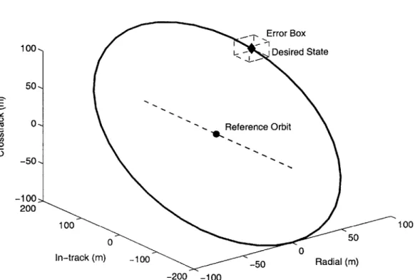
The initial objective will be to demonstrate the control of an in-track formation. There can be a tight, or precise formation, where the Orion remains within a 5mx 1Omx5m
error box centered at a point 100 m (in-track) from one of the Emerald satellites.
A much coarser formation (error box 25m x 50m x 25m) can also be used during this
stage to conserve fuel.
When this first experiment has been successfully repeated several times, a second series of experiments will be performed. In this case Orion will send positioning commands to the Emerald vehicle(s), and using their drag panels, the Emeralds will perform station-keeping maneuvers in cooperation with Orion. This will be repeated until all mission objectives during that stage are completed, or until all budgeted consumable resources are exhausted.
The sixth stage is the Elliptical Formation Experiments. This stage will repeat the same experiment cycles as the previous stage, but will demonstrate different formations. These formations are called elliptical because of the shape of the relative motion between the satellites in a local-vertical local-horizontal frame (radial and in-track) attached to the reference vehicle. If sufficient fuel remains, we will also include a slight cross-track component of this relative motion. For operational description purposes, this stage will be the same as the In-Track Experiment stage. Note that this last experimental stage is optional and will be performed to the extent that time (de-orbit) and resources (fuel) allow. However, it could last as long as 60 days if performed at a low intensity level.
Remark: Note that with the updated mission format, each of the Orion
vehicles will have an approximate AV of 25 m/s, which effectively doubles the mission life-time. The current operations plan for the Orion mission will be to run the experiments as described above using one vehicle as the "active control vehicle" and the other as the "passive drifting vehicle". The vehicles will swap roles to distribute the fuel cost. Fully coordinated maneuvers using two active vehicles will also be performed. Also, note that the 4 day period required by the Shuttle safety team to give the Shuttle time to land may have a significant impact on the new mission profile. Our hope is that with an improved design and more safety analyses of the power and propulsion inhibits, the waiting period can be reduced to limit the drift
between each Orion vehicle. M
The final stage is De-orbit which concludes the mission. Once the experiments are complete, and consumables have been nearly exhausted (with just enough left for de-orbit), the satellite orbits will be decayed to the point where they will re-enter the atmosphere and be entirely destroyed. Due to the small size of the vehicles, no extra precautions are required to ensure debris safety.
2.2.3
Resource Budgets
As with most missions, system resources require careful management and planning. Power, though renewable through the solar cells, still limits the amount of activity on Orion. Fuel, which is not renewable, obviously limits the total mission life. Another important resource is communication bandwidth, and so attention is also given to data transfer budgets.
Power: The power requirements drive the design, frequency, and duration of the
modes of operation. Table 2.1 summarizes the predicted power numbers during the various modes of operation for each satellite subsystem. These numbers reflect the power draw as seen by the batteries. The numbers have been determined by testing engineering models of the actual hardware to be used. Many of the components utilized in the active control mode (GPS electronics, flight computers, and propulsion valves) have high power requirements. The power subsystem was carefully designed to be flexible over a wide range of power levels. The required quality of the solar cells was determined based on these estimated needs, balanced against the spacecraft's available surface area. The key point of this design analysis was that the energy
drawn from the power system while in eclipse is the minimum amount that must be returned during "in the sun" operations.
The average power from the solar cells is 2000mA per panel in the sunlight, which generates a time average of 18.6W to the power bus. The batteries have a 10A-h capacity at 12V. Battery power is required not only for periods when the spacecraft is eclipsed, but also during active control operations when the power from the solar cells cannot power all required subsystems. The battery capacity directly controls the length of any given active control period; the rate of battery recharge directly controls the highest frequency (or quickest cycle time) between active control modes.
A total mission simulation package was created in MATLAB (by B. Engberg [9]),
and it allows for numerous mission parameters to be adjusted. It was used to assess the expected performance of the power system in the various operational flight modes. This simulation accounts for vehicle dynamics, downlink opportunities, and mission resources (fuel, battery capacity, memory). In addition, a scheduling feature allows a wide variety of mission profiles to be assessed.
Figures 4 and 5 show a sample of the output from the simulations. Figure 2-4 shows the available battery capacity over a 36-hour period of mission operations, which includes a demonstration of all flight modes. Note that an active control mode experiment begins on orbit 11 and continues until orbit 15, which supports the desire to safely conduct experiments of this length. The "toothing" in the chart shows how power is drawn from the batteries for about one third of each orbit of cruise mode, when the satellite is in the Earth's shadow. However, this power is easily returned while the satellite is in the sunlight; hence, the power system should be suitable for the designed operations. Figure 2-5 shows the current input from the panels. Note that slow satellite rotations result in peaks and troughs, because the sides of the satellite have more solar cell strings than the top/bottom. However, the average value is around 2000 mA, which is the single-panel target value. Note that Figure 2-5 shows a 3 orbit period.
Fuel: Fuel is Orion's most critical non-renewable resource. Orion has a predicted total AV = 25 m/sec. During the mission there will be a number of discrete, large
maneuvers, as well as periods of active control mode (coarse and precise).
A detailed fuel resource study can be found in Ref.
[9].
By examining thespace-craft resource budgets, it became clear that a careful mission operations plan is re-quired. Maintaining an actively controlled formation uses much less fuel than letting
2 4 6 8 10 12 14 16 18 20 22 Time (orbits)
Figure 2-4: Battery Capacity
6 6.5 7 7.5 8
Time (orbits)
Figure 2-5: Current Input
0 E 4 0. El1 4
the vehicles drift apart and then returning the satellites to formation. However, there is not enough power to constantly remain in active control mode. Therefore, the plan is to stay in active control mode as long as possible, which is on the order of 4 orbits. It then requires about 8 orbits to recharge the batteries to full capacity. Assuming 4 orbits of precision flying and attitude control, using -24 mm/s each, one active cycle uses %100 mm/s. Then, assuming an 8 orbit drift and a 2 orbit repositioning maneuver, which takes r250 mm/s, a total of -350 mm/s of fuel is used per experi-ment cycle. Based on the current control impleexperi-mentation, this cycle of control, drift, and maneuver could be repeated 055 times. At 14 orbits per cycle, and 16 orbits per day, the mission should be able to last for .48 days. Clearly differential drag is a key concern for this mission, and we are investigating ways to reduces its impact.
Remark: The new mission format will contain two identical vehicles, which
will greatly reduce the fuel expense due to differential drag. However, ad-ditional fuel will be required to correct any orbit insertion errors that may
have occurred during the initial ejection stage. l
Communication Bandwidth: Ref. [9] contains a communications bandwidth
analysis for the Orion-Emerald mission. Communication bandwidth is an important resource to manage, particularly in the downlink of data to the ground stations. Data is collected during the formation flying experiments which must be transmitted to the ground to assess mission performance. Downlink capacity must account for both mission data and telemetry. However, ground station coverage for this mission is predicted to be very limited and the communication data rate is only 9600 baud.2
Considering a 28.5', 325 km altitude orbit, there is only 25 minutes of contact time per day (on average, with each overhead pass lasting approximately 6 minutes). This gives an expected 1500 sec/day of data downlink time. Realistically predicting a downlink rate of 2 Kbits/sec (reduction from 9600 baud accounts for overhead, signal-loss and acquisition time), Orion expects only 3000 Kbits/day (or 375 Kbytes/day). Though the Emeralds will have the same downlink capability as Orion, they will be running other experiments as well as formation flying, and have dedicated the majority of their bandwidth to those other experiments.
Given the analysis in Ref. [9], Orion can downlink about 411 samples of GPS data worth of data per day, which places a very tight constraint on the mission. To enhance
2
This design was based on communication robustness considering the power levels and transmit-ter/receiver capability.
Table 2.2: Orion Mass budget Subsystem Mass (g) GPS Payload 1072 Structure 12403 CDH 900 Comm 696 Torquer Coils 2473 Propulsion System 10648 Power System 7140 Total 35332
mission verification, other ground-based approaches will also be used. For just coarse verification, NORAD orbital parameters for Orion and Emerald can be obtained. However, Orion is attempting to demonstrate finer control than the precision of the NORAD orbital elements. By taking concurrent GPS measurements with ground based GPS receivers, the GPS constellation ephemeris can be obtained. This data can then be combined with the data collected on Orion to accurately determine the absolute positions of each vehicle using post-processing techniques (similar to
GIPSY-OASIS). This should enable millimeter-level verification.
Remark: Depending on the capabilities of the ground station, it may
be possible to downlink data from both Orion vehicles at the same time in the new mission format, thus doubling the downlink capability. While this download capability is sufficient to analyze the mission to determine if the goals have been achieved, help will be solicited from additional ground stations to extract as much data as possible from the Orion vehicles. l
2.3
The Orion Spacecraft
The following subsections discuss each of the primary subsystems of the Orion space-craft. Emerald spacecraft are similar in the key subsystems associated with the formation flying experiment. The primary difference between the two spacecraft is that the Emeralds do not have a propulsion system, but rely on differential drag to change their relative positions.
2.3.1
Structure
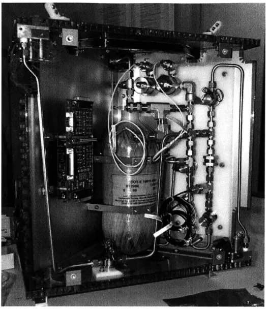
The Orion structure is a 44.5 cm (17.5 in) cube composed of T-6061 aluminum hon-eycomb. The main load-bearing portion of the microsat consists of a top faceplate, a bottom faceplate, and a set of panels that form an internal "X." These honeycomb plates are each 1.27 cm (0.5") thick and are bound together with aluminum L-brackets and stainless steel bolts. Four 0.64 cm (0.25") honeycomb plates cover the remaining four sides of the cube. These panels are non-load-bearing. The solar cells will be bonded to a Kapton-insulated facesheet, which will then bond to the outside panels. Orion's total mass is approximately 35 kg (see Table 2.2).3 Recent vibration tests of an engineering model (EM) of the structure have shown that its natural frequency is 119 Hz. The EM structure has also passed static load tests of 33 g's (along the diagonal) in a centrifuge. Figure 2-6 shows some of the propulsion systems of the Orion spacecraft and Figure 2-7 shows the CPU and some of the GPS payload.
2.3.2
Propulsion
The Orion propulsion system uses GN2 stored in three composite wrapped aluminum tanks. The system is design to provide the satellite with the maximum AV for the given volume and mass budgets. Most of the parts used are COTS parts in order to simplify the manufacturing process. There are 12 cold gas thrusters clustered in four groups of three to provide full 3-axis attitude and station-keeping control. Each thruster has the capability of providing approximately 60 mN of thrust. The 3 cylindrical fuel tanks, each pressurized to 3500 psi are predicted to provide a total AV capability of approximately 25 m/s. The EM propulsion system has been extensively tested to demonstrate that it will meet the Shuttle safety (e.g., verification procedure to show valve closure, and tank certification ) and mission performance goals (leak tests of the high and low pressure sides).
2.3.3
Position and Attitude Determination System
The position and attitude determination system for Orion is comprised of two parts:
A magnetometer (for coarse attitude determination) and a GPS receiver system (with
the capability of determining attitude as well as position). Orion's magnetometer is a
Figure 2-6: Orion spacecraft interior showing some of the propulsion plumbing and control electronics.
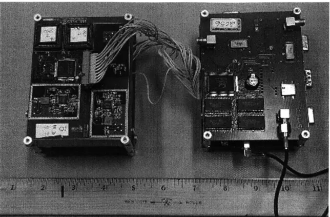
Honeywell HMC2003 3-axis magnetometer with 40 pG resolution. This magnetometer will be used early in the mission as feedback for the torquer coils during detumbling. The GPS receiver for the Orion spacecraft is a modified version of Mitel Semicon-ductor's OrionTM GP2000 chipset [3, 38, 23, 11]. The receiver operates an ARM60 32-bit processor with a GP2021 Correlator with 12 channels tracking the Li band carrier signals. To simplify the attitude determination process, a second RF front end was added to each board. Each RF front end can be programmed to use any of the 12 available correlator channels. Figure 2-8 shows a photo of the modified Orion
GPS receiver. There are total of 6 GPS antennas (3 boards) on the Orion vehicle and
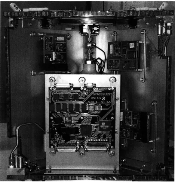
Figure 2-7: Orion internal structure showing CDH CPU (middle bottom),
GPS (top left, right and bottom right), HP prop (middle back)
and LP Prop (lower left and upper right).
Differential Carrier phase measurements should provide very precise relative po-sition estimates between the Emerald and Orion satellites (expected errors on the order of 2-5 cm depending on the geometry). Velocity estimates on Orion will employ Doppler measurements used in the GPS phase lock loop. Doppler measurements can be used as an additional measurement for the estimator rather than a state which is purely an estimated value.
Orion will employ three Trimble Miniature OEM Antennas on the top face, a single antenna on the bottom, and two on opposite sides. Once the satellite de-tumbles, the "top face" should nominally point towards the NAVSTAR constellation
Figure 2-8: Orion GPS Receiver Stack.
and the remaining antennas will provide GPS visibility during maneuvers. The three on the top face form a triangle, which should provide a three dimensional orientation solution. The remaining three antennas were placed to improve the average sky coverage and attitude dilution of precision "ADOP", assuming that a non-aligned
antenna array is used for attitude determination [44, 45]. These attitude and relative
position solutions will be used in the formation and attitude control algorithms.
2.3.4
Attitude Control System
The Orion Attitude Control System (ACS) consists of two distinct subsystems. A magnetic damping controller is included to slow the spacecraft rotation sufficiently for GPS signal to be acquired. This damping might be required at the start of the mission, in the event of loss of GPS, or at the start of a GPS experiment after a period in power-down mode. Dedicated hardware, consisting of a three-axis magnetometer and torquer coils, allows the detumbling to be performed without GPS information. The torquer coils can be seen at the top of Figure 2-7. The control law M = -kB
guarantees energy damping [46] where M is the moment vector, B is the time rate of change of the magnetic field vector calculated in the body frame of the spacecraft,
and k is the gain.
The second attitude controller uses the GPS attitude solution and the thrusters. It is designed to keep the top face (with three GPS antennas) pointing "up" for the best GPS sky coverage. A Kalman filter is used to estimate the full attitude state (including rates.) These estimates are compared with a reference state generated from the approximate absolute position knowledge to find the error for each axis. Thruster switching rules are then applied to stabilize about the reference attitude. The current controller uses AV ~~ 4 mm/s per orbit to maintain pointing within ±450.
Both systems have been extensively tested using full nonlinear attitude models.
2.3.5
Command and Data Handling CPU
The Command and Data Handling (C&DH) system on Orion is responsible for all low-level tasks onboard the spacecraft. These tasks include decoding ground and inter-satellite communication, forwarding commands to distributed subsystems, controlling power switching for subsystems and experiments and gathering health and telemetry data. The CPU will be a SpaceQuest NEC V53 with a 10MHz processor and 1MB of
EDAC Ram. The CPU will be running the Space Craft Operating System (SCOS) by BekTek. Both the CPU hardware and operating system have spaceflight heritage
and are known to perform well. Figure 2-7 shows the C&DH integrated into Orion.
2.3.6
Communications
The communications subsystem on Orion is responsible for handing all data trans-fers between the ground and Orion as well as between Orion and either of the two Emerald spacecraft in the fleet. Crosslink between spacecraft will operate in half-duplex while the down/uplink will operate in full-half-duplex mode. Both crosslink and up/downlink communications will be conducted at 9600 baud. The modems for Orion are manufactured by SpaceQuest. These modems have been used successfully on past spaceflights. The communications system makes use of an omni directional antenna pattern with circular polarization.
2.3.7
Data Bus
The data bus for Orion is the COTS standard by Dallas Semiconductor. The 12C data bus provides a 100 kbps signal rate with multi-master arbitration. This bus
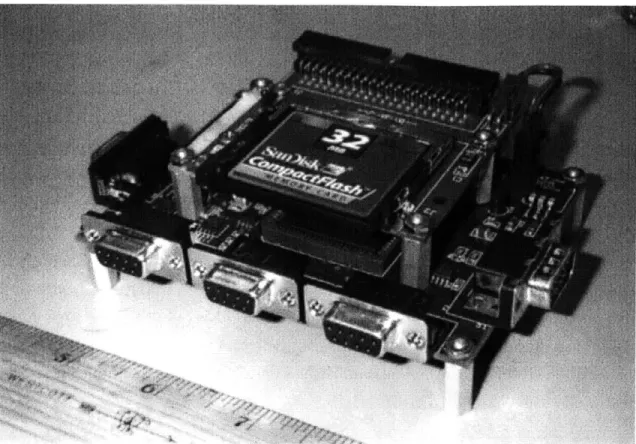
Figure 2-9: Orion Science Computer
will be used to send commands and data to all subsystems on the spacecraft. Most subsystems on Orion will use a PIC board as a bus controller. A bus monitor is also included on the Orion data bus to ensure that all bus activity is operating nominally.
2.3.8
Power Subsystem
Orion will make use of solar energy to charge batteries for power for all subsystems. The power subsystem consists of 6 body-mounted gallium arsenide solar cells (20.6% average efficiency), one 10-cell battery, power safety inhibits as well as electronics for power regulation, radiation latch-up protection, digital power switching, and voltage, temperature and current monitoring. Orion has 15 strings of solar cells with 8 cells per string. Each string generates 9.3 W on average. The storage cells are Sanyo CADNICA 5 AH KR-5000DEK cells. A battery box has been designed and built that meets NASA's stringent safety requirements. The mass of the entire battery box is 1.1 kg. The family of cells selected for Orion have spaceflight heritage on manned missions.