HAL Id: hal-01006569
https://hal.archives-ouvertes.fr/hal-01006569
Submitted on 15 Jan 2015
HAL is a multi-disciplinary open access
archive for the deposit and dissemination of
sci-entific research documents, whether they are
pub-lished or not. The documents may come from
teaching and research institutions in France or
abroad, or from public or private research centers.
L’archive ouverte pluridisciplinaire HAL, est
destinée au dépôt et à la diffusion de documents
scientifiques de niveau recherche, publiés ou non,
émanant des établissements d’enseignement et de
recherche français ou étrangers, des laboratoires
publics ou privés.
Growth of Cuspate Spits
Frédéric Bouchette, Miguel Manna, Pablo Montalvo, Alexis Nutz, Mathieu
Schuster, Jean-François Ghienne
To cite this version:
Frédéric Bouchette, Miguel Manna, Pablo Montalvo, Alexis Nutz, Mathieu Schuster, et al.. Growth of
Cuspate Spits. 13th International Coastal Symposium, Apr 2014, Durban, South Africa. pp.047-052.
�hal-01006569�
47 Growth of cuspate spits
Growth of cuspate spits
Frédéric Bouchette†, Miguel Manna‡, Pablo Montalvo‡, Alexis Nutz∞, Mathieu Schuster∞, Jean-François Ghienne∞
†Geosciences-M / I3M Université Montpellier 2 / CNRS Montpellier, France
‡ Lab. Charles Coulomb Université Montpellier 2/ CNRS Montpellier, France
∞Institut de Physique du Globe Université Strasbourg / CNRS Strasbourg, France
[email protected], [email protected]
INTRODUCTION
A wide range of large-scale long-standing geomorphic features occur in shallow water environments, from tens of metres of water depth to the shoreline, either in the open sea or on continental settings. Ripples, megaripples, dunes and sandwaves develop in rhythmic or isolated patterns at metre to kilometre scale (Bruun, 1954; Bakker, 1968; Lonsdale and Malfait, 1974; McBride and Moslow, 1991; Reynaud et al., 1999; Lykousis, 2001; Todd, 2005; Raynal et al., 2009; Bouchette et al., 2010; Raynal et al., 2010). Sandbanks are a part of this family of bedforms and include features such as mega-dunes, bars and ridges (Dyer and Huntley, 1999). Some sandbanks, termed shoreface-connected ridges and headland-associated banks, correspond to features that develop seaward from high points connected to the coast (McBride and Moslow, 1991; Dronkers, 2005). They are progading down-drift and they usually extend down to deep waters. Obviously these local shoreline perturbations are associated with an accumulation of sand.
Zenkovitch (1959) first described cuspate spits (Figure 1) as a limited category of shore-connected features that result from symmetrical wind/wave forcings and/or peculiar initial shore configuration (Bird, 1994; Coco and Murray, 2007). Asthon et al. (2001) and Asthon and Murray (2006) proposed that cuspate spits, flying spits and other shoreline features are derived from instabilities inherent in the relationship between alongshore sediment transport and local shoreline orientation. They presented a comprehensive weakly non-linear theory for cuspate and spit dynamics, and gave a striking numerical solution to the problem.
The present work focuses on cuspate spits, also termed foreland spits, cuspate foreland or v-notches (Gilbert, 1885; Gulliver, 1896;
Fisher, 1955; Zenkovitch, 1959), which are slightly symmetrical shoreline-connected features that grow along the shoreline of shallow water environments. Cuspate spits belong to the class of self-similar pattern. That is to say, as the time proceeds, the shoreline varies whilst remaining geometrically similar. From this point, we develop a new formulation for the dynamics of cuspate forelands. We derive a non-linear diffusion equation and an explicit solution for the dynamics of foreland spits. The final objective of this paper is to use the model developed to quantify mean growth velocity of cuspate spits, to contribute to the determination of their age or to the mean longshore diffusivity at their origin. The paper also aims to provide additional ideas on the underlying physics of cuspate spits.
First, we recall the mechanical context driving the edification of cuspate spits, specifying what has been discussed in the literature and what we propose here. Then we present the main steps for the development and the proof of our mathematical model. Finally, we adapt our cuspate model to various simple applied circumstances and initiate a discussion on the physics and origin of cuspate spits.
The Non-Linear Pelnard-Considère Equation
In this work, we make the assumption that seabed and shoreline changes driven by strict cross-shore dynamics smooth and counterbalance over time. We consider that the consequence for the net change in the shoreline position over years is weak (Ruessink and Terwindt, 2000; Marino-Tapia et al., 2007). Indeed, at a long time scale, mean cross-shore profile is assumed to be at equilibrium (Hanson and Kraus, 1989; Dean, 1991), i.e. net cross-shore transport equals zero. The significant contribution to the long term shoreline change is thus from longshore dynamics
ABSTRACT
Bouchette, F., Manna, M., Montalvo, P., Nutz, A., Schuster, M.,Ghienne, J.-F., 2014. Growth of cuspate spits. In: Green, A.N. and Cooper, J.A.G. (eds.), Proceedings 13th International Coastal Symposium (Durban, South Africa), Journal of Coastal Research, Special Issue No. 70 pp. 047-052, ISSN 0749-0208.
The present work concerns cuspate spits: slightly symmetrical geomorphic features growing along the shoreline in shallow waters. We develop a new formulation for the dynamics of cuspate spits. Our approach relies on classical paradigms such as a conservation law to the shoreface scale and an explicit formula for alongshore sediment transport. We derive a non-linear diffusion equation and a fully explicit solution for the growth of cuspate spits. From this general expression, we found interesting applications to quantify shoreline dynamics in the presence of cuspate spits. In particular, we point out a simple method for the datation of a cuspate spit given a limited number of input parameters. Furthermore, we develop a method to quantify the mean alongshore diffusivity along a shoreline perturbed by well-defined cuspate spits of known sizes. Finally, we introduce a formal relationship between the geometric characteristics (amplitude, length) of cuspate spits, which reproduce the self-similarity of these geomorphic features.
ADDITIONAL INDEX WORDS: nearshore, sand spit, Pelnard-Considère, non-linear diffusion equation
www.JCRonline.org
www.cerf-jcr.org
____________________
48 Bouchette et al.
(Allen, 1981; Aagaard and Greenwood, 1995). This assumption is at the origin of the formulation proposed here for the development of cuspate spits.
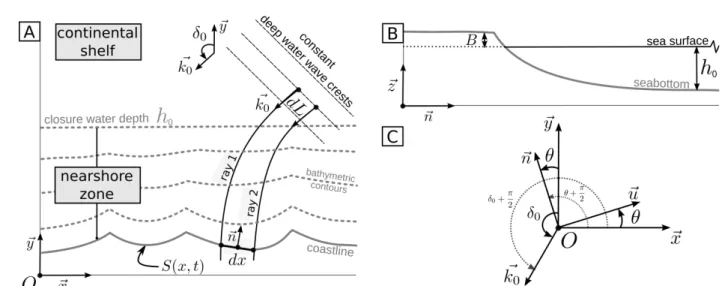
Having this in mind, a basic mass balance equation states that the volume of sand required to move a profile cross shore is the shift of shoreline times the height of the active profile. Let be y = S(x, t) in the equation of shoreline position in a fixed (x, y) coordinate system with the x-axis oriented alongshore, the y-axis oriented offshore and t the time (Figure 2A). S(x, t) satisfies:
0
1
0=
dx
dQ
B
+
h
+
dt
dS
L (1)where h0 is the closure water depth (seaward of which no
significant transport occurs), B is the active berm height, h0 + B is
the height of the active profile (Figure 2B). The total amount of sediment transported alongshore QL is related to the alongshore
flux of energy available for the nearshore per unit length along the shoreline (Inman and Bagnold, 1963):
( )
(
) (
( )
)
p
g
ρ
ρ
x
KF
=
x
Q
s L L−
−
1
(2)where ρsand ρ are densities of sediment and water respectively, p
is the porosity, g is the acceleration of gravity. The dimensionless parametre K is an empiric constant. The energy flux to the beach FL is defined by :
(
δ
θ
) (
δ
θ
)
ε
C
=
F
L g.
0cos
0−
sin
0−
(3)where
cos
(
δ −
0θ
)
is the ratio of incoming energy that flows from the closure water depth through the nearshore to theshoreline. In other words, it is the ratio of energy between two infinitely (dL) close wave rays that acts on an infinitely small dx shoreline segment (Figure 2A). Hence,
sin
(
δ −
0θ
)
is the longshore contribution of the total incoming energy. At the closure water depth h0, the incoming energy is classically defined with theexpression derived from linear wave theory: 0 0
8
1 ρgH
=
ε
with
H
0 representing the wave height. This energy propagates at the group velocity Cg . This velocity must be calculated at thepoint where the energy flows into the active domain, that is at the closure water depth h0. In this case, the linear wave theory
provides the simple formulation: 0
4
π
T
g
=
C
=
C
g g0The longshore transport rate QL is thus:
(
δ
θ
) (
δ
θ
)
=
Q
L2C
Lcos
0−
sin
0−
(4) with:(
ρ
ρ
)(
p
)
π
T
K
ρρg
=
C
s L−
−
1
64
0 2 0 (5)Several formulations for the alongshore transport rate were successively derived from Eq. (3) (e.g. Komar and Inman, 1970; Komar, 1971; Bailard, 1984). Reviews and compared analyses of alongshore transport formulae were also performed (Bayram et al., 2001). Here the sediment transport is strictly controlled by FL, the
Figure 1. Examples of cuspate spits along shorelines. (A) Cuspate along the eastern basin of the Caspian Sea, the Garabogazköl Aylagy (Lat: 41.7813301; Lon: 54.3315601), (B) Cuspate in the north-eastern part of the Langandensbyggö peninsula in Island (Lat: 66.3351803; Lon: -14.7930432), (C) String of cuspates along the Lebanon shoreline (Lat: 32.8597276; Lon: 35.0629139), (D) Cuspate morphology combining with the Belmonte river mouth, Brazil (Lat: -15.8595914; Lon: -38.8902677).
Growth of cuspate spits 49
longshore portion of flux of energy
ε0
per shoreline unit length. No matter what type of wave transformation occurs in the nearshore, the only significant information is the fact that δ0−θvaries along the shoreline and that the energy that flows in the nearshore up dip of the shoreline depends upon this. This point of view is quite different from that chosen by other authors (for more explanations, see Ashton et al., 2001).
The combination of Eqs (4) and (1) is a model of long-term shoreline changes S(x, t) under mean wave forcings and mean sediment texture conditions. To date, several strategies have been tested to find solutions for this kind of problem. First, Pelnard-Consideré (1956) (and a significant amount of subsequent literature) linearized the problem so that a single linear diffusion equation describes the planform evolution of S(x, y). More recently, Asthon et al. (2001) and Asthon and Murray (2006) solved the problem numerically with an expression of Q similar (but not equal) to that of Dean and Dalrymple (2002) and introduced a diffusion coefficient that depends on θ (and may be thus negative). Asthon et al. (2001) focussed on rythmic foreland spits. Another striking idea was to introduce some non-linearity with an “expansion of the flow and the bottom perturbations in a truncated series of eigenfunctions of the linear problem” (Calvete et al., 2002; Falquès et al., 2008) which is not discussed here. The latter works concerned more specifically rythmic shoreline patterns like beach cusps. These works argued that shoreline-connected features including foreland spits originate in instabilities. We provide a new solution to the problem.
The angle θ between the local normal to the shoreline and the y-axis (Figure 2C) satisfies:
(
)
(
)
2 2/
1
1
cos
/
1
/
sin
dx
dS
+
=
θ
dx
dS
+
dx
dS
=
θ
(6) and (7)Eq. (4) can be rewritten in the following Eq (8):
(
)
[
δ
θ
θ
δ
θ
θ
]
C
=
Q
L Lsin2
0cos
2−
sin
2−
2cos2
0sin
cos
Developing Eqs (6), (7) in Taylor series until order two in ∂S/∂x , and combining Eqs (1) and (8) results in
2 2 0 0 2 2 0 0
2G
dx
S
d
dx
dS
sin2δ
+
dx
S
d
cos2δ
G
=
dt
dS
(9) This is a nonlinear diffusion equation.When waves are directed along the x-axis (alongshore wind/wave forcings) sin 2δ0 is zeroand Eq. (9) reduces to a classical diffusion equation (Pelnard-Considère, 1956) with G0 the longshore diffusivity. Another way
to obtain Pelnard-Considère is to linearize Eq. (9). For this reason, we could name Eq. (9) the “non-linear Pelnard-Considère
equation". In such a formulation, G0 is given by:
B
+
h
C
=
G
L 0 0 (10)and one will notice that
(
H
,
T
,
δ
,
ρ,
ρ
,
p,
h
+
B
)
G
=
G
0 0 0 0 s 0 (11)which means that G0 is a function of wave properties, sediment
properties and basic geometrical informations.
Derivation of the Cuspate Equation
From Eq. (11) we know that G0 depends upon most of the
‘environmental’ variables of the problem, i.e., those relative to the geometrical context and the forcings. As long term dynamics are mostly driven by mean values averaged to the historical/ geological time scale, we can consider that H0, T0, ρ, ρs, p are
constant through time or that they vary very slowly. In the same manner, h0 + B may not change as sea bottom is always in
equilibrium (Short, 1999, p. 45, Fig 3).
Let us consider the following particular scenario in the frame (0, x, y) (Figure 2A). At t = 0, we have a non perturbed shoreline for x in [−∞, +∞]. At time t0, an x-symmetric and positively defined
perturbation appears that develops on both sides of the origin O and extends in [−xf , +xf ], being zero beyond. The building of
such a cuspate spit supposes that the alongshore sediment transport results from two main dominant forcings varying close enough to δ0 = ±π/4. Under these conditions Eq. (11) splits in two
equations with solutions SR(for δ0= +π/4) and SL(for δ0= −π/4)
satisfying :
Figure 2. Sketches for the design of the mathematical model (A) a plan view of the nearshore and shoreline Wherein the x-axis is oriented longshore and the y-axis is oriented seaward. From deep water, waves (example of Ray 1 and Ray 2) propagate from the top to the bottom of the figure and refract depending upon bathymetric contours (B) Definition of the normal n to the shoreline, the berm height B, and of the closure water depth h0. (C) Relative orientation of vectors and angles used in the paper.
50 Bouchette et al.
(
)
2/ 2 / 0 /2G
sin
/
2
dx
S
d
dx
dS
π
±
=
dt
dS
R L R L R L (12) As one can consider that the two forcings compete through time, we can substitute the real system represented by the two Eqs. (12) by a model based on a distributed solution satisfying :
≥
≤
≤
−
≤
−
−
≤
f f L L f R R fx
x
x
x
dx
S
d
dx
dS
x
<
x
dx
S
d
dx
dS
x
x
=
dt
dS
for
0
0
for
2G
0
for
2G
for
0
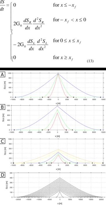
2 2 0 2 2 0 (13)Figure 3. Various cuspate spits calculated from the mathematical model proposed in Equation (16). The different plots correspond to the configurations given below. Parameters to be set are G0 and a.
G0 is given by K = 0.77, ρ = 1025 kg.m -1, ρ
s = 2400 kg.m -1
, H0=1.5 m, T0 = 10 s, κ = 0.55,h0 = 10m. The definition of the
parameter a (arising from the integration) changes in the various plots: (A) parameter a is a constant set to 20; (B) parameter a ranges from 16 to 20; (C) parameter a ranges from 10 to 14; (D) parameter a ranges from 5 to 11; the various curves represent cuspate geometry from 1 year to 450 years.
We already recalled that cuspate spits possess self-similar patterns. Thus it is obvious to take into account the (x,t) dependence of S through a self-similar variable
ξ
so that:( )
x,
t
S
( )
ξ,
τ
S
⇔
with 3 / 1t
x
=
ξ
(14)Applying this variable substitution to the operators d/dx and d/dt, we derive a new writing of Eq. (13):
[
]
[
0]
0 0 00,
0,
3
1
2G
,0
0,
3
1
2G
ξ
ξ
=
ξ
S
ξ
ξ
=
ξ
+
S
ξξ L, ξξ R,∈
−
−
∈
(15)Integrating twice, we obtain another expression with 4 distinct constants to be determined by the geometrical behavior of the cuspate spit. We impose to S to be continuous and positively defined at ξ=0. In addition, we impose discontinuity of the derivative of S at ξ=0. And we impose to S to be zero at the points ξ0 where Sξ=0. We obtain a set of equations with a single
unknown parameter a. Going back to the original coordinates (x,y), we get a new equation.
This equation is an exact solution to the problem developed in Eq. (9) adapted to the growth of any cuspate spit. Figure 3 displays some examples of plots of the expression S(x,y) derived here at various arbitrary times and for various values of the control parameters. Each curve could be cuspate spits like those in Figure 1. The expression of the solution in the original coordinates is given by equation (16) given below.
≥
≤
≤
−
≤
≤
−
−
−
≤
3 / 1 3 / 1 3 3 / 1 0 3 / 1 3 3 / 1 0 3 / 16at
0
6at
0
18t
6a
3
2
2G
1
0
6at
18t
6a
3
2
2G
1
6a
0
t
x
t
x
x
+
t
ax
a
x
t
x
t
ax
+
a
t
x
=
dt
dS
At this stage the model must be developed further. Indeed, unlike the longshore diffusivity G0 which affects the ability of the
system to transport sediment alongshore, the parameter a has no clear physical meaning as it simply results from an integration process. The plots in the Figure 3 are consistent with highly symmetric geomorphic features; but, at this stage, we have no way to use the model for applications.
Using the Cuspate Model
From Eq. (27), the length λ(t) of the foreland spit is :
( )
(
1/3)
6at
2
=
t
λ
(17) For x=0, Eq. (16) results in:( )
( )
(
0)
2 / 33G
/
6
0
=
a
S
(18) Making power three Eq. (28), and deleting a to the power of 3/2 from equations, we get the expression:Growth of cuspate spits 51
( )
t
λ
=
S
.72
2G
0
0 3 (19) If tp is the present time, one may say that0
t
t
=
Δt
p−
(20)is the time required to nucleate and to develop the cuspate spit from an initial moment t0. For convenience, let us rename S(0) as
Ap. With this formalism, Eq. (19) can be rewritten as:
p p
λ
=
ΔT
72A
.
2G
1
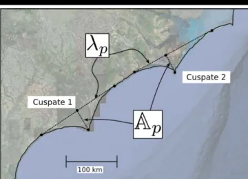
3 0 (21) where Apand λp are the amplitude and the alongshore length ofthe cuspate spit at the present day, respectively. These parameters can be easily measured on an aerial photograph or by satellite imagery (Figure 4) following the simple protocol described below.
Figure 4. Sketch of two cuspate spits along the Carolina Coast, from Asthon et al. (2001). The two cuspates (1 and 2) display well defined wave lengths λp and wave amplitudes Ap. Those parameters can be estimated
with the methodology described in the text.
To quantify Apand λp for a given cuspate, the following method
is applied: a) draw a line at the tangent to the shoreline; it intersects the shoreline in two points. This defines a segment which is the cuspate length λp; (b) from the head of the cuspate
spit, draw the perpendicular line to the segment defined in (a); the point at their intersection and the point at the head of the cuspate form a new segment whose length is the amplitude Ap of the
cuspate spit.
Eq. (21) can be considered as a method for the datation of a cuspate spit knowing the mean alongshore diffusivity and the geometrical features of the cuspate in the present day. Alternatively, the cuspate model can be thought as a tool to quantify the mean alongshore diffusivity G0 having information
on the geometry of the cuspate spit and its age. Indeed, considering that the present day geometry of a cuspate is known, as well as its age Δt (e.g. dated by its occurence in an artificial continental water body damned at a given period; or directlty dated by any well-adapted datation method). This information can be robustly retrieved through field work by geologists. From Eq. (21) it reads directly:
(
ΔT
)
λ
=
p/
72.A
p.
2G
0 3 (22) The calculation of such a mean alongshore diffusivity from parameters expressed on a geological/historical time scale isinteresting for the classification of the paleo-system concerned with respect to well-known existing littoral systems (such as described in Dean & Dalrymple (2002)).
Another obvious application is to calculate the mean active profile (or the mean wave height or period) for the system at a given time knowing the present day geometry and all the other long-term mean forcings. Combining Eqs (5), (10) and (21), we have:
(
)(
)
3 0 2 0 01
2
9K
p s pλ
p
ρ
ρ
π
ΔT
A
T
ρgH
=
B
+
h
−
−
(23) The benefit of this last application could be debated for recent cuspate spits. Indeed, one will claim that there exist other ways of calculating an active profile directly from data in the field (e.g. considering the analysis of wave data at a buoy, and the subsequent extraction of a closure depth). Nevertheless, for ancient cuspate spits it seems obvious that the calculation of0 2 0
T
H
directly from Eq. (23) would provide significant semi-quantitative restrains for the reconstruction of paleo-wave regimes. Indeed, the parameters ρs, ρ and p could be determinedby analysis of sand properties within the cuspate deposits. λp and
Ap could be determined by direct surface observation (or seismic
investigation if the cuspate is buried). h0 could be determined by
the identification of the location where wave ripples vanish and B by the identification of the position of the shoreline and the highest location concerned by wave impact.
DISCUSSION
The cuspate model offers the opportunity to calculate useful parameters for coastal engineering and geosciences. But applications under real conditions are beyond the objective of this paper, although they could be presented in future works.
Nevertheless, the cuspate model highlights a more fundamental result. In their numerical analysis of the growth of cuspate spits, Ashton & Murray (2006) suggested that there exists an approximate relationship between the age and the length of a cuspate feature. They wrote (Eq. (10) in their paper):
2 5 / 1 5 / 12 0 1
H
T
Δx
D
K
Δt
sf
≈
(24) where Δt is our ΔT (the age of the cuspate), Δx2 is λp2 the cuspate
length squared, and Dsf, K1 and other variables can be considered
as constant and are ignored in the following. The authors derived this approximate relationship from the equation at the origin of their numerical model and from an analysis of numerical simulations.
In this paper we demonstrate with Eq. (21) that a formal relationship between the age and the length of the cuspate is mathematically correct, and that this relationship is definitively controlled by a power law as Ashton & Murray (2006) suggested. Although the term to the power is different (3 in our case; 2 in the case of Ashton & Murray), these two totally independent proofs give more confidence in the reality of such a relationship. The occurrence of a power law suggests also that more underlying physics remain to be analyzed.
Finally, Ashton & Murray (2006) sustained the idea that, contrary to a traditional point of view, the wave angle in deep water strongly controls shoreline perturbations through their so-called anti-diffusional high wave angle instability. In this paper we demonstrate that deep water wave features H0 and T0 drive
non-linear shoreline instabilities in a simple way with absolutely no dependance on what occurs to waves in the nearshore. This is also
52 Bouchette et al.
a formal confirmation of what was suggested by Ashton & Murray (2006). Fourth, we demonstrate that there is no need to transform – by quite complex and obscure operations – shallow water variables into deep water ones (Equations (1), (4) and (5) of Ashton & Murray, 2006) to get this result.
CONCLUSION
From what can be called the non-linear Pelnard-Considère equation, we develop an explicit formulation of the growth of a symmetrical cuspate spit through time. This formulation can be applied (a) to the calculation of the age of a cuspate spit, (b) to the determination of a mean alongshore diffusivity in the vicinity of a cuspate spit, or (c) to the calculation of a paleo-active profile or information on paleo-wave regimes after some simple geological field data has been acquired. More substantially, the paper confirms the works of Ashton & Murray (2006) in the sense that it provides an alternative formal proof of what was suggested. In a near future the cuspate model will be more deeply explored, tentatively extended to other geomorphic features and engineering/ geological applications will be engaged to confirm its relevancy.
ACKNOWLEDGEMENT
This work was funded by NUCLEASPIT (CNRS Mathematics and Physics) and by KUNSHEN (ANR international program). The authors thank GLADYS (www.gladys-littoral.org) and SO LTC (www.soltc.org) for the comments on the original work as well as the reviewer of the previous version of the document.
LITERATURE CITED
Aagaard, T. and Greenwood, B., 1995. Longshore and cross-shore suspended sediment transport at far infragravity frequencies in a barred environment. Continental Shelf Research, 15, 1235-1249.
Allen, J., 1981. Beach erosion as a function of variations in the sediment budget, Sandy Hook, New- Jersey, U.S.A. Earth Surface Processes and Landforms, 6, 139–150.
Asthon, A. and Murray, B., 2006. High-angle wave instability and emergent shoreline shapes: 1) modeling of sand waves, flying spits and capes. Journal of Geophysical Research, 111, F04011.
Asthon, A., Murray, B. and Arnault, O., 2001. Formation of coastline features by large-scale instabilities induced by high-angle waves. Nature, 414, 296-299.
Bailard, J., 1984. A simplified model for longshore transport. Proc. 19th Intl. Conf. Coastal Eng., ASCE, Houston, 1454-1470.
Bakker, W., 1968. Mathematical theory about sand waves and its applications on the Dutch Wadden Isle of Vlielan. Shore and Beach, 5-14.
Bayram, A., Larson, M., Miller, H. C. and Kraus, N. C., 2001. Cross-shore distribution of longshore sediment transport: comparison between predictive formulas and field measurements. Coastal Engineering, 44 (2), 79-99.
Bird, E. C., 1994. Chapter 2 physical setting and geomorphology of coastal lagoons. In: Kjerfve, B. (ed.), Coastal Lagoon Processes. Vol. 60, Elsevier Oceanography Series, 9-39.
Bouchette, F., Schuster, M., Ghienne, J.-F., Denamiel, C., Roquin, C., Abderamane, M., Marsaleix, P. and Duringer, P., 2010. Hydrodynamics in the Holocene lake MegaChad. Quaternary Research, 73 (2), 226-236. Bruun, P., 1954. Migrating sand waves or sand humps, with special reference to investigations carried out on the Danish North Sea coast. Proc. 5th international conference coastal engineering, ASCP, 269-295.
Calvete, D., de Swart and H. E., Falquès, A., 2002. Effect of depth-dependent wave stirring on the final amplitude of shoreface-connected sand ridges.
Continental Shelf Research, 22 (18-19), 2763-2776.
Coco, G. and Murray, A. B., 2007. Patterns in the sand: From forcing templates to self-organization. Geomorphology, 91 (3-4), 271-290.
Dean, R., 1991. Equilibrium beach profiles: characteristics and applications. Journal of Coastal Research, 7, 53-84.
Dean, R. and Dalrymple, R., 2002. Coastal processes with engineering applications, Cambridge University Press, 488p.
Dronkers, J., 2005. Dynamics of coastal systems. Vol. 25. World Scientific, 255p.
Dyer, K. and Huntley, D., 1999. The origin, classification and modelling of sand banks and ridges. Continental Shelf Research, 19, 1285-1330. Falquès, A., Dodd, N., Garnier, R., Ribas, F., MacHardy, L., Larroudé, P.,
Calvete, D. and Sancho, F., 2008. Rhythmic surf zone bars and morphodynamic self-organization. Coastal Engineering, 55 (7-8), 622- 641.
Fisher, R. L., 1955. Cuspate spits of saint lawrence island, alaska. Journal of Geology, 63, 133-142.
Gilbert, G. K., 1885. The topographic features of lake shores. US Geological Surv. Ann. Rep., 5, 69-123.
Gulliver, E., 1896. Cuspate forelands. Geol. Soc. Am. Bull., 7, 399-422. Hanson, H. and Kraus, N., 1989. Genesis: Generalized model for
simulating shoreline change. report 1: Technical references. US Army Eng. Waterways Experimentation station.
Inman, D. and Bagnold, R., 1963. New York Interscience, Littoral processes, 529-533.
Komar, P., 1971. The mechanics of sand transport on beaches. Journal of Geophysical Research, 76, 713-721.
Komar, P., Inman, D., 1970. Longshore sand transport on beaches. Journal of Geophysical Research, 75, 5914-5927.
Lonsdale, P. and Malfait, B., 1974. Abyssal dunes of foraminiferal sand on the canergie ridge. Geol. Soc. Amer. Bull., 85, 1697-1712.
Lykousis, V., 2001. Subaqueous bedforms on the Cyclades plateau (NE Mediterranean). Evidence of cretan deep water formation. Continental Shelf Research, 21, 495-507.
Marino-Tapia, I., Russell, P., O’Hare, T., Davidson, M. and Huntley, D., 2007. Cross-shore sediment transport on natural beaches and its relation to sandbar migration patterns: 1. field observations and derivation of a transport parameterization. Journal of Geophysical Research-Océans, 112, C03002. doi: 10.1029/2005JC002894.
McBride, R. A. and Moslow, T. F., 1991. Origin, evolution, and distribution of shoreface sand ridges, atlantic inner shelf, U.S.A. Marine Geology, 97 (1- 2), 57-85.
Pelnard-Considère, R., 1956. Essai de théorie de l'évolution des formes de rivages en plages de sable et de galets. La Houille Blanche.
Raynal, O., Bouchette, F., Certain, R., Sabatier, P., Séranne, M., Lofi, J., Dezileau, L., Briqueu, L., Ferrer, P. and Courp, T., 2010. Holocene evolution of languedocian lagoonal environment controlled by inherited coastal morphology (Northen Gulf of Lions, France. Bulletin Société Géologique Française, 181 (2), 211-224.
Raynal, O., Bouchette, F., Certain, R., Séranne, M., Dezileau, L., Sabatier, P., Lofi, J., Bui Xuan Hy, A., Briqueu, L., Pezard, P. and Tessier, B., 2009. Control of alongshore-oriented sand spits on the dynamics of a wave-dominated coastal system, Holocene deposits, northern Gulf of Lions, France. Marine Geology, 264 (3-4), 242–257.
. and Debatist, M., 1999. Tide and wave dynamics on a sand bank from the deep shelf of the western channel approaches. Marine Geology, 161, 339-359. Ruessink, B. and Terwindt, J., 2000. The behaviour of nearshore bars on the time scale of years: a conceptual model. Marine Geology, 163. Short, A. C., 1999. Handbook of shoreface morphodynamics. Piley and Sons, 392p. Todd, B. J., 2005. Morphology and composition of submarine barchan dunes on the scotian shelf, canadian atlantic margin. Geomorphology, 67, 487-500. Zenkovitch, V. P., 1959. On the genesis of cuspate sits along lagoon shores. The Journal of Geology, 67, 269-277.