HAL Id: hal-02863679
https://hal.archives-ouvertes.fr/hal-02863679
Submitted on 10 Jun 2020
HAL is a multi-disciplinary open access
archive for the deposit and dissemination of
sci-entific research documents, whether they are
pub-lished or not. The documents may come from
teaching and research institutions in France or
abroad, or from public or private research centers.
L’archive ouverte pluridisciplinaire HAL, est
destinée au dépôt et à la diffusion de documents
scientifiques de niveau recherche, publiés ou non,
émanant des établissements d’enseignement et de
recherche français ou étrangers, des laboratoires
publics ou privés.
A story of errors and bias: The optimization of the LGS
WFS for HARMONI
Thierry Fusco, Benoit Neichel, Carlos Correia, Leonardo Blanco, Anne
Costille, Kjetil Dohlen, François Rigaut, Edgard Renaud, Anne Bonnefoi,
Zibo Ke, et al.
To cite this version:
Thierry Fusco, Benoit Neichel, Carlos Correia, Leonardo Blanco, Anne Costille, et al.. A story of
errors and bias: The optimization of the LGS WFS for HARMONI. AO4ELT6, Jun 2019, Quebec
City, Canada. �hal-02863679�
A story of errors and bias: The optimization of the LGS WFS for
HARMONI
Thierry Fusco*
a,b, Benoit Neichel
b, Carlos Correia
b,cLeonardo Blanco
b,d, Anne Costille
b, Kjetil Dohlen
b, François Rigaut
e, Edgard Renaud
b, Anne
Bonnefoi
b, Zibo Ke
b, Kacem El-Hadi
b, Jérome Paufique
d, Sylvain Oberti
d, Fraser Clarke
f,
Ian Bryson
g, Niranjan Thatte
f𝑖𝑎 ONERA, DOTA, 29 avenue de la division Leclerc, 92322 Chatillon, France 𝑖𝑏 Aix Marseille Univ, CNRS, CNES, LAM, Marseille, France 𝑖𝑐W.M. Keck Observatory 65-1120 Mamalahoa Hwy, Kamuela, HI 96743 𝑖𝑑 European Southern Observatory, Karl-Schwarzschild-str-2, 85748 Garching, Germany 𝑖𝑒 AAO-Stromlo, Australian National University, Cotter Road, Weston, ACT2600, Australia
𝑖𝑓 University of Oxford Denys Wilkinson Building, Keble Road, Oxford OX1 3RH 𝑖𝑔 UK Astronomy Technology Centre, Royal Observatory Blackford, Edinburgh EH9 3HJ
ABSTRACT
Laser Guide Star [LGS] wave-front sensing is a key element of the Laser Tomographic AO system and mainly drives the final performance of any ground based high resolution instrument. In that framework, HARMONI the first light spectro-imager of the ELT [1,2], will use 6 Laser focused around 90km(@Zenith) with a circular geometry in order to sense, reconstruct and correct for the turbulence volume located above the telescope. LGS wave-front sensing suffers from several well-known limitations [3] which are exacerbated by the giant size of the Extremely Large Telescopes. In that context, the presentation is threefold: (1) we will describe, quantify and analyse the various effects (bias and noise) induced by the LGS WFS in the context of ELT. Among other points, we will focus on the spurious low order signal generated by the spatially and temporally variable sodium layer. (2) we will propose a global design trade-off for the LGS WFS and Tomographic reconstruction process in the HARMONI context. We will show that, under strong technical constraints (especially concerning the detectors characteristics), a mix of opto-mechanic and numerical optimisations will allow to get rid of WFS bias induce by spot elongation without degrading the ultimate system performance (3) beyond HARMONI baseline, we will briefly present alternative strategies (from components, concepts and algorithms point of view) that could solve the LGS spot elongation issues at lower costs and better robustness. Keywords: Wave-Front Sensing, LTAO, ELT, LGS
1. INTRODUCTION
Most of the current AO system are however constrained by the number of targets available to AO correction (the so-called sky coverage), and the need for statistics that requires observing many objects across the largest possible field. Those constraints called for the development of a new generation of AO, called Wide Field AO [WFAO]. By using multiple Laser Guide Stars [LGS], WFAO significantly increases the field of the AO corrected images, and the fraction of the sky that can benefit from such correction. Very recently, such capability has been brought to its apogee by coupling the ESO-operated Adaptive-Optics Facility (AOF) with the cutting-edge instrumentation of the MUSE integral-field (3D) spectrograph. Similar instrumental capabilities on the ELTs (e.g. HARMONI, MOSAIC) will revolutionize the extra-galactic field, as we will be able to reproduce the observation of the galaxy structure and kinematics out to distances of tens of millions of light-years. This will certainly modify our understanding of the galaxy mass assembly mechanisms and the Hubble sequence build-up. The use of multi-LGS in astronomy is however a young technology, and the extrapolation of the technique to the ELTs sizes leads to technological barriers regarding Wave-Front Sensing and associated detectors. For a LGS system, the artificial reference source is created by shining a laser from the telescope. Light from the beam is absorbed and reemitted by atoms in the upper atmosphere (a Sodium layer in the mesosphere) back into the WFS. However, due to the vertical extension of the Sodium layer (typically 20km), the AO guide star is now an extended object, with a complex shape, and temporally evolving with Sodium layer dynamical variations. When considering SHWFS – which is the baseline of all current LGS-based AO systems - this Sodium layer extension creates elongated spot in each sub-aperture which can be as large as 20” for an ELT. Dealing with such a spot elongation using a classical SHWFS requires a tremendously large number of pixels. It calls for very sensitive
(almost photon noise limited), very fast (larger than 500 Hz, most likely 1kHz) and extremely large (typically 5 million pixels) detectors. Such kind of devices is far beyond existing and first generation of WFAO systems on the ELT (currently in their preliminary design phase) which have to consider lower performance detectors (smaller, slower and noisier). The consequence is a reduced wave front sensing performance, creation of spurious effects and biases (so-called “truncations effects”) and a limited performance of the full AO system. For spectroscopic studies of distant galaxies, reduced AO performance translates in sensitivity loss, or equivalently, it limits the observation of the faintest and more distant objects.
In this paper we will investigate several methods (both from the opto mechanical side and the control side) allowing to deal with spot elongation on an ELT using existing or close to exist detector technology. We will first recall the main problematic related to the spot elongation. Then we will identify possible mitigation and we will thoroughly study a couple of solution in the frame of the HARMONI project. An exhaustive analysis will be done on a downscaled version of the ELT (in order to fasten the simulation) and the conclusions will be apply to the full-scale system.
2. 3D SODUIM LASER GUIDE STAR AND ELT
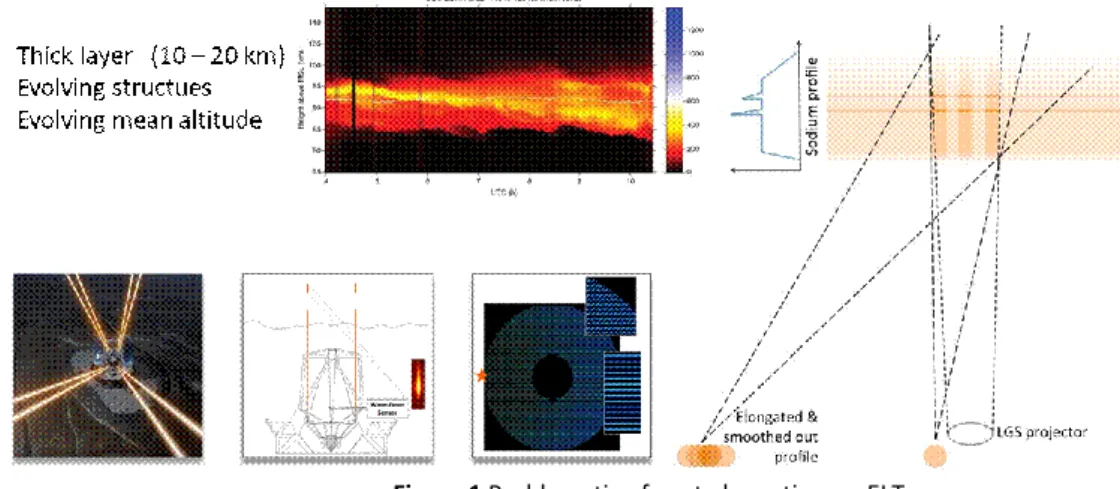
2.1 LGS spot elongationSodium laser guide stars (LGS) increase the sky coverage of adaptive optics (AO) systems. However, the finite height, the double pass through the atmosphere and the elongated size of the LGS, still limits the extent of the sky coverage. Temporal variations of the sodium layer density profile induce errors on centroids of the elongated LGS spots of Shack–Hartmann wave front sensors (SH–WFSs), especially for extremely large telescopes (ELTs) as the spot elongation increases with the telescope diameter. The main aberrations induced by the sodium layer variations are a tip/tilt (if the laser is launch from the side of the primary mirror) and a focus error. These errors are due to the variation of the mean altitude of the sodium layer and must be negated optically by zoom optics in order to keep each LGS spot focused and centered on its sub-aperture. If the laser is launch from the side, non-Centro–symmetric aberrations arise in addition to spherical aberrations, such as astigmatism, coma and trefoil. Square symmetric aberrations are due to: (i) a square truncation of spots by the pixels’ boundaries of each sub-aperture, (ii) the spot sampling by a finite number of square pixels (see Figure 1).
Figure 1 Problematic of spot elongation on ELT
Consequently, all the LGS aberrations beyond the focus are due to instrumental artefacts and must be mitigated. To do so, the LGS WFS should ideally feature:
A large field of view (FOV) per sub-aperture (wide enough to image a 20km–thick sodium profile),
A large number of pixel to sample adequately the sub-apertures, A threshold–free or a radial–threshold centroiding algorithm,
A calibration procedure and a look–up table to negate the variable optical aberrations of the LGS path (including zoom optics) for any sodium layer distance,It is almost impossible for a LGS WFS to meet all these requirements. Indeed, if we consider that the small axis has a size of ~1”, and if we want to properly sample non-elongated spots, a pixel size of 1” maximum has to be considered. On the other hand, if we want to avoid truncation effects, and get all the elongated spots, we need a FoV per sub-apertures of 25” at least. This leads to 25x25 pixels per sub-aperture. The current baseline being to work with 80x80 sub-apertures per Shack-Hartmann, it means that we need 2000x2000 pixels on the LGSWFS detectors. Obviously, those detectors must be read at high frame rate (> 500 Hz) and with the minimum amount
of Read-out-Noise (< 3 e-). Such detectors are not available as of today, and ESO will most likely provide detectors with ~ 800 x 800 pixels (previously called NGSD, then LVSM and now LISA) [4]. As a consequence, and if we want to keep the pixel sampling lower than 1 arcsec, it means that we will have to deal with strong spot truncation. There are several options that have been proposed to deal with spot truncation. Among others, we can cite the following potential solutions:
Retrieve the LGS induced aberrations working with a truth sensor. Indeed, truncation will introduce a bias in the measurements, bias that will be different for all the sub-aperture, and that will propagate into the tomography to result in some given low order aberrations in the science path. If one can have access to a measurement of those low order aberrations with a Natural Guide Star, it may be possible to update the reference slopes of the LGSWFS in order to remove them from the tomographic reconstruction. This works as a “truth-sensor” that would always provide the reference measurement. Reject or penalize the corrupted measurements in the LGSWFS, i.e. those that are strongly affected by
truncation. This is done numerically when building the tomographic reconstructor. This would certainly be a killer for single LGS systems, but with the H-LTAO system, we have a huge redundancy in the measurements, with a large pupil overlap at all relevant altitudes.
Work with a LGSWFS for which the Field Stop has been over-dimensioned, i.e. its size is larger than a sub-aperture (for instance, using a field stop of 20”x20”, for sub-apertures of 10”x10”). In that case, each elongated spot will cover a larger area on the detector, and “leak” on the neighbored sub-aperture. However, by introducing a known tilt on each sub-apertures (i.e. with an optical modification of each lenslet), one can find a configuration where the spots are not superimposed. This is the SPOOF (Spot Packing Optimisation on Optical Frames) concept, recently proposed by Francois Rigaut [5] that is briefly described in Figure 2
Figure 2 The SPOOF concept. Each sub-aperture of the WFS is slightly tilted so that the largest elongated spot will not
overlap each other.
Work with bigger pixels (as projected on-sky) on the SH-WFS, in order to increase the total FoV per sub-apertures. For instance, using 2” per pixel and 10x10 pixels per sub-aperture would provide 20” FoV. Doing so, we are introducing non-linarities in the SH measurements, as we will be under-sampled on the non-elongated direction. In that case, one can either try to follow the LGSWFS gains (sub-aperture per sub-aperture) and on an almost real time fashion [6], or if the performance holds, simply degrade the LGS spot size as seen on sky, to match the pixel size. This can be done easily by defocusing the LGS, or having the WFS detector out-of the lenslet focus.
Adapt the lenslet pupil sampling with the elongation pattern, and adapt the lenselet size across the pupil. This has been proposed by Gendron et al. [7]
Finally, it may always be possible to work with pyramid or quad-cells, even in the LGS case [8]
In the following we will focus on the classical SH-WFS approach and detailed the possible solution to deal with the large elongation with a limited number of pixels.
2.2 Sodium profiles and spot elongation
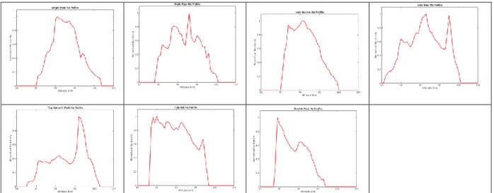
Because of its spatial and temporal evolution, the definition of reference profiles for the Sodium density is not an easy task. Using several data set acquired by T. Pfrommer et al [9], ESO has identified 7 profiles that could be
considered as the “typical” profiles to be expected, and the frequency of occurrence for each of the different shapes is comparable (see ). In the following we will consider either a uniform distribution (for the sake of simplicity) either these 7 profiles perform a first statistical study of the performance of our spot elongation mitigation strategies.
Figure 3 Sodium profiles considered. Those 7 profiles roughly correspond to the main categories of Na profiles, and each
would appear ~15% of the time
3. SPOT ELONGATION AND TRUNCATION: THE PROBLEMATIC
3.1 The simulation toolsThe full analysis presented hereafter has been done using our Matlab End-to-end simulation code OOMAO [10]. The Object Oriented Matlab Adaptive Optics (OOMAO) modelling library is a library of Matlab classes developed for the purpose of facilitating a clear, accessible end-to-end model of AO systems. It is publicly available, open-source code. Objects from the different classes are assembled to perform numerical modelling of an Adaptive Optics system. OOMAO can be seen as an extension of the Matlab language; overloaded Matlab operators are used to propagate the wave-front through the system and to update the status of each object. OOMAO allows the user to generate objects that simulate the following hardware: modal or zonal deformable mirrors, imaging devices with extended exposure capabilities, telescopes with user- defined pupils, and Shack-Hartmann WFSs. Additionally, the library can be used to generate multi- layer atmosphere objects. Asterisms can be defined with any number of guide stars in constellations. OOMAO can implement closed-loop, open-loop and pseudo-open loop systems and has been specifically designed for the modelling of tomographic AO systems. It can also deals with the specific M4 geometry.
3.2 Spatial and temporal content of aberrations induced by truncation
The very first thing that has been done using these profiles was to understand the spatial and temporal content of the aberrations induced by the spot truncation. . Without turbulence we compute the impact of the spot elongation and truncation on the estimated phase. To do so we simulate a full propagation through the system down to the WFS reconstruction (assuming a basic centroiding for the SH-WFS data) and then we analyse the spatial frequency content of the reconstructed phase. Without any truncation, the elongation will only produce Tilt and focus. Because of the truncation (we consider here a 10” FoV sub-aperture) higher order modes are building up. In a full tomographic reconstruction process, several LGS (6 in the HARMONI case) are recombined to tomographically reconstruct the phase in the volume and then project it in a given direction. Tip-tilt and focus will be filtered out during the process (Tip Tilt and Focus will be measured independently on a natural guide star). Hence, without truncation and for high SNR, there will be no impact of spot elongation. In the case of truncated sub-aperture, each WFS will see the “equivalent” static aberrations induced by the truncation, rotated according to the LLT geometry w.r.t. to the LGS pupil. Those aberrations will then be mixed by the tomographic reconstruction and re-projected on-axis by the H-LTAO reconstruction process. Depending on the considered sodium profile it is shown that significant amount of phase (up to a few hundred of nm rms) can be projected onto the 10 (and up to the 100) first Zernike polynomials (see Figure 4).
Figure 4 Simulation of the spot elongation on the LGS WFS and phase reconstruction process through tomography (without
turbulence) to show the wavefront bias induced by the truncation itself. 6 LGS have been simulated. A NGS is considered to measure and compensate for Tip-Tilt and focus terms. The Sodium profile number 4 (one of the most problematic from the truncation point of view) is considered here
4. DEALING WITH SPOT TRUNCTION : REJECTING/WEIGHTING
CORRUPTED MEASUREMENTS
4.1 The cropped WFS case
A first approach to reduce the truncation impact that has been investigated in the frame of the H-LTAO study was to simply reject all the sub-apertures that would be truncated. As a first order approach, we can simply set to 0 a given amount of sub-apertures in the measurements, which could be seen as “pupil cropping”, and look at the impact on the performance. For very redundant system, such a simple but yet very crude approach, is quite efficient since the same part of the pupil is sensed by several Wave-Front Sensors.
Figure 5 reduction of the bias induced by truncation thanks to the cropping of the most elongated part of each SH-WFS
Thanks to the redundancy of the measurements, and the fact that in a side-launch configuration, the elongated spots of one WFS corresponds to the non-elongated spots of another WFS. It is shown that this solution, for the HARMONI configuration and 10”x10” FoV SH-WFS, allows reducing the bias induced by truncation down to a
few tens of nanometres for most of the Sodium profile. For the more complex profiles the gain is less important and typically 150 to 200 nm rms are still present.
As an optimization of this method, it may be possible to weight the measurements in order to only reject the ones along the long axis of the elongation (truncated), while keeping those along the small axis (not truncated). This has been proposed in [11] where the idea is simply to provide a different weight on the measurements according to their elongation. For each spot, the small axis would be kept, while the long axis would be rejected if truncated. This solution is the one studied and optimized hereafter
4.2 The weighted solution – optimization of the reconstruction algorithm 4.2.1 HARMONI control law and MMSE regularization process
The current baseline for the tomographic reconstruction, and the one that has been implemented and used in our simulations, is the POLC + static MMSE [12]. It is important to highlight that all the simulations that has been done were with the same tomographic algorithm as the one that will be implemented in the RTC. This allowed us to fine tune it, and produce realistic performance estimates. In this 2 steps configuration control law, the most critical aspect is the MMSE process which rely on
- Pseudo-open loop data reconstructed from LGS and DM signal
- Tomographic reconstructor which accounts for priors on Cn² profile and noise statistics.
In the case of elongated spots, noise statistics become no-stationary and a sub-aperture by sub-aperture variance map has to be considered with x and y values depending on the elongated size.
Combining a correct noise statistics with accurate turbulence prior will ensure an optimal regularization (and thus optimal reconstruction) process for non-truncated spots and thus will lead to the best possible performance. Because of the truncation, an additional error (bias in our case) is added. The cropping solution (presented above) which simply removes all the sub-aperture affected by truncation (above a given threshold) is equivalent to simply consider an infinite noise weight (both for x and y) for the cropped sub-apertures slopes. In the following we will deal with the spot truncation by simply adding an overweight to the affected sub-aperture signal rather than simply getting rid of them.
Because there is not yet any simple analytical expression to quantify the effect of the truncation we have chosen to simply treat the effect in the noise domain as an “over-elongation”. It basically means that when we compute the noise variance weighed map for the MMSE we simply stretch the equivalent elongation by a given factor. If this factor is larger than 1, we simply assume in the noise variance computation that the spot are more elongated than they truly are. In other word we over-weight the noise impact in the elongation direction and thus we will reduce the impact of the slopes affected by the truncated spot in the reconstruction process.
The very first implementation proposed in this paper is a linear overweight. We are currently investigating quadratic evolution in order to less affect the non-elongated data.
4.2.2 Definition of a downscale system
For the sake of the physical understanding of the truncation problematic and optimization and in order to speed up the simulation process, we have first decided to test the over-regularization process and to quantify its performance on a downscaled version of HARMONI. To
do so, we have considered an 8m telescope case and we have modified the LGS properties in the atmosphere to ensure that we will have the same elongation effects on the telescope sub-aperture (together with the same ratio of elongation between small and large axis). This basically means putting the Sodium layer at 40km altitude rather than 90. All the other AO parameters remain the same: 0.5m sub-aperture pitch, 10x10 pixels per sub-apertures, pixel size 1” (although we also have considered other plate scale in order to study the impact of a larger pixel), LGS spot size (non elongated direction) of 1”. The LGS number will vary from 3 to 12 in order to study the impact of the signal redundancy for dealing with the truncation effect.
Concerning the Sodium profile we first start with a very simple « top hat » structure for the sodium density (width varying from 0 to 30 km) and we will at the end
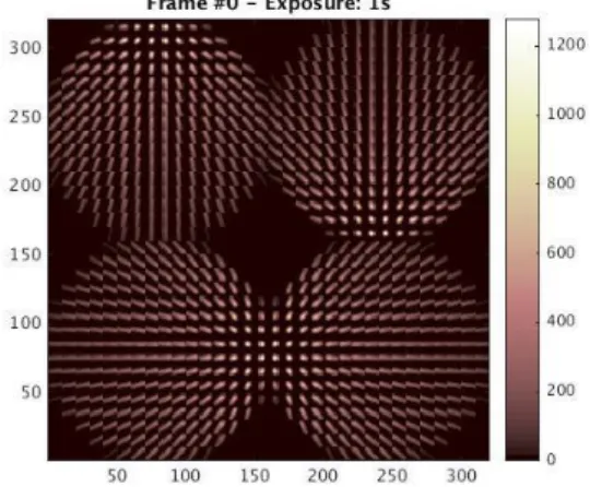
consider the 7 typical profiles presented in Figure 3. In the following, for all the simulations a median 35 layers ESO Cn² profilehas been considered with a 0.65 arcsec seeing @ zenith and a 30° zenith angle. Finally Figure 6 is showing the signal of a 4 LGS system for all the conditions listed above.
Figure 6 Example of a the downsized system for a 4
4.2.3 Flux considerations
Because we are now considering MMSE processes based on regularization aspects and balance between signal and noise, it is fundamental to work in typical flux regime (and with the correct detector characteristics in terms of RON). Concerning the LGS flux, based on several years of OAF operation [13] at Paranal a statistic of photon return has been computed by ESO (see Figure 7). From this information, adding the HARMONI transmission and design (0.5 WFS pitch, 2ms integration time …) we obtain a mean value of 2000 photons/sub-aperture/frame and a pessimistic one of roughly 1000 photons/sub-aperture/frame. The latter one will be considered in the following associated with a 3e- RON detector. 4.2.4 Impact of LGS number
Now, using the downsized version of the ELT-HARMONI LTAO system, let us first study the impact of the number of LGS on the truncation effects. This is done for a classical POLC+MMSE reconstructor with the “classical” regularization. A top hat sodium profile is considered with various width is consider in order to mimic several conditions of spot elongation (from 0 to 25 km width). Figure 8 shows the behavior of the system for various numbers of LGS and various thickness of the Sodium layer.
Performance
Averagephase
Long exp. PSF
Figure 8 [Left] performance of the LTAO system for various number of LGS (3 to 12) and various Sodium Layer thickness.
SR has been computed from the average of 5000 loop iteration. [Middle] average phase over the 5000 loop iterations for 3, 4, 6 and 12 LGS and a 20km Na thickness case. The bias induced by the truncation effect is clearly visible. [Right]
long-exposure PSF computed for the same conditions than the average phases.
First it shows that increasing the number of LGS, i.e. the diversity in the WFS signal definitely helps to directly solve the truncation problem. Whereas 3 and 4 LGS case show a huge performance dependency with the Sodium thickness, increasing the LGS number to 6 and more strongly mitigate this effect. The average phase (over 5000 close loop iterations) clearly shows the bias induced by the truncation. The average phase signature is strongly correlated to the LGS relative position in the pupil. Note that the structure of the average phase will depend on the Sodium profile (in our case it is a top hat profile). It is interesting to note here that the LGS side launch configuration is both a part of the problem and of the solution. Indeed it increases the elongation by a factor 2 (w.r.t the central launch) but it also brings much more diversity in the measurements. The largest elongated data for one LGS are compensated by non (or very small) elongated data coming from the other ones.
4.2.5 Change the WFS orientation
It is obvious that the truncation effects are caused by the ratio FoV / elongated size. In the case of a limited number of pixels and if we want to avoid to consider very large pixel scales (for obvious problem of
linearity and SNR issues), a simple geometric solution to directly increase this ratio is to play with the SH-WFS orientation. Indeed, having the elongation direction in the x (resp. y) axis is the worst possible case. In the HARMONI configuration the LGS geometry is fixed with respect to the WFS, therefore a sensible solution would be, for a given LGS asterism (associated to given laser projector in the pupil) to rotate each WFS in order to ensure that largest elongation always sit in the sub-aperture diagonal. In that case a direct √2 gain in FoV is directly achievable. This is illustrated in Figure 9 where the gain in performance for a rotated SH is clearly demonstrated.
Figure 9 Impact of WFS rotation with respect to the LGS elongation. 4 LGS have been considered here. [Left] SR vs Sodium
thickness for a 0° and 45° orientation. [Right] for a 15km Sodium width, evolutuion of the performance as a function of the WFS orientation.
4.2.6 When the adapted weighted process enter into the game
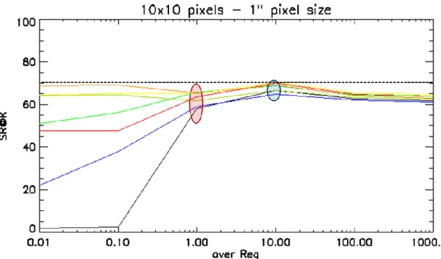
Let us now study the impact of a modification of the weighted map in the MMSE process in order to account for the bias induced by the truncation. To do so we consider the 4 LGS case without any rotation (in order to have strong truncation effects due to the poor WFS signal redundancy). The over weighted (also called over regularization in the figure since what is matter is the ratio between noise and signal which will automatically weighted the ration between Least Square and prior in the MMSE scheme) is evolving from 0.1 to 20.
Figure 10 clearly shows the benefit of having an over-weighted coefficient for the elongated direction in order to account for additional “noise” (in fact bias) brought by the truncation. The non-elongated cases are barely affected and the cases of strong elongation are clearly mitigated. In the case of 15 to 25 = km width, a factor 20 almost completely mitigate the truncation effects.
Of course this over-weighted process is a kind of ad-hoc solution since it does not rely on physical expression of the bias and it could be certainly improved by adding statistically based information on the bias induces by the truncation. This will be the object of further works.
4.2.7 Real profiles
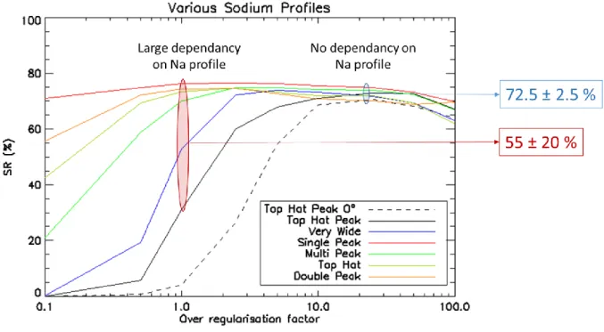
Let us now consider more realistic Sodium profiles as defined in Figure 3. Again, in order to put the emphasis on the truncation effect we have considered here a 4LGS case. The SH-WFS have been rotated with a 45° angle in order to have the largest elongation in the sub-aperture diagonal. The 7 profiles have been processed and we have studied the final performance with respect to over-weighted (called in Figure 11 “over-regularization factor”) coefficient. Figure 11 gathers all the results. For one single profile (the worst one in term of truncation effect) the case of non-rotated SH-WFS has also been added (dashed line in Figure 11).
Figure 11 Performance of a 4 LGS tomographic reconstruction for nominal turbulence condition (as defined by ESO for the
ELT) and for 7 sodium profiles (single peak and very narrow are superimposed). SH-WFS have been rotated so that elongated spot are aligned with sub-apertures diagonals. Performance is plotted w.r.t the over-weighted coefficient (a.k.a.
over-regularisation factor). The specific case of a non-rotated SH is plotted for comparison in the case of the strongest truncated profile.
The Figure shows the strong performance dispersion when a “classical” MMSE law is considered (that is without any over-weighted to account for truncation bias). The performance goes from typically 25% (even less than 5% in the case of non-rotated SH-WFS) in the case of the largest and most structured profile (so called “Top Hat Peak” and “Very wide”) to 75% for the narrowest (“Single Peak”). The addition of a over-weighted coefficient (between 10 and 50, the sensitivity to this value is hopefully quite low) allows to dramatically reduce the performance dispersion and all the profiles have now more or less the same performance 72.5 ± 2.5 % whereas without the over-weighted process the mean performance computed on all the profile was only 50% with more the ± 20 % dispersion!
4.2.8 Real HARMONI simulations
Finally, in order to quantify the real impact on HARMONI, let us consider a full ELT size simulation with all the HARMONI features included in it. The main parameters are recalled hereafter. A 39m Telescope with 0.3 central obstruction is considered. The turbulence profile is the median 35 layers ESO profile with a global seeing at zenith of 0.65 arcsec. A 30° zenith angle is considered. 6 LGS on a regular 35” diameter asterism are used for the high order mode WFS whereas a bright on axis natural guide star is used for Tip-tit and focus sensing (NGS
optimisation is beyond the scope of this study). The LGS spots in the non-elontagated direction are supposed to have 1” FWHM. For LGS wavefront sensing, 6 SH-WFS with 0.5m pitch are considered. Each sub-aperture has 10x10 pixels with a projected size on sky of 1”. The associated detector RON is 3e- and a flux of 1000 photons per sub-aperture and per frame is considered. The centroiding measurement is performed thanks to a classical threshold CoG process. The AO loop embedded a POLC+MMSE control scheme. It runs at 500Hz with a 2 frame delay. For each simulation the same turbulent seeds have been used (so that each result can be directly compare to the other without worrying about convergence issues) and 1000 loop iterations have been considered to compute SR. Finally the 7 typical Sodium profiles are used and performance is estimated for each of them. The results have been plotted in Figure 12.
Figure 12 Performance as a function of the over-weighted coefficient for a full scale ELT case (6 LGS) and the 7 profiles.
Without over-weighted the average SR (on the 7 profiles) is 62% ± 5% with a factor 10 it goes up to 68% ± 2% whereas the non-elongated case is 71%
Figure 12 shows that, as already demonstrated on the downsized case, the over-weighted coefficient helps in reaching the ultimate performance of the tomography while reducing the dispersion of the results due to the various Sodium profiles. In the case of non-elongated spot, the ultimate performance will be 71%. For elongated case and a classical POLC+MMSE control law the final performance is, in average, 62% associated to a dispersion from a Sodium profile to another of 5%. If a 10 over-weighted coefficient is considered, the average performance goes up to 68% with a dispersion of less than 2%. Finally, if we increase the number of pixel in the WFS (from 10x10 to 14x14), without any adjustment of the MMSE coefficient, a 70% ± 1 % is reached. The final results for HARMONI are gathered in table 1.
Table 1 Summary of HARMONI LTAO performance in presence of elongation for several SH-WFS and MMSE control law
configurations
10x10 pixels 10x10pixels - « opt reg » 14x14 pixels No elongation 62 ± 5 % 68 ± 2 % 70 ± 1 % 71%
5. CONCLUSION: TOWARD A BASELINE FOR ELT LGS-ASSISTED
INSTRUMENTS
This paper presents an analysis of the spot elongation problem for Laser assisted tomographic system on the ELT. The problem is described as well as several solutions (both from the opto-mechanical and the control point of view) to deal with it.
A specific solution, using classical SH-WFS has been thoroughly studied. It is based on existing concepts (both from optics and pixel processing point of view) and does not require any specific development. It is therefore
shown that, by just adjusting the WFS orientation and playing with the MMSE weighted noise map, it is possible to dramatically reduce the bias effect induced by the truncation. This will allow us to dramatically reduce the risk associated to this particular effect. It will simplify the requirements on our truth sensor especially in terms of temporal frequency.
From the various study proposed in this paper, a baseline for the HARMONI LGS WFS can be derived
More than 10x10 pixels per sub-aperture. Ideally 14x14 pixels wich corresponds for a 78x78 sub-aperture system to 1100x1100 pixels. This is compatible with the C-MORE camera (see [14])
A Pixel size between 1” – 1.25”. Considering the current AOF measurements of the LGS spot size, 1.25” seems to be a good compromise
A WFS orientation with sub-aperture diagonal in the LGS maximum elongation
The 3 combined items will lead to a “effective” FoV of 24.5” which will be more than sufficient to accommodate any spot elongation produced by the sodium layer structures. It should therefore ensure a bias free and efficient tomographic process.
On top of that, as a risk mitigation aspect and for the sake of robustness, an adapted reconstructed algorithm with a slightly over-weighted of the most elongated sub-aperture. This will be completed by a low frequency truth sensor (working on a very faint natural guide star and coupled with our fast Tip-Tilt Focus sensor) which will measure any LGS slowly variable non-common path aberrations (including any residual aberrations induced by the truncation effects).
Finally, if there is still an issue with the large format detector and only smaller detector (< 800x800) would have been available, the several solutions proposed in this paper could be implemented and combined to further improve the robustness of the system to spot elongation:
- Implement fancy tilted µlenses in order to avoid spot overlap and to maximise the detector fill factor. Spoof concept.
- Increase the spot size up to 2 arcmin together with the increase of the Laser FWHM. The price to pay is here a loss in SNR for ALL the WFS sub-apertures [15]
And for future systems (next generation of Laser assisted tomographic system on the ELT) a change of WFS concepts may be an attractive path to follow. In particular Fourier-Filtered WFS (Pyramid like, Ingot concept ...) seems to be a promising path for dealing with the spot elongation with a minimal number of pixel [16].
ACKNOWLEDGMENTS
This work has been done in the frame of the HARMONI project. The authors would like to warmly thank all the member of the HARMONI team for their contributions. This work has also been partially funded by the WOLF ANR project (ANR-18-CE31-0018-01), the H2020 Opticon program (grant number 730890), and the LABEX FOCUS
REFERENCES
[1] Thatte, N. et al. "The E-ELT first light spectrograph HARMONI: capabilities and modes", Proceedings Volume 9908, Ground-based and Airborne Instrumentation for Astronomy VI; 99081X (2016) https://doi.org/10.1117/12.2230629
[2] Neichel, B. et al. "The adaptive optics modes for HARMONI: from Classical to Laser Assisted Tomographic AO”Proc. SPIE 9909, Adaptive Optics Systems V, 990909 (26 July 2016); https://doi.org/10.1117/12.2231681 [3] Vernet, E. et al. "LGS Na spot elongation and Rayleigh scattering effects on Shack-Hartmann wavefront sensor performances” Proc. SPIE 3762, Adaptive Optics Systems and Technology, (27 September 1999); https://doi.org/10.1117/12.363578
[4] Downing, M. et al. "Update on development of WFS cameras at ESO for the ELT", Proc. SPIE 10703, Adaptive Optics Systems VI, 107031W (10 July 2018); https://doi.org/10.1117/12.2314489
[5] Rigaut, F, Private communication
[6] Neichel, B. et al. "Reconstruction Strategies for GeMS", 1st AO4ELT conference, 02010 (2010)
[7] Gendron, E, "Optical solutions for accommodating ELT LGS wave-front sensing to small format detectors", Proc. SPIE 9909, Adaptive Optics Systems V, 99095Z (27 July 2016); https://doi.org/10.1117/12.2234288 [8] Esposito S, Agapito G, Giordano C et al. "Pyramid wavefront sensing using Laser Guide Star for 8m and ELT class telescopes" Proceedings Vol 9909, Adaptive Optics Systems V; 99096B (2016) https://doi.org/10.1117/12.2234423
[9] Pfrommer, T and Hickson, P., “High-resolution lidar observations of mesospheric sodium and implications for adaptive optics”, Journal of the Optical Society of America A Vol. 27, Issue 11, pp. A97-A105 (2010) https://doi.org/10.1364/JOSAA.27.000A97
[10] Conan, R. and Correia, C. "Object-oriented Matlab adaptive optics toolbox", Proc. SPIE 9148, Adaptive Optics Systems IV, 91486C (7 August 2014); https://doi.org/10.1117/12.2054470
[11] Bechet, C et al., “Optimal reconstruction for closed-loop ground-layer adaptive optics with elongated spots”, Journal of the Optical Society of America A Vol. 27, Issue 11, pp. A1-A8 (2010) https://doi.org/10.1364/JOSAA.27.0000A1
[12] Ono, Y et al., “Estimation with recursive Toeplitz reconstructor structure for large-scale systems”, Journal of the Optical Society of America A Vol. 35, Issue 8, pp. 1330-1345 (2018) https://doi.org/10.1364/JOSAA.35.001330
[13] Oberti, S et al., "The AO in AOF", Proc. SPIE 10703, Adaptive Optics Systems VI, 107031G (10 July 2018); https://doi.org/10.1117/12.2314055
[14] Oberti, S et al. "LGS tomography and spot truncation: tips and tricks ", This conference
[15] Gach J-L et al. "C-MORE: the laser guide star wavefront sensor", This conference, arXiv:1910.00374 [16] Ragazzoni et al. "Extending the pyramid WFS to LGSs: the INGOT WFS”, Proceedings Vol 10703, Adaptive Optics Systems VI; 107033Y (2018) https://doi.org/10.1117/12.2313917


![Figure 8 [Left] performance of the LTAO system for various number of LGS (3 to 12) and various Sodium Layer thickness](https://thumb-eu.123doks.com/thumbv2/123doknet/14769749.590344/8.892.480.778.146.351/figure-performance-various-number-various-sodium-layer-thickness.webp)