Effect of Control Interface Implementation on
Operation of a Multi Degree of Freedom Telerobotic
Arm
MASSACH UTEOF TECHNOLOGY
by
Jul_1
2017
Sherrie Alyssa Hall
M.S., Georgia Institute of Technology (2012)
ARIES
ARCHIVES
Submitted to the Department of Aeronautics and Astronautics
in partial fulfillment of the requirements for the degree of
Doctor of Philosophy
at the
MASSACHUSETTS INSTITUTE OF TECHNOLOGY
June 2017
@
Massachusetts Institute of Technology 2017. All rights reserved.
Signature redacted
Author...
Department of Aeronautics and Astronautics
June 2017
Signature redacted
Certified by...
...
eia Stirling
Assistant Professor
Thesis Supervisor
Signature redacted
Accepted by...
Youssef M. Marzouk
Signature
redacted
Certified by. ...
Jeffrey A. Hoffman
Signature
red acted
Professor of the PracticeC ertified by .... ...
Julie Shah
Effect of Control Interface Implementation on Operation of a
Multi Degree of Freedom Telerobotic Arm
by
Sherrie Alyssa Hall
Submitted to the Department of Aeronautics and Astronautics on June 2017, in partial fulfillment of the
requirements for the degree of Doctor of Philosophy
Abstract
In exploration, scenarios can include a human working along-side - or attached to -a robot. For ex-ample, concepts of M-ars hum-an-robot explor-ation te-ams, or extr-ave- extrave-hicular activity (EVA) on the International Space Station (ISS) with an astronaut fixed to the end of a large robot arm for stability. Robots in these scenarios must be able to be directed in real time to react to environmental unknowns. In this work, use of a fully-wearable gesture system was proposed to provide control of the robot to the human in the field. A wearable gesture interface would allow user mobility in the field, would allow the user full arm range of motion when not in use, and could be built into the user's clothing to avoid requiring them to carry additional equip-ment for robot control. This work used the Canadarm2 as a case study for exploring implementations and input mappings for robot operations with a gesture interface in complex environments. Manual control of the Canadarm2 is difficult, involving a complex twin-joystick interface. Although astronauts on EVA often stand fixed at the end of the robot arm for stability, EVA astronauts cannot control the arm them-selves, instead relying on teleoperation by a second astronaut inside the ISS. A study was conducted with a simulated Canadarm2, comparing three different gesture imple-mentations to the traditional joystick input method. In order to test gesture control mappings of this case, a gesture interface was needed for operation. The wearable gesture system selected used integrated surface electromyography sensors and inertial measurement units to detect arm and hand gestures.Two gesture mappings permitted multiple simultaneous inputs (multi-input), while the third was a single input method. One multi-input method was inspired and aligned with natural human reach while the other divided controls between different segments of the human arm kinematic chain. The single input method exhibited high workload in addition to reduced ef-ficiency as compared to the joystick control group. The gesture mapping inspired
by human motor control showed potential for performance equivalent to traditional
joystick controls after training. The multi-input mapping less aligned with natural motor control showed reduced completion rate for certain tasks and higher overall workload as compared to the joystick interface. Unlike the joystick controls, the
ges-ture interface was limited to one rotational input at a time. To investigate potential performance effects due to such limits on controller degrees of freedom (DOF), a sec-ond study was csec-onducted that locked different DOF in the joystick interface. Four joystick interfaces were compared: full multi-axis (with nominal six DOF), rotation limited (one rotation at a time), translation limited (one translation at a time), and without simultaneous translation/rotation or "non-bimanual." This study found no statistically significant differences in performance or workload between traditional controls and reduced rotational DOF, which was comparable to the gesture interface mapping. For the non-bimanual condition, there was an increase in task time com-bined with decreased multi-rotation, highlighting that non-bimanual operation may have potential in training for rotation efficiency. Two different strategies were ob-served during translation limiting to overcome inability to visually track, align with, and move toward the target simultaneously. This work highlights the importance of multi-input control for complex robotic teleoperation and provides recommenda-tions for the development of input mappings and implementarecommenda-tions of gesture control interfaces, as well as any interfaces that require reduced DOF as compared to the operational environment or system being controlled.
Thesis Supervisor: Leia Stirling Title: Assistant Professor
Acknowledgments
I have been fortunate to have incredible support in making my PhD a reality. First and foremost, I'd like to thank my advisor, Leia Stirling, for taking me on as her first AeroAstro PhD student. It has been my privilege to have her guidance, as we faced each milestone together. Thank you to my committee members: Jeff Hoffman, for giving me the opportunity to study at MIT to begin with and so many opportunities since. To Julie Shah, both for her guidance on my thesis and for becoming one of the best house-masters a student resident could ask for. You all provided advice and helped me learn to navigate the academic world over the past five years, but more importantly, through conversations, dinners, events, and support, you each helped me truly live at MIT.
To my readers, Andy Liu and Chris Assad: Thank you for your support. Andy, thank you for your perspective and guidance. Chris, thank you for your enthusiasm, your constant determination to make sure the BioSleeve project continues, and letting me be a part of the incredible research opportunities this project has involved. On that note - thank you to the entire BioSleeve team at JPL. You have all be great to work and fly with. Thank you also to Clementine Mitchel, one dedicated UROP who worked through a seemingly endless de-bugging effort, hardware issues, and even learning to use a needle and thread.
The Man Vehicle Lab is an amazing group of people, and I cannot imagine a better lab to work with. From my first week and the 50th anniversary, to Thanksgiving, to every memorable Friday, the camaraderie and kindness of this lab is outstanding. I am lucky to have had such a supportive environment as a graduate student. Thank you to Dava Newman, Chuck Oman, Larry Young, Alan Natapoff, and Liz Zotos for all you do to keep the MVL going. Outside of lab, thank you to everyone from Sidney-Pacific the "best graduate residence in the universe!" as Roger would say. My friends and time at SP made it a second home. One where food, laughter, a cup of tea, and a board game were never far away. I also want to thank everyone at Georgia Tech, especially HPEPL, and from the Girl Scouts of Northeast Georgia, without
whom I would never have made it so far.
Finally, thank you to my friends and family. You've supported me through this journey, and seen me through every struggle and success. You've been there with phone calls, baked goods, and encouragement. Thank you to my mom, for always believing I'd get this far. Thank you Jack, my best friend, my partner in all things. Thank you for putting up with late nights, for providing coffee, and for reminding me to take a break and see a movie or play a game, even at the busiest of times.
This work was supported by Jet Propulsion Lab Award 1516097. The SSRMS sim-ulator was developed with support from NASA Contract NCC9-58, NSBRI SA1301, NSBRI SA001, and NSBRI NBPF02001. All study protocols were approved in ad-vance by the MIT Committee on the Use of Humans as Experimental Subjects.
Contents
1 Introduction
1.1 M otivation . . . .
1.2 Previous Literature . . . . 1.2.1 SSRMS Operation . . . .
1.2.2 Creating Intuitive Interfaces . .
1.2.3 Multi-DOF Interfaces in Six DO
1.2.4 Gesture Control . . . .
1.3 Case Study Experimental Environment
1.4 The SSRMS Simulator . . . . 1.5 The JPL BioSleeve . . . . 1.6 Thesis Structure . . . . 2 Project Development 2.1 IMU Integration . . . . 2.1.1 IMU Characterization... 2.2 Gesture Mappings . . . . 2.2.1 Single Input . . . . 2.2.2 Multiple Inputs . . . .
2.3 Interface Development Study . . . .
2.3.1 Motivation and Hypotheses . .
2.3.2 M ethods . . . . 2.3.3 Results . . . . 2.3.4 Discussion of Results . . . . Environments 11 11 14 14 16 17 21 28 29 33 35 39 39 42 45 47 49 51 51 52 59 62
3 Investigation of Gesture Control Mappings
3.1 Motivation and Hypotheses . . . .
3.2 M ethods . . . . 3.2.1 Participants . . . . 3.2.2 Experimental Tasks . . . . 3.2.3 Data Processing . . . . 3.2.4 Experimental Procedure . . . . 3.2.5 Statistical Analysis . . . . 3.3 R esults . . . .
3.3.1 Effect of Input Method on Task Time . . . .
3.3.2 Effect of Input Method on Task Success . . . .
3.3.3 Effect of Input Method on Workload . . . .
3.3.4 Usage of Multiple Axes . . . . 3.4 Discussion of Results . . . .
4 Effects from Limiting Interface Degrees of Freedom
4.1 Motivation and Hypotheses . . . .
4.2 M ethods . . . . 4.2.1 Participants . . . . 4.2.2 Test Environment . . . . 4.2.3 Test Conditions . . . . 4.2.4 Data Collection and Analysis . . . .
4.2.5 Protocol . . . . 4.2.6 Statistical Analysis . . . . 4.3 R esults . . . . 4.4 D iscussion . . . .
5 Conclusions
A Appendix A: Experiment Training Slides
67 67 68 68 68 68 69 71 72 72 74 75 77 78 83 83 85 85 86 86 87 88 90 92 96 103 117
A.1 SSRMS Basic Training for Hardware Development and Gesture Studies
(Chapters 2 and 3) . . . . 117
A.2 Task Training for Hardware Development Study (Chapter 2) . . . . . 124
A.3 Task Training for Gesture Study (Chapter 3) . . . . 127
A.4 Task Training for Degrees of Freedom Study (Chapter 4) . . . . 129
B Appendix B: Pre-Experiment Participant Background Questionnaire 137 C Appendix C: Additional Gesture Study Materials C.1 Joystick Input Handout . . . . C.2 Single Input Gesture Handout . . . . C.3 Endpoint Control Gesture Handout . . . .. C.4 Coupled Input Gesture Handout . . . . C.5 Handout Illustrating Translation Command "Box" trol and Coupled Input . . . . C.6 Training Checklist . . . . C.7 Verbal Task Instructions . . . . C.7.1 Path Following Training . . . . C.7.2 Track and Capture Training . . . . C.7.3 Fly-to and Grapple Training . . . . C.7.4 Path Following Evaluation . . . . C.7.5 Track and Capture Evaluation . . . . C.7.6 Fly-to and Grapple Evaluation . . . . 139 139 140 141 142 for Endpoint Con-. Con-. Con-. Con-. Con-. Con-. Con-. Con-. Con-. Con-. Con-. 143 . . . . 143 . . . . 144 . . . . 144 . . . . 144 . . . . 144 . . . . 144 . . . . 145 . . . . 145
D Appendix D: Task Selection Effects in DOF Study D.1 Effect of Drift Type: Results . . . . D.2 Effect of Drift Type: Discussion . . . .
147
148 149
Chapter 1
Introduction
1.1
Motivation
Exploration scenarios with human-robot collaboration include operations where a robot and human move alongside each other through an environment. This includes scenarios such as concepts for human-rover teaming on Mars surface exploration mis-sions, extravehicular operations on the International Space Station (ISS) with an astronaut fixed to the end of a large robot arm for stability, or earth-based mili-tary and law enforcement applications with teams aided by reconnaissance rovers. In such situations, the solution to directing robot movements in reaction to environmen-tal unknowns in real time, is to have a dedicated human teleoperator control robot movement. For space exploration applications, having a dedicated remote operator is not ideal. An Earth-bound operator may be subject to time delay, depending on the distance of the mission from Earth. Using a crew-member to operate from a nearby location such as on the ISS or in a habitat on Mars requires that crew-member to be dedicated to robot teleoperation and monitoring for the duration of robot operations, preventing them from completing other tasks. With a small crew on a spaceflight mission, crew time is a valuable, limited resource. The logical alternative would be to allow humans working alongside the robot to assume control as needed. These scenar-ios all involve human collaborators who must already carry equipment, be completely mobile, and have hands free for other uses for most of their mission.
In order to accommodate these needs, the concept of fully-wearable gesture control was proposed. Such a system would be worn on a user's arm, either integrated into or worn under the operator's clothing (or spacesuit). With gesture control, the human arm and hand become the interface, requiring no additional hand-held or bulky equipment. In this concept, the ISS robot arm may be left stationary, or a recon rover given automation to follow a human team for an extended time. However, if the EVA astronaut needs to change position, or a ground team needs to direct the rover to a point ahead, the human collaborator could then turn on a control system, and direct the robot as needed. Inputs for robot motion would become simple hand gestures, such as pointing the, hand or rotating the wrist in the direction the robot needs to move.
Although gesture interface hardware and software development is critical to cre-ation of a functional, reliable system, implementcre-ation of gesture commands must also be considered. Even if ideal sensors and robust processing allowed an interface per-fect gesture recognition, without a mapping of gestures to command inputs that an operator may learn and use with proficiency, the system as a whole would be rendered ineffective. Determination of strategies for intuitive mappings became a main focus for this work.
There are many robotic operation scenarios that require function and real-time planning in large or unconstrained environments, including reconnaissance operations and space robotics. Use of a fully-wearable gesture control system is well suited to human-robot or human-computer interaction scenarios where users are mobile, must have full range of motion for their hands when not operating the robot, or have limited availability for carrying additional equipment. Operation of the International Space Station (ISS) robotic arm (also called the Space Station Remote Manipulator System (SSRMS) or Canadarm2) to support astronauts on Extravehicular Activity (EVA) aligns with cases well-suited for gesture control. The SSRMS requires robotic movements through all three axes in space with operation through a range of small or large-scale tasks.
gestures to command inputs for a wearable gesture control interface and implications of broader interface design choices, namely degrees of freedom (DOF) included in a control mechanism. In a broad sense, this meant exploring the relationships be-tween a control interface, the system being operated, and operation in a complex environment, in order to improve future interface design for such environments. A "complex" environment here refers to a machine's physical operating location which is unconstrained or large scale. Increased environment DOF also contribute to envi-ronmental complexity. The DOF of an environment are defined.,here separately from the DOF of a robot or the DOF of a control interface. While robot DOF refer to the physical degrees of freedom in the robotic system, interface DOF refer to the total simultaneous inputs feasible for that controller, and environment DOF refer to the spatial degrees of freedom for the axes relevant to the operational space. Thus, as an example, if a simple ground rover were maneuvered across a plane, there would be a two-dimensional, three DOF environment (two translation directions and one rota-tion direcrota-tion are possible). However, in the case of a flying vehicle or robotic arm with vertical motion through three-dimensional space, there would be a six DOF en-vironment. Meanwhile, if an interface allowed inputs in three translational directions and one rotational direction at a time, that would represent a four DOF interface, regardless of the robot being operated or its environment.
To investigate different mappings of gesture to command in a fully-wearable inter-face, a system was adapted using a combination of surface electromyography (sEMG) sensors and inertial measurement units (IMUs) to allow multiple inputs at once. With sEMG sensors alone, only one input could be made at a time. IMU integration en-abled multi-input operations. Over the course of multi-input mapping development and study, translation inputs were selected to be driven by IMU data while rotation inputs were predominantly by sEMG control. Mapping translation and rotation in this manner was done in order to match operator gestures with an anticipated men-tal model of end-effector motion, in an effort to make the mappings more intuitive. It was acknowledged that due to the nature of sEMG signal processing, any subset of commands mapped to the sEMG portion of the interface would preclude those
commands from being input at the same time, thus reducing the overall interface DOE. To both better characterize the gesture mappings being investigated and in-form future interface/input mapping designs, further investigation would be required to determine how removal of different degrees of freedom from the interface would impact operation in a six DOF environment. Furthermore, understanding the im-pact on operations of using different DOF limited controller conditions would have an impact on robotic interface design beyond space and gesture applications.
Thus, this work sought to explore the following overarching research problems: Problem 1: Can wearable gesture control be used as an effective control interface for a complex robotic arm system?
Problem 2: Does a multi-input gesture control mapping provide enhanced perfor-mance over traditional single-input gesture control strategy in operation of a high-complexity robotic system?
Problem 3: How are performance, workload, and technique affected by the available degrees of freedom in a control interface?
1.2
Previous Literature
1.2.1
SSRMS Operation
The SSRMS, or Canadarm2, is a 7-degree-of-freedom manipulator system designed to reach as many regions of the International Space Station as possible [691. Although the joint design is meant to mimic a human arm, with a "shoulder," "elbow," and "wrist," control of the robotic arm is a notoriously difficult challenge. The arm may be operated aboard the ISS from one of two Robotic Work Stations (RWSs), or can take commands from ground controllers. Whether controlled from ground or on station, an SSRMS operator relies on three display screens with views from different cameras outside station and on the Candarm2 itself to guide its direction. The operator must choose camera positions wisely to provide suitable visual feedback, and thus avoid singularities in the manipulator system and collisions [61]. Commands input by the
operator control the manipulator arm at the end-effector, or "hand" segment. The control interface for the SSRMS was designed with two joystick hand-controllers, with three translation DOF controlled by the left hand joystick, and three rotation DOF controlled by the right hand joystick [13].
An important factor for ensuring successful SSRMS operation is that the user maintain awareness of the robot arm's orientation and surroundings. The Candarm2 allows selection of different coordinate systems for controlling the end effector, which changes the mapping between joystick inputs and end-effector motion. Options for operational reference frame, or Command Frame, include axes centered at and moving with the end-effector (referred to here as "internal"), axes fixed with respect to the center of the ISS truss (referred to here as "external"), and others fixed to a point of preference such as payloads attached to the manipulator, points along station, or a point in space. The dynamics and position of the arm is calculated within the SSRMS computer using additional joint frames [13]. One attempt to improve operator awareness during missions was to provide 3D animations of potential robotic maneuvers for controllers to use during training 1611. Such animations would allow operators to view arm motion from varying angles prior to taking the controls, and have a better understanding of arm joint motion during different movements, although the result of implementing this system is yet to be determined. Other attempts to mitigate risk of collisions due to the challenging nature of SSRMS operations have included extensive operator training pre-flight on generic skills such as basic arm navigation and planning [181. This has included instruction using the "Dynamic Onboard Ubiquitous Graphics" (DOUG) system, a three-dimensional desktop tool that allows astronauts to view the full station, added objects, and Canadarm2 from any angle in a virtual environment
11].
Additionally, long-term, detailed planning of robotic arm movements have been used for specific missions, with SSRMS operation essentially choreographed and rehearsed by the crew. The Canadian Space Agency(CSA) and NASA began pre-mission planning of ISS assemble missions two years in
advance, detailing explicit manipulator motions with adjustments based on operator input up-to and through real-time support during operations
1491.
As a whole, theCanadarm2 represents a high DOF robotic system operated in a six DOF, large-scale complex environment, and requiring real-time control capability - a system of the kind that was of interest for this research.
1.2.2
Creating Intuitive Interfaces
As discussed previously, one of the main goals for this study was to understand how interface design decisions affect system performance and workload, with the goal of enabling more intuitive interface designs in the future. An intuitive control interface is both easy for a new user to learn quickly and responds to command inputs in an expected way. Once implemented, such a design should reduce training time for a system, and ideally reduce cognitive and/or physical workload. Some define such intuitive interaction as a "subconscious application of prior knowledge" [371. This
requires matching the system's responses to the operator's idea of what is happening (their mental model of the system), or designing with user expectation in mind.
A long-time proponent of user-centered design, Donald Norman is an expert on
human interaction and cognitive perception of products. In his extensive writing, he frequently evaluates the concept of "human error" and provides a simple theory: while error is often blamed on the ability or alertness of the user, they are not the cause of the problem. The design of the system is flawed in a way that leads to errors, or more specifically slips and mistakes [60], by not engaging the human user in an appropriate way [51, 521. Many interface designs considered "intuitive" are based on previous systems. In his work, Raskin considers intuitive to mean familiar [59]. He points out that just because a system is based on an interface that came before and is easy to learn does not make it effective for its purpose. However, an interface without any basis in the familiar can be frustrating.
In discussing design of gesture-based systems, Norman points out that poor design can still lead to problems when using natural-seeming motions as an input
153].
One highlighted example is the Wii hand-held controller used in a bowling game, which people tend to let go of when swinging their arm as if throwing the ball. This corresponded to a real environment, where people would release their hands bowling.Nintendo tried instructing players to wear a wrist strap to keep the controller from becoming a missile, but this has merely made Norman's case that effective interfaces must include obvious hints and signs, called signifiers, that make intended use seem simple. Additional cues may be used if not all signifiers are apparent, however adding extra instructions will not fix design [531. An effective gesture interface design would still have some learning curve, but an explicit conceptual model is key to successful design implementation. Even still, interface designs must include options to reverse actions should the user find that they moved in an unexpected way that the system was still able to interpret, creating an unintended state
153,
66].1.2.3
Multi-DOF Interfaces in Six DOF Environments
As defined in Section 1.1, it is possible to have a human-machine system in which a machine or robot with multiple degrees of freedom is designed to move through a six DOF environment in a three dimensional way, yet the human interface may have degrees of freedom different from the machine being operated, the environment, or both. Historically, designs for multi-DOF interfaces have reflected either the machine or environment DOE.
Early Design for Multiple DOF
As three dimensional graphics became practical in computer systems during the late
1990s, research into user-driven design of interfaces for maneuvering through three
dimensional environments had virtual applications (e.g. simulator environments, 3D graphic arts software) not driven by the mechanical dynamics of a system (e.g. an aircraft) [78]. Interfaces with input decomposed into individual DOF controllers via buttons, sliders, or their virtual counterparts, each operating a single DOF, may be a simple design for mapping inputs to a system's output motion and allow mapping of a two DOF interface such as a computer mouse to six DOF applications. However, a user would be required to coordinate in time the individual activation of each DOF, and as observed by Zhai [78], if a user "has to time-multiplex between the separate
degrees of freedom, it is not possible to form a coordinated movement in the six DOF space." Furthermore, dividing rotational DOF control into individual axes controls without any form of integrated interface or visual aid was found to be unwise [78, 54J. Humans have been found to be limited in their ability to interpret orientation as a series of individual axes rotations [54] making operation with such decomposed axis controls exceedingly difficult.
Interfaces explored for six DOF virtual environments with computer graphics ap-plications included an array of devices such as hand held "3D Ball" or hand-held trackers one moved freely through the air [32J, attempts at computer mice that may be "pivoted" on 'their edges to add DOF, roller mice allowing vertical input (the modern scroll wheel), rate-controlled spheres with elastic suspension allowing force-feedback, virtual "3D" pen devices, and "Flying Mice" interfaces similar to the "3D Ball" but shaped for the hand and allowing integrated buttons [781. These interfaces had differences in terms of having position control, rate control, or the presence of force-feedback, but all were fundamentally six DOF interfaces being designed to map to a six DOF environment, or three DOF interfaces in the case where the environment called for translational movements only. In studying the strengths and weaknesses of such devices, Zhai [79 compared user coordination with the same single-handed six DOF input device adapted as either a position or rate controlled interface, ask-ing participants to move a tetrahedron cursor to a target of the same shape in a three dimensional virtual environment as quickly as possible. Operation with a po-sition control device following a master-slave style input (i.e. where system motion is meant to precisely mimic the motion of the input device) resulted in faster task times. However, coordination, measured by directness and speed of trajectory, was higher with the elastic rate control device [79].
In six DOF telerobotics applications such as the original Candarm or remote handling in hazardous environments, King [40], Fischer [221, and Zhai [781 each proposed or recommended variations on one-handed six DOF devices with rate control such as haptic controllers, joysticks, or suspended ball devices as potential practical interfaces. Fischer [221 argued the importance of single-handed interfaces as a critical
design choice, allowing operators to maintain a free hand for secondary tasks. In design of the original Canadarm interface, several single-handed options were explored [40, 451 and a single-handed joystick-style six DOF interface was recommended by those tasked with interface review [481. However, the decision to use the dual-joystick interface still in place on the ISS ultimately depended on a combination of factors, such as reliability, cost, weight, and the preferences of astronauts who favored the the two-joystick system due to its similarity to past flight interfaces with which they were familiar. [471.
Although information on operation with interfaces with reduced DOF relative to both robot and environment is lacking, effects have been observed isolating or restrict-ing DOF for trainrestrict-ing purposes. In part task trainrestrict-ing, a complex task is broken down into different elements, which are taught individually and then brought back together to train the full task
141,
741. Different strategies include segmentation (breaking the whole task into a series of sub-tasks, typically by temporal division), simplification (adjusting task characteristics to make easier, training versions), and fractionation (teaching one control element at a time) [74, 731. Fractionation is most similar to DOF limiting as defined here. As an example, fractionation for a task involving pitch and roll might involve isolating pitch control on an interface and providing instruc-tion on that alone, then isolating roll similarly [74]. Unlike fracinstruc-tionainstruc-tion, in which the training tasks with isolated DOF would only require control of the corresponding input, operations using a controller with reduced rotational DOF would involve a full task (e.g., requiring consideration of both pitch and roll) but the interface would never allow use of multiple rotation inputs simultaneously. Within part task training studies, fractionation was actually found to be the least effective of the three main strategies174,
73] with early work recommending against further use or practicalinvestigation
1741.
For tasks involving bimanual operations, part task training which divides the task into operations with one hand at a time do not contribute to biman-ual whole-task performance [411. Research of bimanbiman-ual tasks using simple tapping or opening motions have shown that a person must perceive the two-handed motions as one, single task or operation in order to succeed [41, 251, making part task trainingwith division into unimanual components impractical. Within training research, a related strategy which may more closely align with effects of limiting interface DOF is a technique which: became known as "variable-priority training" (VPT) [29, 30J. In VPT, different aspects of the task are emphasized or de-emphasized so the user can focus on specific elements, but the whole task remains intact. The emphasized elements show improved performance which carries over to whole-task performance 1101.
Examples on Earth
In surgical robotics, there are robotic arms with a wide range of DOF. Surgical robotic arms with 4 DOF (utilizing two-DOF shoulder and two-DOF elbow joints) have used master-slave style interfaces, for which robot motion is meant to mimic the operator's hand placement and orientation [771. With the robot endpoint controlled
by such devices, the interface provides a feeling of 6 DOF interface control for the
surgeon. Higher DOF surgical arms may have seven DOF or more [5, 671, and
are often controlled via master-slave type haptic manipulators such as hand-held "stylus" devices, hand-held tools, or even arm exoskeleton systems [671. With these interfaces, the six DOF motion controls may be accompanied by integrated triggers or other single-action forms of input used to command robotic actions in additional DOF (beyond six) such as pinching or grasping
151.
In construction, backhoes represent four DOF arm-like systems in which both traditional control schemes use four DOF interfaces to maneuver through three di-mensional (six DOF) space. Traditional four DOF interfaces include dual two DOF joysticks [36] and systems with a three DOF joystick to control the bucket accom-panied by a spin (arm yaw) controller [331. Proposed experimental interfaces use single-handed six DOF haptic devices, typically following a master-slave scheme, thus matching the interface DOF to the environment DOF [361. Crane operation involves a variety of control systems, typically using a combination of joystick and lever, but-ton, or foot controls
1551.
Depending on design, the crane itself my have three or four DOF, while traditional interfaces vary between one and four DOF dependingon the combination of control devices integrated into the interfaces (e.g. a pendant with buttons only, vs. an interface with a two DOF joystick combined with button controls). Crane operation is made more difficult because systems are traditionally controlled either joint-by-joint or at the overhead point supporting the hook, rather than having the operator commands control motion at the payload location, which is more intuitive
1551.
Peng1551
proposed several alternative interfaces for crane operation, all of which were variations on three DOF position tracking of the control device itself, disregarding orientation, once again matching the DOF of the interface to that of the mechanical system itself.1.2.4
Gesture Control
Gesture control is the use of human movements and positions to interact with com-puter or robotic systems. The idea of gesture control has been a pervasive concept in technology development partially because gestures are among the most expressive and natural forms of human communication [71, 8]. However, even with a system available that can readily interpret human motion, the problem still remains of deter-mining how to map inputs to commands. Natural gestures can take on very different appearances or meanings depending on context. Separate definitions of gesture to command mappings may be better suited for different applications, cultures, or op-erational circumstances [71].
Current Gesture Control Methods
Before defining any potential mappings for a gesture control system, it is impor-tant to know and understand how current gesture methods are being implemented. This includes strategies for mapping limb motion to interface commands and how such strategies are employed in different technologies. There are a variety of gesture interface technologies available today, from vision-based systems like the Microsoft Kinect, to hand-held manipulators such as the Wii-mote or surgical robotics devices, and wearable technologies including surface electromyography (EMG) sensors and
inertial measurement units. Across industry and hardware types, gesture systems tend to be implemented in two ways: a master-slave paradigm, or single input using one-at-a-time commands.
Master Slave Paradigm In the "master-slave" paradigm, user motions are
imi-tated by robot or virtual system that is being actuated. This method tends to be a popular approach in development of telerobotic systems designed to perform a task similar to a human limb. The appeal in this tactic is self-evident: if you need to move a remote robotic arm or hand, moving your own to control the robot seems like it would make operation very intuitive and easy to learn. In commercial applications such as the video game industry, gesture recognition systems like the Microsoft Kinect and Leap Motion controller have been implemented in master-slave operations. These readily available systems use a combination of stereo cameras Infrared (IR) sensors, and IR light projection onto a user to resolve a moving person [26, 6]. Challenges of these types of systems include discerning a limited array of gestures or difficulty resolving the user from background clutter. Despite these challenges, Bassily et al.
[6], were able to use the Leap system for master-slave control of a six DOF robotic
arm, having the robot mimic basic hand movements and pinching motions.
For most master-slave interfaces, systems are specifically designed to operate in
highly constrained environments such as a physically confined volume (on the order
of human reach or smaller) [67, 77, 5, 21]. Other environmental constraints can
consist of operation along defined pre-constrained paths with no adaptation [21, or designed specifically toward imitation of human arm motion and function for use in such applications as remote handling of objects [20, 21, 15, 50]. Some practical systems involve a combination of such environmental restriction, which aid in their reliability for such tasks including remote surgery 167].
The master-slave strategy has been the control approach for most surgical robots to date - a manipulator arm at the surgical site follows the motion of a surgeon's hand direction, scaled down to match the dimensions of the site and required precision of the task. The manipulator arms on surgical robots often have six or seven degrees of
freedom [67, 771. In nearly all designs, the operator input is provided with some kind of tangible interface for the hand to grasp, rather than a visual information capturing method such as those mentioned above. These include surgical systems such as the PHANTOM, da Vinci, and CAST devices [67]. The hand-held grip for these systems is generally attached to the robotic workstation, meaning the control mechanisms have a mechanically confined volume as the input workspace.
This approach leads to interesting challenges especially at the boundary of the input workspace. When a surgeon reaches the edge of the workspace for their hand and still has further to move a robotic arm, they must brake the system in order to reset the hand-held controller at the other end of the interface area, then remove braking to continue motion. Another frequent challenge is the mismatch between human hand motion and the kinematics of the manipulator. For example, the da Vinci was designed for small-scale cardiac surgeries, and as a result doctors have difficulty using the device for larger scale abdominal surgeries, with large arc motions causing collisions of the manipulator arms [5].
Inspired by efforts to improve human-robot interaction for telerobotics in haz-ardous locations, research has been conducted to improve master-slave robotics based on, essentially, human intuition. By first having a person mimic what motions they think a robot arm is making, Pierce et al. [581 were able to record discrepancies in
human and robot motion. Subjects imitated planar arm motions of a virtual PR2 humanoid robot, while subject motion was recorded using a Vicon motion capture system. The discrepancies indicate a difference between actual robotic motion and the motion a person perceives as the command they send when using master-slave motion control. These findings are consistent with those of another study which used motion capture human-tracking to validate a master-slave robotic trajectory control method [44]. Lin
144]
found that when the robot tried to exactly follow human arm motion, the mechanical differences between the two resulted in a different endpoint trajectory than was input. Both studies confirm the difficulty of producing intended positional output in master-slave robot-human relationships, which counteracts the ease-of-use they were intended to create.Single Input Paradigm Direct inputs in which separate actions or positions each
trigger one command have an advantage over master-slave systems in that they may be applied to a wide variety of systems without concern for matching human arm kinematics. This technique has grown popular in the video game industry, particularly for systems that use hand-held motion controllers. Devices such as the Nintendo Wii and PlayStation controllers provide six DOF in control inputs, and shake to provide the user with haptic feedback [56]. These systems are now readily available and,
depending on the mapping employed, can be used as an intuitive interface for human-computer interaction
18].
Though there may have been problem cases such as Wii bowling, in single-input style implementations most of Wii sports, Kinect games, and user-developed Kinect content have been acknowledged for success with strong user reviews. However, these systems use an external optical sensor combined with an internal accelerometer to track the motion of the remote [6], and can only track dynamic motions of the remote itself. There is no actual tracking of hand or arm, and the system cannot detect more refined movements like hand position [71]. In addition to relying on an external sensor, this limits the number of discernible gestures that may be used as commands. In a complex system like the SSRMS, over a dozen motion commands would be required simply to operate in six DOF.Systems based on electromyography (EMG) sensors distinguish hand gestures from muscle activation patterns in the arm. EMG systems which use the single-input approach to computer interaction, such as the Myo armband and the Jet Propulsion Laboratory (JPL) BioSleeve
175],
have the advantage of being able to distinguish static hand gestures made with both the fingers and wrist posture. The Thalmic Labs Myo168]
system is a crowd-sourced commercial effort developing a wearable universal remote control. Myo system accuracy has not been published at this time. With a combination of eight surface EMG (sEMG) sensors and two inertial measurement units (IMUs) arranged uniformly in a single band on the forearm, the Myo will let users make specific motions or hand positions as signals to turn on lights, change the page on e-readers, operate RC vehicles, or otherwise act as a universal remote. Therobotics [4]. One of the limits in using sEMGs is that an EMG based system can only reliably detect a finite number of hand and arm positions before the signals become too similar and two or more gestures become difficult to distinguish from one another. This shall be explored further in the following section on wearable systems.
Systems that attempt to provide a more dynamic sense of control by using hand motions as a kind of three dimensional computer mouse still follow this single input paradigm. These have been seen in Microsoft Kinect systems [261, and 3D CAVE virtual environments which leverage motion capture to track human gestures. These systems still only carry out one action at a time, but have an expanded range of command inputs, as they capture both dynamic and static gestures. Additionally, since these systems consist of external sensors examining gestures within a space of view, they often incorporate synchronous gestures made with two hands 126].
Operation of the SSRMS for complex tasks relies heavily on being able to direct motion along multiple axes at once. This means operation through direct input of a single command at a time is unlikely to provide adequate operational performance. The robotic arm has kinematics different from that of a human arm, which makes any attempts at a master-slave system of control highly unlikely to function as desired and impractical. Alternate systems of gesture mapping beyond master-slave and single input for SSRMS commands must be considered if a practical, wearable gesture interface is to be a reality.
Wearable Systems
For an SSRMS gesture system, there is specific interest in developing a fully wearable control interface that may one day be integrated into a spacesuit, in order to allow control while on EVA. Wearable tracking systems do not require any external cam-era for sensing and, once made wireless, free the user from having a fixed opcam-erating volume. Data gloves are a technology worn on the hand, and have great potential in ability to provide information on orientation and motion of hand and fingers
142].
Unfortunately, in order to measure any arm motion or orientation parameters, these systems require connection to additional arm sensor systems or exoskeletons. Thecombination can lead to arm fatigue from use that leads to sluggish "gorilla arms"
[56] due to the weight of the added structure. As observed by Wachs et. al
1711,
data gloves are able to record finger joint adduction and abduction angles with pre-cision, but such finger movement is difficult in a stiff space-suit glove. The restricted movements of fingers within a space-suit represent the greatest obstacle toward use of such a system in EVA applications.
As mentioned previously, EMG sensor arrays may be used to distinguish gestures involving both wrist postures and finger positions. EMGs alone have been used in several studies as an effective means of controlling robotic arms in 3D space [3, 4]. Artemiadis and Kyriakopoulos [3] attempted to feed real-time EMG data from subject arm motion through a computer model and have robotic arm movement correspond precisely to human joint motions. Focusing on shoulder and elbow joints, they were able to achieve robotic manipulation in 2 DOF accurate to 2cm2
variance.
A frequent challenge in use of sEMG technology is collection and accurate
process-ing of signals from the sEMGs themselves. This impacts the ability of such systems to reliably distinguish similar hand positions, or recognize large numbers of gestures. While roughly 26 different hand positions have been recorded on the JPL BioSleeve system, a maximum of 20 gestures have been independently discernible in a single set, and up to 14 have been used in robotic applications [4, 75, 76]. The Myo arm-band has a built in set of five gestures, and encourages developers to try adding their own. However, of the five presets, three of the hand positions are frequently confused when a user attempts to make commands 168]. One option to improve data collec-tion is to improve sensor-skin contact through techniques like embedding sensors in a shape-forming material that conforms to the skin
1391.
Using sEMGs in concert with other sensors expands gesture recognition capabili-ties to include arm orientation and enhance interface performance. Combining EMGs with an accelerometer has been shown as an effective means of control in video game design with single input control [801. Another option would be to use inertial mea-surement units (IMUs) to measure both linear acceleration and angular velocity to supplement the EMG sensor information (as proposed by Wolf et al. and Assad et
al. [75, 4]), enabling use of novel control mappings with multiple inputs at once.
Control of Human Arm Motion by the Central Nervous System
One possible path for developing new mapping schemes for gesture control of robotic
systems, such as the SSRMS, is to investigate how humans naturally move their own arms and hands. While it is preferred to create a mapping that relies on directional commands rather than a master-slave type paradigm, using input gestures that are inspired by human motor control during reach may lead to a more usable interface. Thus, understanding the central nervous system's control of human arm motion and human perception of reach can inform the creation of future gesture mappings.
In normal, voluntary human motion, signals are sent from the brain through alpha motor neurons to relevant muscle groups, which contract to create movement in a limb. Experimental studies of human reach and grasping have shown repeatedly that arm motion from point to point in a healthy adult population is smooth, tending to follow straight or curved paths with a single, maximal peak in velocity
135,
23, 28].Different theories have been explored to explain what type of control mechanism the nervous system uses to direct movement.
According to dynamic optimization theory, movement is determined by minimiza-tion of an objective funcminimiza-tion [241. Some hold that the objective funcminimiza-tion is designed to reach the target with minimal energy expenditure balanced with time efficiency. In contrast, others have suggested motor function resembles a kinematic model that minimizes jerk [24, 351, which can work well for planar motions but suffer break-downs when 3D motion (vertical plane motion) is introduced. The equilibrium point hypothesis follows the concept that reaching motion is led by the hand [9]. During reach, the arm trajectory would follow a path made up from a series of equilibrium points, or points at which opposing muscles (activated in tandem) exert force such that the sum are in equilibrium [34]. Reaching motion has been shown to follow calculated equilibrium trajectories closely for simple movements [23]. What the ex-periments supporting the equilibrium point theory have indicated are that human reach is not directed by the determination of joint forces positioning each consecutive
limb segment, but is directed by the shifting motion of the hand reference frame f23J. Each model of motion, be it optimization of a control function or follow the equilibrium point hypothesis, has different real-world conditions for which it breaks down, but equally has different cases for which it is accurate. More than likely, the true control method used in the human nervous system resembles a model combining elements of these theories. For the models above, a person is able to hit their target of reach regardless of unusual conditions requiring adaptation (such as reach during rotation or in microgravity). However, in reality we know that people with intact motor control can miss the point being reached for in various circumstances. Theories on adaptation indicate that people develop a new internal model for motor control under new force conditions
138,
641. For implementation of a gesture interface with inputs based on arm/hand position, the location along the kinematic chain at which a user focuses their motion could drastically impact operational performance. The principles of the equilibrium point hypothesis suggest that control focused at the hand would be most appropriate.1.3
Case Study Experimental Environment
Several existing software systems were used in this research. The virtual test en-vironment used for all studies was an SSRMS simulator originally developed in the mid-2000s [27, 46, 72]. The interface inputs accepted by the simulator were adjusted as needed for gesture control and joystick DOF experiments. The gesture interface developed for this work used a gesture recognition program for surface EMG signal interpretation created as part of the JPL BioSleeve program. Integration of IMUs and development of associated algorithms were conducted at MIT, and are detailed in Chapter 2. However, no major changes were made to the EMG signal processing and gesture detection software from JPL.
1.4
The SSRMS Simulator
All experiments used the SSRMS simulator at the MIT Man Vehicle Laboratory,
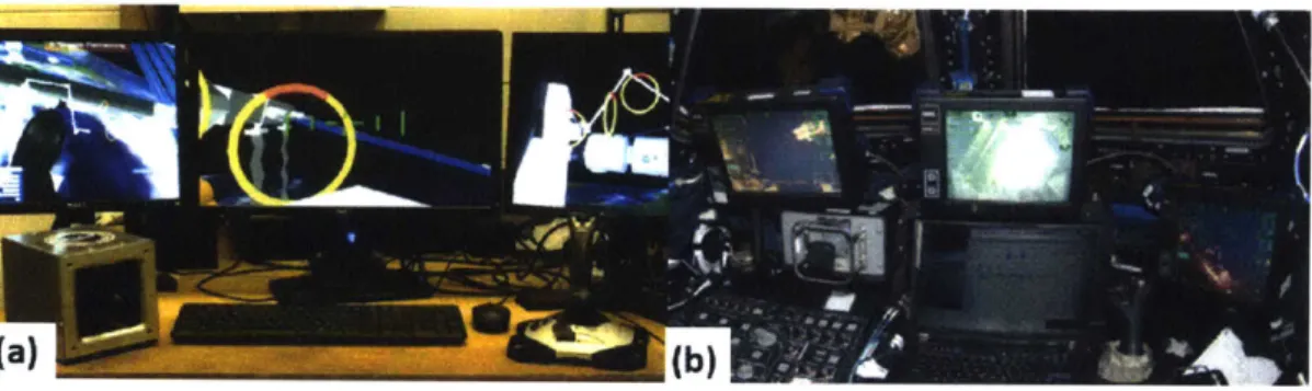
which has been used in several previous studies [27, 46, 72] with the traditional SSRMS dual-controller interface. The simulator environment was constructed using Vizard V virtual reality software (Santa Barbara, CA). The hardware included three monitors displaying different views of a modeled ISS, representing two fixed exterior camera feeds and a view from the end effector (Figure 1-la).
Figure 1-1: (a) The SSRMS simulator as traditionally configured. (b) SSRMS robotic workstation on the ISS.
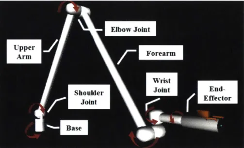
Like the actual Candarm2, the simulated robot arm is composed of three segments (Figure 1-2). However, in the virtual model of the SSRMS one of the shoulder joints remains locked, leaving six DOF. The virtual SSRMS is controlled at the end-effector, and nominally maneuvered using a two-Joystick interface similar to operation of the real Canadarm2 on station.
The nominal joystick interface consisted of a Left Hand Controller (LHC) used to control translation (Figure 1-3a) and a Right Hand Controller (RHC) used to control rotation (Figure 1-3b), mimicking the corresponding joysticks used on the ISS. Also like the ISS joysticks, grappling of a docking interface with the simulated SSRMS end-effector was activated by a trigger on the RHC. Some commands such as the brake toggle or switching between internal and external command frames were input through keyboard commands. The nominal joystick command configuration is shown
Table 1.1.
Figure 1-2: Segment and joint structure of the simulated Canadarm2. Red arrows indicate joint rotation directions.
(a) (b)
Figure 1-3: The simulator joystick interface Controller (b)
Table 1.1: Traditional joystck inputs for the SSRMS simulator.
Action Input Action Input
Forward eft Joystick Roll Right Right Joystick
Backward Roll Left
Up Pitch Up
Down Pitch Down
Right Yaw Right
Left Yaw Left
Brake "bk' Key Grapple Trigger
(Right Joystick)
Answer Message Foot Pedal
Rest Do Nothing Answer Message Thumb Button
DOF study only (Right Joystick)
limit DOF of the joystick interface. All input methods controlled the movement of the SSRMS end-effector, which could be maneuvered using an internal or external command reference frame. When operating in the internal command frame, axes of motion are relative to the SSRMS end-effector (Figure 1-4a), while in the external command frame axes of motion are relative to the ISS at the base of the SSRMS (Figure 1-4b). Within the simulator, the Canadarm2 could also be operated under two different velocity modes. The default setting, or "Coarse" mode was meant for large-scale movements covering long distances. For sensitive operations, such as controlling the end-effector within 2m of a surface or grappling an object, the SSRMS was operated in the "Vernier" mode, which maintains a slower maximum speed. In the simulator, this was set to one quarter the default maximum input velocity.
There are several errors, or violations, that a user might make while operating the SSRMS simulator, each of which would risk damage to the Candarm2, ISS, or astronauts if it occurred in the real world. Possible violations consisted of collisions of the arm, clearance violations, joint hard-stops, and singularities. Clearance violations referred to points where the arm was within a one meter distance of hitting the station
or other non-target object, while joint hard-stops and singularities are properties of the mechanical limits of the SSRMS - points where a joint has reached its limit of rotation or the arm cannot be moved in at least one axis direction. A display in a bottom corner of the center screen showing the SSRMS joint angles and their limits helps novice users avoid and maneuver out of joint hard-stops and singularities (Figure
1-5). FFrrwar UU Left Right Do n Down BBack (a) (b)
Figure 1-4: Internal (a) and external (b) command frames
Arm Joint Angles
- (2.4
Figure 1-5: Joint angle display for user reference in the SSRMS simulator, with angles indicated in degrees. Dark slider bars represent the current angles of each joint. A slider reaches maximum (all dark) when the upper limit of the joint is reached. A slider reaches zero when the corresponding angle is at zero degrees, the lower limit of motion.
I I . - - . _- . .
1.5
The JPL BioSleeve
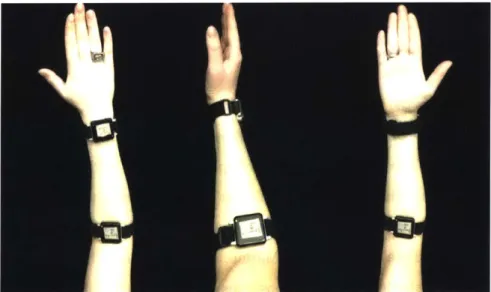
For this research, the JPL BioSleeve algorithms were adapted for use as a wearable gesture control interface to the simulator environment. The BioSleeve gesture recog-nition program was chosen because of proven reliability in its earlier single-input iterations for up to an hour, and was able to hold 17 individual static hand gestures (Figure 1-6) during that time
14].
"Static" hand gestures recognition referred tode-tection of specific, fixed poses as apposed to dynamic tracking of hand motion over time. During early assessments of gesture detectability, the 17 gestures shown in Figure 1-6 were made every ten minutes over the period of an hour at three different arm angles, and were recognized by the BioSleeve gesture classification software with
96.6% average accuracy
175].
When this test was repeated using a subset of 11 staticwrist and finger gestures, 99.8% average recognition accuracy was observed [751. Us-ing sEMG sensors arranged evenly around the user's forearm, static hand gestures are estimated from muscle activation patterns via a multi-class support vector machine
(SVM) classifier.
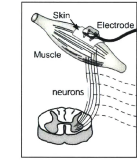
Figure 1-6: Set of 17 static hand gestures used in early JPL BioSleeve development When the nervous system signals the hand to move, it transmits electrical signals that activate muscles, causing them to contract, and resulting in hand motion. Surface electromyography sensors use a pair of electrodes placed in contact with the skin over a muscle of interest (Figure 1-7). During muscle activation, the action potential is seen
by each electrode as a voltage signal. The potential difference between the electrodes
is passed through an amplifier, and is recorded as a raw EMG signal 1111. Using an array of sEMG sensors, features extracted from the raw signals may be used to identify patterns of muscle activation beneath the skin [111. For research purposes,
this work used 14 Delsys Bagnoli sEMG sensors (Natic, MA) arranged in two bands of seven, evenly distributed around the forearm, for detection of muscle activation.
Skin
Electrode
Muscle
neuronsl
Figure 1-7: Surface electromyography sensors are placed upon the skin over muscles for detection of activation potential (Image credit: Delsys)
A prototype BioSleeve static gesture detection program was operated in Matlab
with a graphic user interface. With the BioSleeve's data processing (Figure 1-8), raw sEMG signals were processed in 300 ms windows and feature vectors extracted (in this case, signal standard deviations [761). Windows overlapped by 200is, such that new data is processed at a rate of 100 Hz. This means that when a new gesture was made, feature data representing the new hand position makes up one-third of the data at the following time-point. The 300 ms time-frame was chosen empirically as an interval long enough to allow clear, reliable signal data, while short enough to preventing a sense of lag between gesture and system response 176, 751. During calibration, a
user held each static hand gesture to be used as a robot command input for a fixed period (six to ten seconds) during which feature data was collected. These data were assigned to a series of class labels, and used to populate the SVM. After calibration, when the system was turned on, features extracted from active signals from the user's forearm were sent to the SVM, which used binary classification to determine which of it's labeled classes the current feature set most closely matched. Once classified, the system had to determine if the user's current gesture was actually the one identified,
SVM
--- Class
Support F Class - Prob.
uSckin Electrode Cairt xVectors i
lsiy Decision Poiie> .?
Commnand
Surface Electromyography
CalibrationU
.
Figure 1-8: Surface EMG signal proceessing and gesture recognition using the JPL BioSleeve
or was a false-positive caused by the user making a hand gesture outside of the
labeled classes that should not be acknowledged as a robot command. This was accomplished through a false-positive filter, which only allowed the classified input to be sent to the robot controller as a command if the probability of the current gesture
matching the gesture classified was greater than a specified value. This probability
was typically set to a default value of 0.5, but could be adjusted for person-to-person variation [761. If needed in the event of poor gesture recognition, the system allowed active control to be turned off, and further calibration data collected and added to "augment" the existing classes. This calibration augmentation increased reliability of gesture recognition over extended time periods (greater than a few minutes)
1761.
1.6
Thesis Structure
The first research problem listed in Section 1.1 is focused on the viability of a wear-able gesture interface for teleoperation in a complex environment. From previous literature on gesture interface implementations, we see that the existing paradigms of master-slave and single input each have limitations for the operations of a high DOF manipulator through a complex environment. Master-slave is inappropriate for a robot on the scale of the SSRMS, whose large work environment, kinematic differ-ences from a human arm, and limited operation speed would make scaling to human